
PROJECT 9
Camcorder Night Vision
CAMCORDERS ARE GENERALLY DESIGNED for well-lit scenes, using the light to create a quality color image for recording. To ensure that the image is seen by the camera in a similar way to our eyes, only the portion of the light spectrum that is visible to our eyes is processed. Infrared light falls just below red on the light spectrum, making up the wavelengths from about 750 to 1500 nanometers (nm). This light cannot be seen by human eyes, but it can easily be seen by the charge-coupled device (CCD) imaging system in the camera, allowing it to be used as a night vision viewer.
![]() LEDs: 8 to 24 infrared LEDs in a 5-mm through hole package; wavelength of LEDs is 800- to 940-nm infrared
LEDs: 8 to 24 infrared LEDs in a 5-mm through hole package; wavelength of LEDs is 800- to 940-nm infrared
![]() Camera: Low-lux black-and-white composite video camera
Camera: Low-lux black-and-white composite video camera
![]() Camcorder: Any camcorder with an external video input
Camcorder: Any camcorder with an external video input
![]() Battery: 6- to 12-V pack depending on number of LEDs
Battery: 6- to 12-V pack depending on number of LEDs
Unfortunately, you cannot simply add an infrared illuminator to your camcorder and use it to capture night vision video because the CCD imager contains a glass filter that blocks out most of the infrared light. The good news is that most camcorders allow a secondary video input to be recorded, and by feeding the output from a small black-and-white spy camera into this input, you can give your camcorder the ability to record night vision scenes that have been lit by some type of infrared illuminator. This project uses an inexpensive camcorder and a twenty-dollar black-and-white spy cam along with one of the light-emitting diode (LED) illuminators shown earlier to create a portable stealthy night vision camcorder.
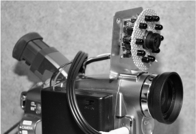
Figure 9-0 This camcorder uses a spy camera to see invisible infrared light.
Most video camcorders allow an external video source to be plugged in, essentially replacing the built-in CCD imager with some other compatible video source. This video input will often have some custom manufactured input jack with a label of “external,” “line input,” or “AV input.” You will need the cable that came with the camcorder in order to make this project, as each manufacturer will have its own special cable for that model of camera. On the older tape-based camcorders like the one shown in Figure 9-1, there was a 1/8 jack “standard,” that used a 4-ring 1/8-inch (in) male plug like the one shown in Figure 9-1, allowing any composite video source to be fed into the camera.
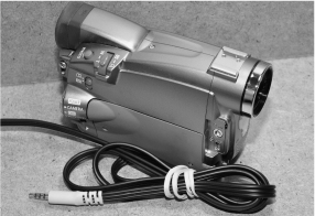
Figure 9-1 Any camcorder with an external video input will work for this project.
You will have to identify both the external video input and acquire the proper input cable in order to build this project, but if you kept all of the accessories from your camcorder, then that odd cable will probably be still sitting in the box, as it usually not used. Some manufacturers like to chisel the customer out of more money by making their own special connectors and then charging a ridiculous amount for the cable, so check your camcorder manual to make sure your camera supports video input and that you can acquire the necessary cables for a fair price.
Figure 9-2 shows the 1/8-in style connector that was popular on many tape-based camcorders. This connector is the same size as a typical 1/8-in headphone jack, but has four conductor rings, rather than the usual three as found on a headphone connector. At the other end of this cable is a set of standard RCA jacks to allow the camera to be plugged into any composite video-compatible equipment. This external video jack on most camcorders is called a “dubbing jack” as it can be used to record video from an external source or send video from your camera out to another video recorder. Check your camera’s manual to ensure it has this function.
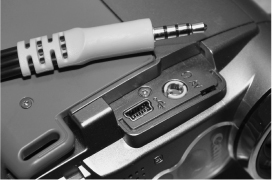
Figure 9-2 Our camcorder uses the 4-pin 1/8-in connector and is labeled AV.
We use many small video cameras for security work, machine vision experiments, and robotic projects. They range in size from half-an-inch square to quite large depending on the features, imaging system, and type of lens installed. For most indoor work, a small-board camera with a fixed medium to wide angle lens will be perfect, but there are times when you need to see a much larger area or over great distances, so these cameras have several body types that allow the use of multiple lens styles. Extremely tiny spy cameras will not have this option, as they use a very tiny glass or plastic lens built right into the housing. There will be a bit of a trade-off between image quality and size.
For most covert work, size will be the key factor in camera selection, so you probably won’t be dealing with multiple lenses or even have a choice. In Figure 9-3, you can see the huge difference in size between the long-range motorized lens telephoto camera on the left and the tiny spy camera at the front of the photo. The tiny spy camera has a simple fixed medium angle lens and will run from a 6-volt (V) power source for many hours. The larger camera uses a computer to control the motorized zoom lens and requires multiple power sources and electronic control systems in order to operate. For this project, an inexpensive black and white mini camera with a medium to wide angle lens that will run from a 6- or 9-V power source will be perfect.
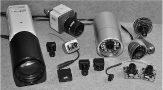
Figure 9-3 A variety of small security video cameras.
Security cameras and micro spy cameras will have a connection point for DC (direct current) power and a video output, and some will have an audio output or several control lines for onboard features such as gain, color, text overlay, and lens control. The most basic cameras you will probably work with most often will have only power and video connectors, or simply include three wires coming out of the tiny enclosure. The tiny board cameras with three wires will usually follow a simply color scheme of black or green = ground, red = positive power, and white, yellow, or brown = composite video output. Of course, it is always a good idea to check the manual for polarity and voltage before making any guesses.
The camera in the left of Figure 9-4 is quite advanced, having a built-in on-screen display system, many internal function parameters, lens control, and audio. This camera is somewhat large, so it has many buttons on the back side, audio and video jacks, DC-power jack, and a special connector to control a motorized lens. The basic low-lux micro camera on the right of Figure 9-4 only has a tiny connector with a three wire cable to allow power, ground, and video output connections. Since you will be powering the camera from a battery source, the smaller camera will be the better choice.

Figure 9-4 All video cameras will have connectors for power and video output.
When digging into the technical details of a security camera, one of the most important aspects will be the type of imaging device used, which will either be a CCD imager or complementary metal-oxide semiconductor (CMOS) imager. Both types of imagers convert light into voltage and process it into electronic signals. In a CCD sensor like the one shown in Figure 9-5, every pixel is transferred through a very limited number of output nodes (often just one) to be converted to voltage, buffered, and sent off-chip as an analog signal. All of the pixels can be devoted to light capture, and the image quality is high. In a CMOS sensor, each pixel has its own charge-to-voltage conversion, and the sensor often also includes amplifiers, noise-correction, and digitization circuits, so that the chip outputs digital bits. These other functions increase the design complexity and reduce the area available for light capture.
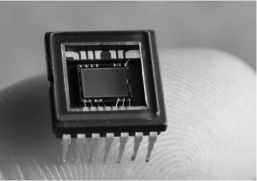
Figure 9-5 The CCD imager makes video by changing light into an analog voltage.
What this means is that for low-resolution and low-light imaging, CCD cameras are currently the best choice. CMOS imagers are used in very high-resolution imaging systems such as digital cameras and scanners as proper lighting is usually not a problem. If you have the choice between a hundred-dollar CCD security camera with a 0.5-lux rating and a fifty-dollar CMOS camera with a 1.5-lux rating, the CCD camera will offer a far superior image and work well in a low-light or night vision application. Resolution is not much concern in a security camera, as most are already beyond the actual capabilities of the National Television System Committee (NTSC) or Phase Alternate Line (PAL) composite video standard anyhow. The lux rating will probably be the most important specification on a security camera next to the type of lens and field of view.
Lux is the measure of light or luminous power per area. It is used in photography as a measure of the intensity, as perceived by the human eye. The lower the lux rating on a camera, the better it will see in the dark. For instance, a monochrome camera with a lux rating of only 0.5 lux will see much better in the dark than you could with your naked eye, and with the help of an infrared illuminator will be able to see into the darkness and display it on a monitor as if it were midday. Color cameras require much more light to achieve a decent image, and since they usually include infrared filters, they are not the best choice for night vision applications.
The focus can be set on these micro video lenses by loosening the tiny set screw as shown in Figure 9-6 in order to turn the lens clockwise or counterclockwise to gain the best focus for a certain installation. Most of these lenses will see perfectly from about 10 feet (ft) to infinity, but for closer focus, it will probably be necessary to make the initial adjustments. Although the optics on these tiny lenses range from good to poor, the image quality is always decent due to the low resolution of the composite video signal, along with the high quality of the CCD imaging device used. We found that a $30 color board camera will exceed the quality of a $1500 camcorder that was made five years earlier. Technology is always improving and becoming less expensive, so high-quality surveillance equipment is becoming more and more affordable for the “average” person.
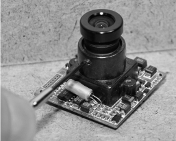
Figure 9-6 Smaller video cameras have a fixed focus that can be set.
This project uses the infrared radiation from an array of LEDs in order to see in complete darkness, and with the price of security gear at an all-time low, you can often purchase a complete night vision camera like the one shown in Figure 9-7 for well under $50. Inside the weatherproof aluminum shell, you will find a high-quality board camera, power supply, and another board with an array of infrared LEDs. By itself, this inexpensive security camera is a high-performing night vision camera with a range of about 50 ft, and has a very good color image for daylight operations. If you have not yet built an infrared illuminator or have a video camera for this project, consider purchasing a camera like the one shown in Figure 9-7, as it has all you need to complete this project.
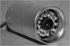
Figure 9-7 An outdoor security camera with built-in night vision LEDs.
Because the audio and video signals are prone to interference over longer distances, shielded coaxial cable is necessary in order to make the connection between the camera and the monitor or recording device. If your camera has RCA connectors at both ends, then you can use any standard patch cable to make the connection to your TV or monitor, but often you will need longer cables or have to install your own connectors. The standard coaxial cable type used for security cameras is the RG-59 type. This cable has a single insulated signal wire surrounded by a conductive shield. The “Siamese RG-59” version also includes a second shielded pair to allow camera power supplies to be located indoors at the location of the video recorder or monitor. For short connections of only a few feet, practically any coaxial wire will work just fine.
You may need to cut, strip, and solder your own connections, depending on your camera setup. Figure 9-8 shows the various stages of stripping down a coax cable to reveal the grounded outer shielding, as well as the protected inner signal wire. When connecting coaxial cable to an audio or video source, the inner wire carried the signal and the outer shield is connected to a common ground. When using coaxial cable to carry power, the positive supply is connected to the inner wire and the common ground becomes the outer shield. In almost all instances, the ground is common to all signals, including the power supply.

Figure 9-8 Coaxial cable is needed to carry the audio and video signals.
There are a few different types of connectors used on security cameras and composite video appliances, but the most common type is the RCA jack shown in Figure 9-9. This connector is the same one used on the back of a television set to connect older video players and camcorders. On the back of a TV or monitor, this jack will often be labeled “Video Input,” “Line Input,” “External Input,” and will use the same connector for audio and video. Most security cameras will output composite video in either NTSC or PAL format to be connected to any TV or monitor that can accept this input. Some of the smaller spy cameras may not have any connector, just bare wires, so it makes sense to adapt them to the RCA jack as shown in the upper part of Figure 9-9 if you plan to use them with standard TVs or monitors.
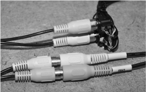
Figure 9-9 This is the most common type of composite video connector.
If your camcorder has a mount for an external light like the one shown in Figure 9-10, then you can use the slot to create a slide-in adapter for your external camera and infrared light source. The piece of aluminum shown in Figure 9-10 is the lid from a project box. It will be cut so that it fits into the light mounting slot on the camcorder, allowing the other components to be positioned over the top of the camcorder. If your camcorder does not include a light slot, then there are many other options available such as using a base that connects to the tripod screw hole or simply using Velcro on the side of the camera.
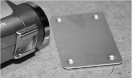
Figure 9-10 The external light mounting slot is going to hold the new camera.
Figure 9-11 shows the aluminum lid sitting up against the light mounting slot so that two points can be marked to begin cutting a slot into the aluminum. Practically any thin aluminum, steel, or plastic can be used to fit into the slot, but these project box lids are nice because there is plenty of room to mount the components and they can be cut using a notching tool or Dremel cutting wheel.
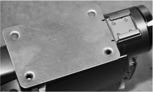
Figure 9-11 Marking the aluminum plate to cut the new slot.
The slot will be cut as shown in Figure 9-12 so that it fits snugly into the camcorder with very little play. The aluminum is thinner than necessary, so the corners will be slightly bent in order to create a tighter fit so that the camera does not bounce around or fall out of the slot.

Figure 9-12 The slot to be cut will fit into the light mount on the camcorder.
When working with thin aluminum or steel, a notching tool like the one shown in Figure 9-13 comes in very handy, as it can cut square bits out of the material. This tool can cut square holes and shapes out of material as thick as 1/16 in, and is great for cutting tabs or holes for liquid crystal display (LCD) panels, lights, or controls. A small hand file is also a must-have tool when working with thin metal or any type of project box that needs to have some type of machining done to it.
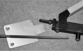
Figure 9-13 A notching tool and a hand file is used to carve out the slot.
Once the slot was cut with the notching tool and then cleaned up with the hand file, it fit perfectly into the light mounting slot as shown in Figure 9-14. Because the thin aluminum plate was thinner than the slot, it was bent at the front corners in order to offer a little more friction when fit into the slot.
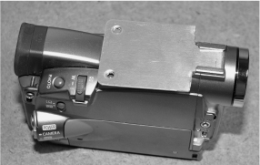
Figure 9-14 The tab is cut and fits snugly into the light mounting slot.
To offer an area to mount the camera and LED illuminator, the plate was bent at a 90 degree angle as shown in Figure 9-15 so that the face would point forward along with the camera lens. The external camera does not have to be perfectly in line with the original camera lens, but it does help to have both pointing in the same forward direction, especially if you plan to navigate a completely dark room by looking through the image on the camcorder viewfinder.
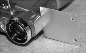
Figure 9-15 The aluminum part is bent into a 90 degree angle.
Our small video camera had a connector plug in the lower bottom corner, so we had to drill a hole into the mounting plate to install the connecting wires. Figure 9-16 shows the placement of the camera on the aluminum and the hole being marked for drilling.
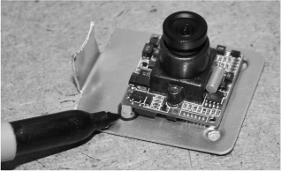
Figure 9-16 Marking the position of the camera connector to drill the hole.
Figure 9-17 shows the camera sitting on the aluminum mounting plate with the connector placed into the quarter-inch hole. Since this camera is so lightweight and small, it will only need a bit of double-sided tape to hold it onto the aluminum plate.
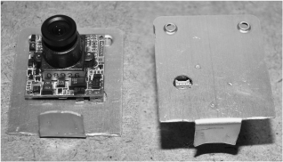
Figure 9-17 The connector hole drilled through the aluminum plate.
Rather than drilling holes for stand-offs and mounting screws, we just placed a bit of double-sided tape on the aluminum plate to hold the camera securely in place (Figure 9-18). The tape also creates an insulating barrier to keep the camera’s circuit board contacts from shorting out on the conductive aluminum surface.
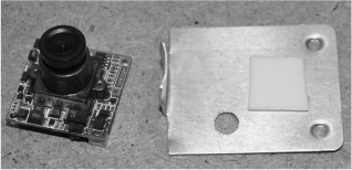
Figure 9-18 A small piece of double-sided tape will fasten the camera.
The camera and mounting bracket are shown sitting in the camcorder’s light mounting slot in Figure 9-19, ready to have the rest of the wiring and infrared light source connected. All that is left to do now is find a suitable battery pack that will power both the camera and the LED illuminator ring.
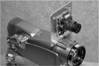
Figure 9-19 The camcorder now has two sets of electronic eyes.
The small connecting plug used on our board camera is shown in Figure 9-20, pushed through the hole drilled in the aluminum plate. These connectors are custom-made for the cameras, so care must be taken when pulling them out of the socket. Usually, the small security cameras have three connecting wires—ground, power, and video output.
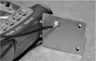
Figure 9-20 This small spy camera uses a tiny connecting plug on the back.
The infrared illumination ring light shown in Figure 9-21 is an earlier project made to fit over the lens of the small spy camera. The 10 LEDs are wired in series and powered by a battery pack to give each LED the proper voltage for optimal brightness. The 940-nm infrared radiation is completely invisible to human eyes, yet shows up on the low-lux black-and-white camera as typical white light. These LEDs are the exact same type that are used in remote controls to send bursts of infrared radiation to the receiver in your TV. Any of the night vision illuminator projects presented earlier would work as an invisible light source for this project, but the ring light already fit perfectly with this small spycam.

Figure 9-21 Infrared illumination will be provided by an LED ring light.
A 12 V battery pack with a built-in switch was chosen to power both the camera and the infrared LED array (Figure 9-22). Having 12 series-connected LEDs, each requiring 1.2 V, made this battery pack the perfect choice, and the camera also requires 12-V DC to operate. You could probably hack into the camcorder and pull the needed power right from the built in rechargeable battery, but this might be difficult as the lithium pack will probably have a lower voltage than necessary to operate an external camera. The camera and infrared illuminator will run for hours off of this small 1 amp (A) hour 12-V battery pack.
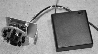
Figure 9-22 This 12-V battery pack will power the camera and the illuminator.
To get the camcorder to accept the external camera as the default video input, we had to jump into the onscreen menu system (Figure 9-23) and choose “AV Input,” which turned off the camera’s built-in color imaging system and replaced it with the signal coming from the black-and-white spy camera. Some cameras will automatically switch to the external input once a sync signal is detected, but you may have to play around in the menus to get your camera to switch to the external camera. Oddly, our camera only records the external source when in “playback mode,” which makes it act like a mini VCR.

Figure 9-23 Setting up the camera to use the external camera as an input.
Figure 9-24 shows how our completed night vision camcorder conversion project looked after fastening the battery pack and wiring to the camera body. All of the components can be easily removed if necessary. Switching between color daytime recording over to stealthy night vision mode only requires a few presses of the menu buttons.
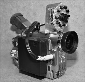
Figure 9-24 The completed night vision camcorder conversion project.
This rig also offers what was once referred to as “X-ray vision,” a controversial feature offered on some camcorders to remove the built-in infrared filter. We say controversial because it was found that in the daytime, certain clothing would appear opaque to the camera due to the ability of certain fabrics to pass infrared light. The company that offered this mode quickly removed it from their firmware, but many hackers figured out how to restore this functionality. Feel free to experiment with this “interesting” phenomenon, but be careful who you point your camera at!
The completed night vision camcorder is shown pointing at our parts closet (Figure 9-25 top left) as seen by the camera used to make these project photos. The top right image in Figure 9-25 is what the camcorder sees with the room lights off when using its own built-in color imaging system—not much at all. Switching over to the external low-lux black-and-white security camera (bottom left image), the camera does a little better in the dark since the spy cam has a much better ability to see in low-light conditions. With the infrared illuminator powered on (bottom right image), the scene looks well lit, yet we cannot see anything unless we view the scene through the camcorder’s viewfinder.

Figure 9-25 The converted night vision camcorder can see in complete darkness.
The nice thing about using this system as a night vision viewer is the ability to record what you are viewing, just as you could with the original imaging system on the camcorder. Navigating a room by looking through the image on the viewfinder is fairly easy to do as well, so this project is both a night vision viewer and stealthy security recoding system. For total stealth operation in complete darkness, place some black tape over the camcorders red indicator LED, but other than that, you can see in complete darkness with this unit, and your operations will be completely invisible to anyone in the room. Have fun on your covert spy missions!