
PROJECT 22
Repeating Camera Timer
THIS PROJECT WILL EXTEND the camera trigger hack project, allowing a timer to control both the focus and shutter release functions on a digital camera at an adjustable rate. This method of repeating time-delayed image taking is also referred to as “time-lapse photography,” and can be used to speed up time by piecing together hundreds of photos taken over the span of hours or even days. By first focusing the camera before the shot, the camera will be able to acquire moving targets with far fewer missed or blurry exposures. In this project, a timer feeds a 10-stage counter, allowing up to 10 individual control points, although only two are needed in order to control the camera relay interface.
![]() IC1: LM555 analog timer
IC1: LM555 analog timer
![]() IC2: 74HC4017B decade counter
IC2: 74HC4017B decade counter
![]() C1: 1 to 470 μF to control timer
C1: 1 to 470 μF to control timer
![]() Resistors: R1 = 1 K, R2 = 1 K, R3 = 1 K,R4 = 1 K, R5 = 1 K
Resistors: R1 = 1 K, R2 = 1 K, R3 = 1 K,R4 = 1 K, R5 = 1 K
![]() VR1: 50-K variable resistor
VR1: 50-K variable resistor
![]() Diodes: D1 = 1N40001 or similar
Diodes: D1 = 1N40001 or similar
![]() Transistors: 2N3904 or 2N2222A or similar NPN
Transistors: 2N3904 or 2N2222A or similar NPN
![]() Relays: Single-pole relay rated for 5 to 12 V
Relays: Single-pole relay rated for 5 to 12 V
![]() Battery: 3- to 6-V battery or pack
Battery: 3- to 6-V battery or pack
By using the other eight digital-output pins on the decade counter, several more cameras can be controlled, or more relays can be added to allow the controlling of various other electrical devices such as solenoids, alarms, lights, or even AC-operated appliances. The rate of photo taking can be controlled by a variable resistor, and by altering the value of the timer capacitor, rates of several photos per second, all the way down to single photos every hour, can be set. This project assumes that you have previously built the hacked camera trigger project, although you could certainly interface it to some other hardware as well.

Figure 22-0 This system will focus and shoot a photo at some repeating interval.
The small board shown in Figure 22-1 is a previous project called camera trigger hack, and it allows any electronic device to issue a focus-and-shoot command to the camera. We call this a hack because it requires removal of the original switch from the camera in order to hack into the two functions that control the focus and shoot signals on the cameras circuit board. You “may” be able to build this project without the previous project as long as your camera board will accept the 5-volt (V) digital signals from the 4017 decade counter into the camera’s board, but to be safe, this previous project adds a level of safety to ensure your camera will not be damaged by any external device or voltages.

Figure 22-1 This is the relay interface that controls the camera shutter switch.
Looking at the schematic shown in Figure 22-2, you can see that it also includes the two relays and driver transistors from a previous project called the camera trigger hack. The new components include the 555 timer-oscillator and the 4017 digital-decade counter, which will allow up to 10 digital devices to be actuated one after the other. The operation of this circuit is very simple as it is just a variable-rate pulse timer driving the clock input on the decade counter. To give the camera some time to focus before shooting, the focus relay is set off by count 0, and the shoot relay is set off by count 5. The counter always counts from 0 to 9 and then repeats, so this spacing offers the most time between functions.

Figure 22-2 This is the schematic for the repeating camera timer project.
Transistors Q1 and Q2 are relay drivers, which are actuated by the digital signal coming from the currently active pin on the 4017 decade counter. Potentiometer VR1 allows the pulse rate to be controlled to a large extent, but the capacitor C1 is responsible for setting the overall range of time, which could be as fast as several pulses per second to only a few pulses per hour. A value of 1 microfarad (μF) for C1 will allow VR1 to set the rate from several shots per second and a value of 1000 μF for C1 will slow down the pulse rate to 10 minutes or longer. You will have to experiment with larger capacitor values if you want to really slow down your frame rate. A value of 10 μF is probably a good start.
Resistor R5 and the LED are optional, as it is just a heartbeat that will show you the rate of pulses coming from the timer. It is nice to have the light-emitting diode (LED) installed during the testing phase as it gives some indication of the circuit operation. During our build, we also added LEDs to the control lines, so we had three LEDs in total.
The first capacitor we tested in the circuit shown breadboarded in Figure 22-3 was only 1 μF, so it gave a fairly quick pulse rate, allowing adjustment from about one photo per second to speeds that were too fast to control the camera. This rate was too fast to be of much use, but made it easy to take videos of the circuit in action. Our intention was to use this system to perform time-lapse photography, so we ended up installing a large 470-μF capacitor after we finished testing. You will have to experiment with various values for capacitor C1 to find the range you are looking for.
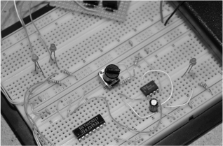
Figure 22-3 Breadboarding the circuit to test various capacitor values.
The small capacitor shown in the bottom left of Figure 22-4 is only 1 μF. This gave a frame rate of between 1 and 100 frames per second. The camera could only handle taking photos at a speed of about two per second, so for fast time-lapse photography or with a very fast camera, this might be a decent value to use. With the flash off, the camera was actually much more capable of taking photos quickly, but at several per second, the memory card would be filled in a hurry. The large capacitor on the lower right of Figure 22-4 is 1000 μF, and we ended up using that one to set the rate of photo taking to about 1 per hour. At this slow rate, the 4017 taps can be changed from 0 and 5 to 0 and 1 to keep the focus and photo functions closer together.
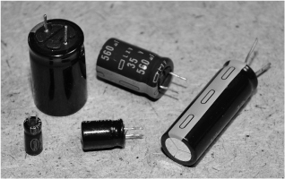
Figure 22-4 Various capacitor values we tried in order to control the frame rate.
Figure 22-5 shows the completed relay driver board jacked into the solderless breadboard where the timer and counter portion of the circuit are being tested. While you are prototyping this project, some interesting options might include using a beeper on one of the free counter pins to alert you before or after a photo has been taken, or possibly controlling more relays or multiple cameras. There is certainly a lot of room for expansion with only 2 of the 10 counter outputs in use.

Figure 22-5 The complete system is being tested with the timer on a breadboard.
The relay drive board is shown in Figure 22-6. This is a previous project called the camera trigger hack. The idea behind the relays is that no voltage is sent to the camera, only the closing of a circuit, which emulates exactly the function of the original shutter release switch that has been hacked out of the camera. Since most digital cameras have a two-position shutter release switch (focus and shoot), there are two relays used to copy this operation. You could get away with only one connection to the shoot function, but at the expense of having fast-moving targets possibly out of focus.

Figure 22-6 This is the relay driver board that safely controls the camera functions.
Once we had the timer working at a rate we were happy with, we added the six components on a small piece of perforated board and made the connections on the underside using some small wire. A circuit of this size hardly merits a real printed circuit board, and it only took a few minutes to move the parts from the solderless breadboard onto the perf board and then solder the wires to form traces (Figure 22-7). We decided to keep the relay board separate as it may end up being connected to some other activation circuit in a future project.

Figure 22-7 The timer circuit is built on another small perforated board.
The completed project ran fine from any voltage between 5 and 12 V, so we decided on a 6-V battery pack made up of AA batteries as the power supply. The completed rig, including the relay board is shown in Figure 22-8, connected to the hacked digital camera form a previous project. This system works very well for time-lapse photography or as a high-resolution security system.
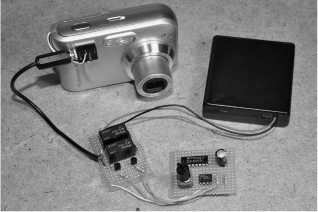
Figure 22-8 The completed repeating camera timer project with the relay board.
With the camera connected to an external power supply, and a large memory card, an entire day of high-resolution image capture can be done. Having the ability to take images at 8 megapixels means that details such as faces and license plates are highly visible, even when the subject is far away from the camera. Compared to a regular video security camera, this system has more than 10 times the clarity, but this is at the trade of frames per second. If high-detail long-term surveillance is your goal, then this rig will deliver.