
PROJECT 14
GPS Data Receiver
GPS is short for “Global Positioning System.” As the name implies, it is a globally available positioning and time system that uses a radio fix on multiple orbiting satellites. A GPS receiver will operate wherever there is an unobstructed view (line of sight) to four or more GPS satellites so that it can receive the radio signal from each satellite. The receiver uses the information it receives in the radio signal to determine the distance to each satellite. The position of the receiver is calculated by an algorithm that includes both the information and strength of the radio signal received from each satellite. With this information, exact time, and position data such as latitude, longitude, height from seal level, moving speed, and direction can be computed and displayed to the user.
![]() GPS1: Any GPS module with a digital serial output
GPS1: Any GPS module with a digital serial output
![]() Eval1: Optional sparkfun GPS evaluation board
Eval1: Optional sparkfun GPS evaluation board
![]() IC1: ATMEL ATMega32p or comparable microcontroller
IC1: ATMEL ATMega32p or comparable microcontroller
![]() XT1: 14.755-MHz crystal for microcontroller USART clock
XT1: 14.755-MHz crystal for microcontroller USART clock
![]() LCD 1: 16 character serial input text LCD
LCD 1: 16 character serial input text LCD
![]() LED 1: Red LED to display GPS status
LED 1: Red LED to display GPS status
![]() R1: 1-K current limiting for LED 1
R1: 1-K current limiting for LED 1
Having all of this location information available instantly from anywhere on the planet means that your next project can know exactly what time it is, where it is, how fast it is moving, and in what direction it is moving at any time. Robots can self-locate for autonomous operation and surveillance equipment can keep track of a person or vehicle location in a very precise manner. The good news is that you can add GPS capabilities to your project for under $100 and there are no licensing fees or user fees. The not so good news is that a consumer grade GPS is really only accurate to a radius of about 25 feet (ft), although for the most part the accuracy will be much better. If you own a handheld GPS unit, then you have already seen the limitations of these devices. Of course, even at 25 ft, the accuracy is more than enough to track a person or object along a city street and then display that data on a program such as Google Earth or Google Maps.

Figure 14-0 This project will connect a microcontroller to a GPS module.
A GPS module is a self-contained GPS receiver that does all of the difficult signal processing and computation for you. These inexpensive and amazing 1-inch (in) square boxes will lock onto all of the satellites in range and then start sending out the location and time data in a simple-to-read string that can be received by a microcontroller using a few input-output (IO) lines. This project will explore the basics of connecting one of these GPS modules to a microcontroller in order to receive the data and decode it into a usable format.
There are many different GPS modules available, and like all things, some are good and some are not so good. Being a fairly new technology, improvements are constantly being made, so you must do a little research to ensure that you find a GPS module that uses the most current technology. Some of the more important aspects to consider when choosing a GPS module will be: the output format, time to fix, antenna type, and available support. Support and documentation cannot be underestimated when dealing with these GPS modules. They will require some very precise communication to and from your microcontroller in order to operate properly. With good documentation and a support community, you should have no problem getting your GPS module working in a few hours, but don’t expect a happy ending if you find a budget receiver with little documentation, or you plan to be the first one to get that latest receiver working. We know—this is our second attempt at a GPS-based project, and our fist attempt was a frustrating failure because to having a module with almost no documentation and support!
The best source for GPS receivers and evaluation boards that we have found is the Internet-based electronics hobby supplier Sparkfun.com. They offer a wide range of reasonably priced GPS units along with full documentation and a forum where users can post questions and offer working source code for various models and microcontrollers. SparkFun also offers an evaluation board that takes care of the power supply, connector issues, and level translation between the serial port on the GPS and your microcontroller or computer. We found the evaluation board to be a great help when working with the GPS module as we knew any errors in communication would be in our own source code rather than in the actual hardware. The GPS module (SanJose FV-M8) and evaluation board (GPS-08334) we ordered from SparkFun are shown in Figure 14-1. The total cost of both items was under $140.

Figure 14-1 A GPS module and evaluation board supplied by SparkFun.
The FV-M8 GPS module made by SanJose Navigation is a powerful 32-channel GPS receiver with a 5-Hertz (Hz) output rate and a built-in antenna. This GPS module would be considered high end, but for under $100, it is a bargain for those who want to add fast response GPS navigation to a project. Having a built-in antenna also makes things much easier. This GPS was able to find a fix in less than a minute, even in a basement lab. The evaluation board from SparkFun allows several GPS modules to plug right in and take power from a USB port or external DC source. The evaluation board also includes a USB-to-serial converter and a level translator for serial communication with a PC. Using free software such as “Mini-GPS” made it extremely painless to get the module up and running to verify its operation.
GPS receiver modules have come a long way over the last few years. The tiny 1-in square FV-M8 receiver module from San Jose Navigation is ready to use as soon as power is supplied (see Figure 14-2). Once powered up, the GPS module will search for satellites and then send a 1-Hz “heartbeat” pulse down one of the input/output (IO) lines to show that it has a valid fix. The module will also send out serial data containing all of the relevant GPS information so that a microcontroller or terminal can decode the data. So, to add GPS capabilities to your project, you really only need three wires: one for power (3.3 volts [V]), one for ground, and one to receive the serial data! A few years ago, we tried to add GPS capabilities to a robot project using a much earlier GPS module, and failed after wasting a week trying to decode the data sheet. Nowadays, things are much easier.

Figure 14-2 The SanJose FV-M8 from SparkFun is a fully functional GPS in a tiny box.
Most GPS modules can also be configured via serial communications, but unless you need to change the default settings, the modules can be used without any prior setup or configuration. Serial communication speed, data transmit rate, and data format are some of the more common configurations that can be changed in most GPS receivers, but for this project we will simply work with the default settings as indicated in the datasheet for the GPS module.
The first step in connecting a GPS module is to supply the needed voltage and then connect the receiver and possibly the transmit line to your microcontroller. The data sheet will show you the pinout of the GPS connector, as well as all of the timing and communications parameters that are needed. If you are planning to use a development board that will accept the connector for your GPS module, then the IO pin configuration is not important at this time, but eventually you will probably want to reduce your project down to just the GPS module and a microcontroller. Figure 14-3 shows the section of the datasheet that indicates the purpose of all eight wires coming out of the GPS module. Out of the eight possible wires, we only needed three of them to get the data into the microcontroller: power (VIN), ground (GND), and transmit (TX1).
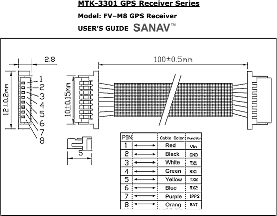
Figure 14-3 The datasheet will detail the IO lines as well as default settings.
A GPS module is fairly easy to connect to a microcontroller as long as you supply it with the proper DC power source and know exactly what type of data to expect from the transmit line. If the GPS module includes a “heartbeat” IO pin, then you can simply add a current-limiting resistor and an LED to create a visual indicator that will tell you when the GPS module has found a fix and is sending serial data. On our GPS module, the heartbeat IO line is labeled on the datasheet as “1PPS,” which means one pulse per second. On power up, this IO line will send out a constant voltage and then blink once per second as soon as the GPS has locked on to as many satellites as it needs in order to create a valid location fix.
To verify the operation of this GPS module, we ordered the evaluation board (Figure 14-4) from SparkFun, as it included a socket for the GPS and several other popular models. This socket will supply the required DC power to the GPS module and carry all of the other IO lines out to both a solder pad header as well as an RS232 level translator that will allow the data to be received by any computer with a serial port. For PCs without a serial port, a USB-to-RS232 converter is also included on the board so that data can be received on a virtual com port on the PC. Basically, with the evaluation board you cannot go wrong when it comes to connecting the GPS module up to a computer to read the serial data or send commands to the module. It’s all plug and play.

Figure 14-4 Initial testing will be done using the evaluation board.
Connecting the GPS module to the evaluation board and to a computer was just a matter of plugging in the cables. Since we had a 9-pin serial cable on our test bench for use with the Atmel STK500 programmer, we just moved it from the programmer’s socket to the SparkFun evaluation board. We then plugged the FV-M8 into the mating socket on the evaluation board and then added a 12-V DC jack that had the correct polarity as indicated in the evaluation board datasheet (Figure 14-5). For USB operation, the board will take power from the USB bus, so no external DC power source would be necessary.

Figure 14-5 Connecting the FV-M8 GPS module to the evaluation board.
As soon as the power switch was placed in the ON position, the status LED on the evaluation board lit up, showing that the GPS module had the proper DC power applied. Since we were using the 9-pin serial connector rather than the USB connector, we set the communication switch on the evaluation board from “USB” to “RS232.” The 9-pin serial port labeled “Port1” was then connected to the serial port on our PC using a standard “straight through” serial cable, not a “null modem” cable.
Once we had the evaluation board connected and powered up, the status LED went from solid to a 1 second pulse within about 60 seconds, indicating that the GPS now had a valid fix. Surprisingly, this was faster than our handheld Garmin GPS when both were powered up at the same time. The GPS module was able to gain a fix in under a minute even in a basement lab, so this was a good sign that it would be quite usable in a robot project or even a tracking device. The next step was to display the GPS data on the computer. This step was not as easy as we thought it would be.
We downloaded several free GPS data display programs from the SparkFun website as well as from the GPS module manufacturer’s website so we could view the data in real time. According to the FV-M8 data sheet and sales documentation, it would power up and begin to send serial data strings at 4800 BPS at a rate of 5 Hz (5 strings per second). Well, that seemed simple. The indicator LED was already pulsing at 1 Hz, indicating that the GPS already had a valid fix. For the next four hours, we attempted to receive this 4800 BPS data on all of the free GPS programs as well as with the built-in HyperTerminal program, but could not get any of the programs to receive the serial data. We tried several cables, and even went back to the USB port, but could not get any terminal program to receive the 4800 BPS serial stream. Since the datasheet clearly stated that the module would send 4800 BPS data on power up, and would not retain any serial configuration speed changes without a backup battery, we began to suspect that the evaluation board was nonfunctional.
The next day, we began to simply hack away on the project, trying random switch settings and other baud rates, and wouldn’t you know it—the data sheet was wrong! The FV-M8 GPS module defaults to 38400 BPS, not 4800 BPS as stated in the datasheet, so we were now up and running. Sadly, we cut the cables in frustration and was planning to wire up a new RS232 IC when we suspected the evaluation board was not working. It’s not often that datasheets have bogus information, but if you are using this same GPS module, be aware that it defaults to 38400,8,N,1 and not 4800,8,N,1 as stated in the datasheet.
Once the PC was set to 38400 BPS, the GPS data began to display on the screen as shown in Figure 14-6. The “Mini-GPS” program presents the satellite fix data in a configuration similar to many handheld GPS units, showing position and signal strength for all satellites it can receive from. You can also set the default parameters of the GPS module, changing the frequency and speed that serial data is sent. We tried changing the serial speed back to 4800 BPS, and this worked fine, but without a backup battery, the default speed went right back to 38400 BPS. We decided to use only the default settings that the GPS module had at power up, so that if power was lost, it would not be a huge task to get the module communicating with the microcontroller again. Sure, we could set the GPS for 4800 BPS, and program the microcontroller for the same speed, but then what would happen if the GPS lost power or if the backup battery failed? The microcontroller would be unable to reprogram or even communicate with the GPS module, and it would need to be removed and reprogrammed from a terminal set for 38400 BPS. Consider this issue when adding a GPS module permanently to some other project that has to communicate with it.
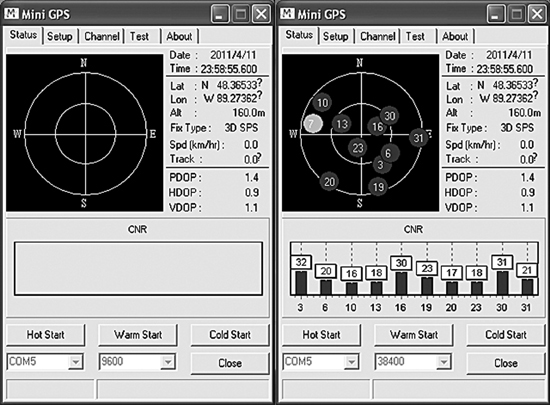
Figure 14-6 Receiving the GPS data on the “Mini-GPS” PC program.
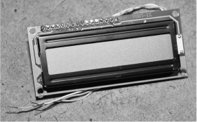
Figure 14-7 This is an easy to interface two-line serial LCD screen.
LCD screens are very easy to connect to just about any microcontroller. The small 16 character by two line LCD screen shown in Figure 14-7 needs only a single serial input in order to display characters. LCD screens that use serial, parallel, or I2C are easy to work with because many microcontrollers already support these languages, or have routines built into their compilers to add LCD support. We had this serial LCD in the parts box, and it was a perfect choice to display the data sent from the GPS module. Of course, the LCD screen cannot accept data directly from the GPS module, so a microcontroller must be used to first read the serial data from the GPS module and then send it out to the serial LCD module after formatting it into a compatible string.
Once you have verified that the GPS module is working properly and sending out serial data at a speed and format that you know, connecting it directly to a microcontroller is easy. Any microcontroller that can accept the transmitted serial data at the required baud rate can read the data from the GPS and then use it internally. Your project could be as simple as a Basic Stamp or Arduino reading only the TX line from the GPS module to acquire location data or more complex, controlling the functionality of the GPS module through its serial receive IO pin. In this experiment, we will simply read the serial stream as sent by the GPS module default configuration and then echo the time and location data back to the LCD screen.
Figure 14-8 shows the simple schematic that will accept GPS data into an Atmel 324P microcontroller and then send it back out to a serial LCD screen. We chose the ATMega324 because it had a dual hardware USART, and plenty of program memory for expanding the project into something more interesting like a robot navigation system. In the schematic, “CON-1” shows the solder pads on the SparkFun evaluation board and how they relate to the connector for the FV-M8 GPS module. Eventually, the GPS module will be connected directly to the microcontroller, but for prototyping, the evaluation board ensures that there will be no wiring errors while working on the microcontroller source code.

Figure 14-8 Using a microcontroller to receive GPS data and send it to an LCD screen.
Both the microcontroller and the GPS module will run from 3.3 V, so no level translation is necessary between the RX and TX serial lines. If the microcontroller were to be powered from 5 V, then some GPS modules may require level translation in order for serial communications to work between 5 and 3.3 V. Check your GPS module datasheet to ensure that it can be connected to your external project at whatever voltage your microcontroller is running from; 3.3 to 5 V Level translation is probably not necessary for receiving date from the GPS as the microcontroller, but going to the GPS, you have to be careful, as the higher voltage could damage the GPS module.
Since the serial LCD screen needed to communicate at 9600 BPS and the GPS module was communicating at 38400 BPS (its default setting), we needed to choose a microcontroller with a dual serial USART and then find a clock oscillator that would work for both baud rates. When working with lower-speed serial communications such as 2400 BPS or 4800 BPS, you can often get away with any clock speed, but for higher data rates such as 38400 BPS, there are “magic” frequencies that will ensure that you end up with an error-free communication system: 14.7456 was one of these well-known “magic” serial communication clock speeds, so it was easy to source this crystal. The canned crystal shown in the breadboard in Figure 14-9 was one of several that we had in the salvaged parts bin, and probably came from an older PC modem card.

Figure 14-9 An ATMega324p is chosen because it has a dual hardware USART.
If you are planning on communicating with your GPS at a lower baud rate, then you will not have to be so selective of your microcontrollers clock speed, but be aware that there will be a certain error level that may or may not cause a slowdown in your serial link from the GPS module. If you are constantly missing serial strings from the GPS module, then you may have to either adjust the serial transmit speed or choose a clock frequency that gets closer to the desired board rate with fewer timing errors.
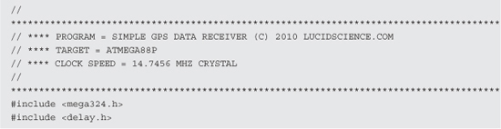
I wrote the basic GPS data receiver program in C for the ATMega324p microcontroller using AVR CodeVision, but it is very easy to follow and convert to just about any language. This program represents the minimal program needed to decode the GPGGA NMEA serial data string into its individual parts and then send them back out to the serial LCD screen. Most GPS modules output data in the NMEA (National Marine Electronics Association) format, which is a collection of standardized data formats that contain comma separated values following an identifier code. You will definitely have to get familiar with the data format sent by your GPS module and chose one of the many possible strings to decode. A Google search for “NMEA strings” or “NMEA sentence” will yield all of the information you will ever need for every possible NMEA string format.


By default, the FV-M8 GPS module sends several strings at a rate of 5 per second and one of these strings is the GPGGA string, which we found to be easy to understand. The serial data string for the GPGGA sentence will look like this:
![]()
Each of the numbers or characters following the “$GPGGA” identifiers represent the received and calculated GPS location data as:
![]()
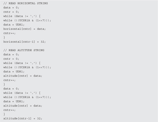
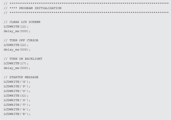
So, all your program needs to do is read the serial data stream and look for the “$GPGGA” identifier text and then parse the comma-separated data values until the end of the line. We wrote this GPS receiver test program in the most basic way possible so that it would be easy to follow the string decoding routine for translation into another language. There are no time outs or error checks being done by the string decoder routine; it just waits for the next “$GPGAA” identification and then reads the following comma-separated values into usable string variables. These values are then echoed to the serial LCD screen at one field per second so you can see the data sent from the GPS module. As shown in Figure 14-10, the program will start by sending the message “GPS LOADING...” and then wait for the next GPGGA data string to arrive for parsing.
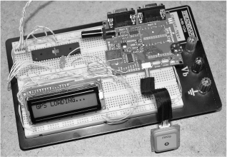
Figure 14-10 The microcontroller is now receiving serial data from the GPS module.
To verify the operation of the FV-M8 GPS module and compare its accuracy against a good quality handheld GPS unit, we let both GPS systems gain a fix and then displayed the data side by side as the program ran through its loop. Figure 14-11 shows the info screen on the Garmin handheld GPS, which is being used to verify the data strings received from the FV-M8 GPS module and echoed to the LCD screen. Both GPS systems managed to lock onto six satellites within 60 seconds, and the GPS module later found eight satellites from our indoor lab while the handheld stayed at only six. Both GPS systems show almost identical coordinates, but the handheld seemed to respond to movement a little quicker than the GPS module as we moved them both across the room. So far it was a close tie between the handheld commercially available GPS unit and the FV-M8 GPS module.

Figure 14-11 Comparing the GPS module data with the information on the handheld GPS.
After moving both across the room and back, the latitude values were very close, being 48-21.914-N on the Garmin handheld and 48-21.9223-N on the FV-M8 GPS module. When we plugged this data into Google Earth, it showed the center of our house, so it was certainly correct data. The difference between the 2 GPS modules was so small that we could not determine which one was more accurate using Google Earth or Google Maps (Figure 14-12). Actually, the GPS module had one decimal digit more accuracy than the handheld, but this is probably overkill considering the margin of error in GPS positioning. So far the GPS module was getting a great score, able to perform at least as good as or better than a good quality handheld GPS unit. The next test to be done will be the elimination of the evaluation board to get the GPS module talking directly to the microcontroller.

Figure 14-12 The GPS module and handheld GPS comparing latitude values.
We often do the prototyping on a breadboard. The connector on the GPS module was certainly too small for any breadboarding work. The female connectors shown in Figure 14-13 mate with the connector that came with the GPS module, and would be perfect for installation onto a circuit board. We decided to make a breadboard compatible connector so that we could further explore the functionality of the GPS module. Warning—ugly cable hacking to come!

Figure 14-13 the GPS module came with a small 8-pin connector.
The cable that came with the GPS had a male 8-pin connector at each end, so we decided that if we simply cut the cable in half, we could make two new cables—one with breadboard-compatible pins and another that could later be soldered to whatever circuit board we planned to make our GPS project on. The cable shown in Figure 14-14 was cut in half and then one side was separated so that each wire could be soldered to a breadboard compatible header pin. Since SparkFun also sold these small cables and sockets separately, we could always acquire another one ifwe decided to use the original socket on a printed circuit board later on.
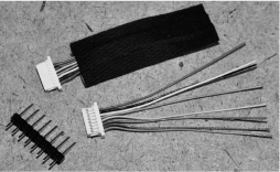
Figure 14-14 Converting the GPS cable to work on a breadboard.
Once the eight colored wires were soldered to the header pins, the GPS cable was now ready to be plugged into any solderless breadboard for rapid prototyping. The colors of each wire were fairly obvious, with red being VCC and black being GND, so it would be difficult to connect the power in reverse. Besides power and ground, the only other wire we planned to use, from the possible eight, was the serial transmit line (white wire). We connected all eight wires to the header pins just in case we wanted to experiment with changing the default parameters on the GPS module using the serial receive line. Figure 14-15 shows the completed breadboard compatible GPS module and cable.
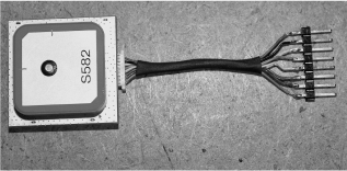
Figure 14-15 The completed breadboard compatible GPS cable.
With the evaluation board no longer included in the project, the size was greatly reduced as shown in Figure 14-16. We removed the LCD routines from the original source code and programmed a smaller ATMega88 microcontroller to receive the NMEA serial data strings from the GPS module. The heart beat LED was added from the “1PPS” line on the connector so that we could see that the GPS module was properly powered up and how long it took to get a valid location fix. This functionality is built into the GPS module, so only a current-limiting resistor was needed between the “1PPS” IO line, ground, and the LED. The GPS module serial transmit line “TX” was connected directly to the serial receive pin on the microcontroller so that the hardware USART could be used to receive the serial data at 38400 baud. Once again, the “magic” crystal frequency of 14.7456 was chosen so that serial communications would be error free.

Figure 14-16 Interfacing the GPS module directly to a microcontroller.
The program was modified so that when we pressed the pushbutton, the latitude value from the GPGGA string was memorized. Each time the memorized latitude value was found to match the current received value coming from the GPS module, an LED would be lit. We only took the first 7 digits of the Latitude data, so that the accuracy would be about 25 ft in any direction. A GPS is capable of higher accuracy, but only under ideal conditions such as being outdoors and stationary for some time. The goals of this test was to determine if the system could remember which room in the house we pressed the memorize button. After several tests around the house, it was determined that yes, this simple prototype could indeed remember which room we were in as long as we gave it a few seconds to gain a more accurate fix. While moving, the accuracy was limited to one end of the house or the other, but once stationary in a room, the accuracy seemed to be within 20 ft or so. Not bad at all!
This project proves that an inexpensive GPS module can certainly be used with a microcontroller to create a fairly accurate navigational system capable of determining time, latitude, longitude, direction, height, and location within about 20 ft from just about any place on the planet. Along with basic machine vision, and an obstacle-avoidance system a robot could be made to navigate the outdoor environment using the data received from the GPS module. A small and accurate stealth tracking system could also be made that would allow the user to later visually inspect the route on Google Maps or Google Earth. The possibilities are endless when your projects are given the ability to know exactly where they are on the planet at any given time, and as GPS technologies become more and more accurate, indoor robotic navigation will eventually be possible. Thanks for stopping by, we must now go back to our secret lab located at 296407.42 mE, 5350996.54 mN, 1080 ft.