
PROJECT 24
Motion-Activated Camera
THIS PROJECT USES a heat-sensing motion detector to trigger the shutter-release button on a hacked digital camera so that high-resolution images can be captured anytime a person or animal crosses in front of the motion-sensing zone. By hacking into an old motion-activated floodlight, the cost is kept to a minimum and based on a pre-existing system that is known to work well. This project converts the motion sensor for DC battery operation, allowing it to become portable and safe from high voltages.
This project also makes use of a circuit from a previous project called Camera Trigger Hack, which is a pair of relays and drivers fed into the shutter-release switch on a digital camera in order to mimic the original functionality of the switch. You could probably feed the output from this circuit directly into the camera shutter switch, but to be safe, the relay adds a level of isolation from the camera circuit board. Some cameras also have an external remote-control jack. This could also be used.

Figure 24-0 This rig will take a photo anytime it senses motion or heat changes.
Motion-sensing lights like the one shown in Figure 24-1 use a special heat sensor to detect movement of warm-bodied creatures. This sensor detects the body heat of the subject as it passes across a pair of small sensing elements inside the heat sensor. This heat sensor is also known as a Passive InfraRed (PIR) sensor and is the magic behind every one of those inexpensive outdoor security lights as well as most indoor motion-sensing units. Because these devices are mass manufactured, they are easy to find as surplus or even new for very low cost. Many security lights are tossed out when the plastic degrades or when the relay that controls the AC lights fails, so you can probably salvage the needed parts even from one that is deemed to be nonfunctional.

Figure 24-1 Any common outdoor motion-sensor light can be used for this project.
Most motion-sensing security lights will have an AC cover plate that includes one or more light sockets and a plastic sensor unit that can be removed from the base plate. Since you will not need any of the AC electric parts, tear down the sensor light until you have isolated only the motion-sensor box as shown in Figure 24-2. This part of the system is a standalone device that uses 120-volts (V) AC to switch an AC load through a mechanical relay. You could actually run this system from the AC line by isolating the relay contacts to switch your control electronics, but to play it safe, it is best to convert the motion sensor to run from low-voltage DC so you can power it from a battery pack.

Figure 24-2 Only the motion-sensor part of the security light is needed for this project.
If you are not interested in hacking up an AC appliance for battery operation, you could just purchase a ready-to-use motion-sensor board or kit from an electronics supplier. The two motion sensors shown in Figure 24-3 are from Sparkfun.com and are ready to run directly from 5-V DC. If you do plan to order a PIR sensor kit from an electronics supplier, ensure that you also receive the small Fresnel lens needed to spread out the sensing area over a larger area. The PIR sensor by itself is only capable of sensing movement a few inches away from the tiny window on the device, so the Fresnel lens is necessary. This lens will look like a small bubble or plastic sheet with tiny grooves on its surface.

Figure 24-3 Motion sensors are also available that run directly from DC current.
To open these motion-sensor boxes, you will need some brute force and ugly hacking since they are glued tight to keep out water and never intended for repair or modification. Of course, that will not stop the determined evil genius with a knife in hand! The easiest way to split open the plastic box is to run a sharp knife along the seal as shown in Figure 24-4, breaking the glue so that the parts can be pried apart. Once you have one side free, you can insert a thin screwdriver blade and split the two halves apart. Try to avoid damaging the half with the lens as you will be using it again later.

Figure 24-4 Sometimes the term hacking must be taken literally!
Once you have the front part of the motion-sensor casing open, you will be able to get at the circuit board inside. You can see the Fresnel lens in Figure 24-5, glued to the front half of the plastic casing. When you are done hacking the sensor, the goal will be to have the lens placed back in the same spot ahead of the sensor that it was originally in order to keep the field of view the same. Usually, you can glue the plastic cabinet back together or just fasten the front half over the circuit board or onto another project box that holds both parts together.
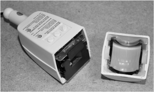
Figure 24-5 The two halves open up to reveal the circuit board inside.
There are usually one or more adjustments on the sensor to control time on, sensitivity, and delay, and these controls will be placed on the outside of the plastic so that they can be set. You may have to pop out the small plastic knobs as shown in Figure 24-6 to remove the circuit board from the casing as there will often be a connecting rod between the plastic knobs and the small timers soldered to the circuit board. Remember that these things are designed to be cheap, not to be easily taken apart so expect some parts to be glued in place or held with friction. You may have to do a little more hacking in order to free the circuit board.
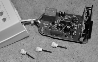
Figure 24-6 Removing the circuit board from the plastic housing.
The circuit board will often be made of two parts as shown in Figure 24-7—a main circuit board that contains some safety electronics and a relay to control the AC lights, and a smaller vertically mounted circuit board that will contain the PIR sensor and its control electronics. Most of the time, you can reduce the circuit down to only the small sensor board, as the AC board is not going to be needed in this project. Of course, this requires some reverse engineering of the circuit board, but being such a simple circuit, it does not take much effort at all.

Figure 24-7 This is a typical example of a motion-sensor circuit board.
Chances are you will not be able to track down a schematic for your security sensor, but most sensors work the same way and use similar components. The schematic shown in Figure 24-8 is a fairly common example of a motion-sensor schematic, using a few op-amps to control the amplification and sensitivity from the PIR sensor. The current trend is to use a single motion-sensor duty integrated circuit (IC) on the board, so if your electronics look a lot more simple than the board shown in Figure 24-7, it is probably one of the newer cost-reduced types. Either way, reverse engineering the system for DC operation is fairly easy.
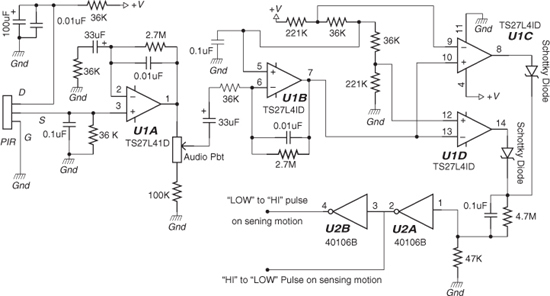
Figure 24-8 An example schematic from a common security-sensor system.
If your board has an easily identifiable IC such as the CD4011B NAND gate shown in Figure 24-9, then your reverse-engineering work is already half completed. Looking at the datasheet for the 4011B, it can be seen that like most logic DIP parts, the top left pin is VCC (positive) and the bottom right pin is GND (negative). So knowing that, you could feed the required DC voltage right into these pins and most likely have the entire board working from a battery pack. Of course, this is an ugly hack, and it is better to trace back to the regulation system to input your power there instead.
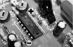
Figure 24-9 Identifying one of the board ICs to trace back the power and ground points.
A single-sided printed circuit board (PCB) is very easy to trace and reverse engineer because you have all of your traces on the bottom side and can see through the board by holding it in front of a bright light as shown in Figure 24-10. Seeing the components connected by the traces makes it very easy to follow the ground or power lines around the board in order to figure out how the circuit is powered. In this photo, you can see that there has already been a 3-pin part removed from the board—that was the voltage regulator that we found by following the lines back from the 4011B IC on the board.

Figure 24-10 Reverse engineering is easy on a board like this since you can see through it.
The security lighting system runs from a 120-V AC power line, but internally needs only 5 or 9 V to operate. The goal is to reverse-engineer the board so you can locate and bypass the onboard voltage regulator in order to power the sensor form a much safer DC-battery source. The voltage regulator will probably look like a common transistor, having three pins like the one shown that was removed from the board in Figure 24-11. Common values for the voltage regulators will be 7805, LM7805, LM78L05, 7809, LM7809, LM7808, and many other variations of the 78xx series of regulators.

Figure 24-11 This is the voltage regulator that powered the sensor board.
The 78L08 regulator we pulled from the board is a common 8-V positive voltage regulator that will change voltages from 12 to 20 V back to 8 V, which is the DC voltage that the electronic circuit was designed to run from. We actually found that our circuit ran fine on voltages as low as 5 V, and tested it as high as 9 V without any problems. To identify your voltage regulator, just look at the numbers printed on the components and enter them in your favorite Internet search engine to see if you can bring up a datasheet. If there is a silkscreen on the circuit board, then the regulator will be marked as IC1 whereas a transistor would be marked as Q1 or T1.
Once the voltage regulator has been identified, you can look at the data sheet in order to find the pinout diagram as shown in Figure 24-12. On the regulator, pin 1 was the output, pin 2 was ground, and pin 3 was the input—and this corresponded to what we found by following those traces to the various components and ICs on the board. Capacitors are marked on the negative side of the can, and so are diodes, so this can also help when trying to figure out which pins or traces are positive or negative.

Figure 24-12 The datasheet will show the pin diagram for the regulator.
If you can identify the voltage regulator as well as a datasheet to acquire the pinout information, then unsolder the regulator from the board, taking note of its orientation. You can install a pair of wires into the regulator’s place, adding one wire for positive and one for negative. Your new power supply will feed DC power directly to the board, so its positive wire will go into the hole where the output of the regulars was, and your new negative wire will live in the hole that is marked ground or common on the regulator pinout. Basically, you are removing the original regulator to replace it with a set of wires that will feed DC power right into the board.
The board we modified for direct DC power is shown in Figure 24-13, with the new DC power supply wires soldered into the holes that once held the onboard regulator. Now, the only other lines to trace are the ones that come from the relay. There are a few different ways you can take this project from here. It will depend on the design of your motion-sensor board and how you hacked into the digital camera trigger. If you hear the relay click when you power up your sensor board under your new DC power supply, then that is good news because you have enough voltage to engage the relay coil. If you do not hear a relay click, but the motion indicator LED seems to be working, then your relay may require more voltage or have been supplied from another current-limiting power supply on the board. In the later case, you will need to remove the relay and figure out which trace feeds the relay driver to activate the coil.

Figure 24-13 The hacked board now runs from 9-V DC rather than 120-V AC.
Our board had some odd AC supply powering the relay through an SCR, so we had to pull the relay and then trace back to figure out which point on the board fed the relay driver transistor or SCR. This job is easy to do once you know that the motion sensor is working because you can just probe the obvious pins with a voltmeter. When the test LED is on, the voltage will be somewhere between 1 and 5 volts as compared to zero volts when the test LED is off. This signal will likely come directly from the motion-sensor IC or the op-amp on the main board. Another sneaky trick is to just take this signal from the test LED, as it is always on when the relay should be on. It can be fed into your own relay driver board. We found a point on our board that went into the gate on the relay driver SCR and just soldered a wire right from there.
With the power running to the board, as well a line connected to the relay driver circuit, our hacked motion sensor was now self-contained and running from a 6-V battery pack. Figure 24-14 shows the hacked sensor board with an LED connected to the line from the relay driver. Each time we ran our hand over the PIS sensor, the LED in our small breadboard lights for some amount of time depending on the settings of the various adjustment resistors on the board. From here, the sensor board is ready to connect up to our hacked digital camera trigger board.

Figure 24-14 Testing the hacked sensor circuit board using an LED to signal motion.
If you enjoy the reverse-engineering aspect of this hobby, then you can further reduce your motion-sensor board by removing all of the AC regulation circuitry and the safety electronics. Since only DC is used now the safety circuit is pointless as well as the AC regulation components. On many of these sensors, the only board you need will be vertically mounted to the AC board, and it can be reduced to run on its own by doing a little creative reverse engineering.
Figure 24-15 shows a pair of sensor boards we hacked down to their minimal state by removing them from the AC board to run directly from DC power. If you take the reverse engineering this far, then you will also be losing the relay and driver, but the sensor system will still be fully functional. Instead of driving a relay, though, the sensor will output a 5-V signal whenever motion is detected. This will certainly work well with the hacked camera trigger relay board built in a previous project.
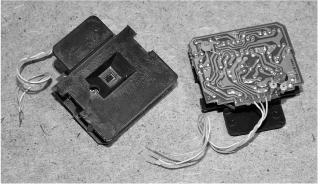
Figure 24-15 Reducing the sensor board to their absolute minimal configuration.
When you are done hacking and reverse engineering the motion-sensor board, it will be ready for your other projects, but will require the Fresnel lens to be attached again. If your sensor casing split so that the front half included the Fresnel lens like the one shown in Figure 24-16, then you can just use a little hot glue to fasten the circuit board in the same place it was before you hacked the system. The Fresnel lens expands the field of view, allowing the sensor to see an entire room or yard rather than just a few inches in front of its tiny glass window. Of course, feel free to test the sensor response with no lens as it may work perfectly in your own application, if short range is all that is needed.
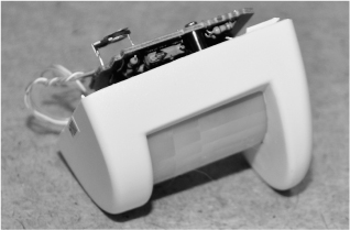
Figure 24-16 Attaching the Fresnel lens to the reverse-engineered sensor board.
The small relay driver board shown in Figure 24-17 will create a bridge between your newly hacked motion sensor and the hacked digital camera. This is a previous project called the Camera Trigger Hack. The idea behind the relays is that no voltage is sent to the camera, only the closing of a circuit, which emulates exactly the function of the original shutter release switch that has been hacked out of the camera. Since most digital cameras have a two-position shutter release switch (focus and shoot), there are two relays used to copy this operation. In this project however, both functions are tied together as the camera will need to respond quickly to the motion sensor. The downside to this is that the camera may not have time to spot focus on extremely fast-moving targets.
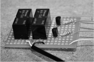
Figure 24-17 This is the relay driver board that safely controls the camera functions.
If you kept the original relay working on the motion-sensor board, then you do not need to use a separate relay board as you will already have the required isolation offered by the relay on the motion-sensor board. As long as you are only connecting to the contact points on the relay, then no voltages will be sent from your motion-sensor system, only an open or closed circuit, just like the original shutter release switch in the digital camera.
With all of the components working together perfectly from the 6-V battery pack, we found a suitable black box to create a self-contained unit that could be sent into the battle zone. The motion sensor was glued to the top of the enclosure as shown in Figure 24-18, with a hold drilled out so that the PIR window could see the outside world. The Fresnel lens part would then be glued over the box lid to expand the field of view. The battery and relay board were also mounted into the small plastic box so that the unit would be a fully functioning motion trigger system that could be plugged into the hacked digital camera or any other device we felt like operating under motion-detected control.
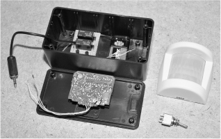
Figure 24-18 Creating a self-contained motion-sensing camera system.
The completed motion-activated camera is shown in Figure 24-19, waiting to capture in high detail the next person who dares to wander into our living room. As a security system, this project works very well, especially when a high level of detail is necessary. On a fresh charge, the camera can run for hours, snapping photos until the batteries are dead or until the memory card is full.

Figure 24-19 The motion-activated camera waiting for the next victim to set it off.
This system also works well in nature photography, where a stealthy setup is needed in order to capture some elusive creature or one that you don’t want to be anywhere near due to danger. We also found this project useful when we wanted several group photos that we were supposed to be included in and did not feel like fiddling around with the single self-timer on the camera. With this system, you just turn it on and the camera will keep on acting like your personal paparazzi as long as something is moving in its field of view!