CHAPTER 16
PerceptionBased Manipulation
CONTENTS
16.1 Extrinsic camera calibration
16.2 Integrated perception and manipulation
INTRODUCTION
Before developing mobile manipulation, we first consider combining perception and manipulation. Combining perception and manipulation also requires hand–eye calibration, and thus extrinsic camera calibration is discussed first.
16.1 Extrinsic camera calibration
Performing perception-based manipulation requires camera calibration. Intrinsic camera calibration was presented in Section 6.2. In addition, extrinsic camera calibration must be performed to establish the kinematic transform between a reference frame on the robot and the reference frame of the sensor. With good extrinsic calibration, one can perceive an object of interest, then transform the object’s coordinates from the sensor frame to the robot’s base frame. If this transformation is precise, a motion plan can be constructed and executed that enables the robot to successfully grasp the object.
Figure 16.1 illustrates a result of virtually perfect extrinsic camera calibration. This rviz view corresponds to data from a Kinect sensor mounted on the Baxter robot model. (This modified Baxter model will be described in the next section.) The modified Baxter model can be launched by first bringing up an empty world:

then launching:

The screenshot of Fig 16.1 is taken looking over the robot’s shoulder, from a perspective similar to that of the Kinect sensor. In the rviz display, point cloud points from the Kinect are colorized based on the z heights of the points. From this view, we can see many points on the surface of the model of the robot’s right arm and hand. These points correspond to the Kinect seeing the robot’s arm. The point-cloud points appear almost perfectly in agreement with the robot model, almost as if they were painted on the model. This agreement illustrates ideal hand–eye calibration. This level of precision is unrealistically good and is made possible only by self-consistency of the robot and Kinect models. In simulation, the Kinect sensor gets its points by ray tracing to surface points on the robot’s arm. These surface points follow from the robot model (in the URDF) and from knowledge of the robot’s state (joint angles). The transform of the Kinect with respect to the robot’s torso frame is precise, because this transform is part of the robot model. As a result, there are no calibration errors between the robot model the Kinect perception of that model.

Figure 16.1 Point cloud including Kinect’s partial view of robot’s right arm
In practice, the CAD model of a physical robot exhibits significant differences between model and reality. Further, precise knowledge of the poses of the robot’s links depends on the precision of the joint sensors, the quality of the robot’s home-angle calibration, and the precision of the robot’s kinematic model. In practice, the CAD models can be high quality, and the robot’s kinematic model and home-angle calibrations can be quite precise, and thus this contribution to hand–eye miscalibration may be small.
The largest source of error in hand–eye calibration typically would derive from uncertainty of the transform between the sensor (Kinect) frame and the robot’s torso (or base) frame. Finding this transform with sufficient precision is a necessity for successful perception-based manipulation. Finding this transform corresponds to extrinsic sensor calibration.
If the robot’s URDF model (including the kinematic model and the visualization properties described within the link’s CAD models) is sufficiently precise, visualization such as that in Fig 16.1 can be used to help identify the sensor transform experimentally.
A modified launch of the Baxter robot with a Kinect sensor can be started with:


The difference between the above launch file and the previous baxteronpedestalwkinect.launch launch file is removal of the line:

This line is inserted instead in a separate kinectxform.launch file, the contents of which are:
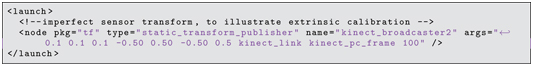
The numerical values in this transform are deliberately incorrect (offset by 0.1 m in x, y and z directions). This transform publisher is started with:

The control nodes and rviz can then be launched with:

The robot’s arm can be positioned conveniently within view of the Kinect by running (from the baxterplayfilenodes package directory):

Under these conditions, the Kinect’s point cloud appears as in Fig 16.2. Due to the imperfect Kinect frame transform, the point cloud no longer lies on the surface of the robot model’s arm. The point cloud is recognizably related to the shape of the robot arm and gripper, but it is offset from the robot model. The kinectxform.launch can be halted, edited, and re-launched (without needing to re-start any other nodes). By altering the transform values interactively, one can attempt to find values that result in point cloud alignment with the robot model, and this condition will indicate good hand–eye calibration.
(Note that the sensor frame in Gazebo simulation is called kinectpcframe, but when running the driver for a physical Kinect, this is called the cameralink, and thus different transform publications are needed for simulation versus physical equipment.)
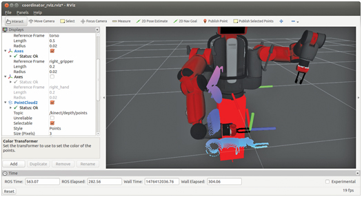
Figure 16.2 Offset perception of arm due to Kinect transform inaccuracy
As an alternative, a vision target may be attached to the arm with a known attachment transform, and the arm can be commanded to move the target to different poses in space. By associating Kinect snapshots with corresponding forward kinematics solutions, one can compute a best-fit explanation of the data in terms of a camera transform with respect to the robot’s base frame.
Assuming extrinsic sensor calibration has been achieved to adequate precision, one can use sensory information to plan and execute manipulation. An example of this using the Baxter simulator is introduced next.
16.2 Integrated perception and manipulation
In Section 8.5, an object-finder action server was described. Coordinates of an object of interest can be inferred from point-cloud images. In Section 15.4, an object-grabber action server was presented, with which an action client can specify manipulation goals, including an object ID and its pose. Putting these two capabilities together, a robot can be capable of perceiving objects of interest and manipulating them.
To combine these capabilities, a Kinect sensor is retrofit to the Baxter robot (model and/or physical robot). A model file that achieves this is baxteronpedestal.xacro in the package baxtervariations. This model file, below, merely combines individual model files.
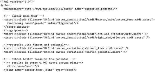

In the above, three files (the base and two grippers) are included from the package baxterdescription, which is a model of the Baxter robot provided by Rethink Robotics. Two additional included files are from the package baxtervariations (within the accompanying repository) that are a simple pedestal (a rectangular prism) and a Kinect model. The file kinectlink.urdf.xacro is essentially identical to simplekinectmodel2.xacro used in the object finder of Section 8.5, except this model is not attached to the world. (It is only attached to a link called baselink.) The baxterpedestal.xacro model constitutes the baselink. The two joints declared in baxteronpedestal.xacro rigidly attach the Baxter base to the pedestal and the pedestal to the world. This combination of models integrates the Kinect sensor (which is used in the object-finder package) with the robot and grippers (which are used in the object-grabber package).
This model can be launched by first bringing up an empty world:

then launching:


Figure 16.3 Result of launching baxter_on_pedestal_w_kinect.launch
This will bring up the Baxter model, mounted on a pedestal and augmented with a Kinect sensor and located in front of a table holding a block, as shown in Fig 16.3. (Note: if the block has fallen off the table, reset its position via the Gazebo GUI, under edit, choose “Reset Model Poses.”)
Once the Baxter simulator is ready, control nodes can be launched with:

This launch file starts 18 nodes, including six action server nodes, four service server nodes, a marker-display listener node, two static-transform publishers, rviz, and four simple nodes that run to a quick conclusion. Most of these nodes were introduced earlier.
The four nodes that run to conclusion perform actions to enable Baxter’s motors, set the gripper ID on the parameter server, command the head-pan to zero angle (in case it starts up rotated, occluding Kinect vision), and run a playfile to move the arms to an initial pose (with via points that avoid hitting the cafe table).
The two static-transform publisher nodes are brought in by including a launch file from the cartesianplanner package. These publishers establish frames genericgripperframe and systemrefframe.
An rviz display is started with reference to a pre-defined configuration file. The triaddisplay node from the examplervizmarker package is started up, which assists in displaying object-finder results within rviz.
The four services started include the Baxter playfile service (which is not necessary, but potentially useful); the object-manipulation query service introduced in Section 15.2; the generic gripper service that controls Baxter’s right gripper, as introduced in Section 15.3; and a setblockstate service, from the examplegazebosetstate package. This latter service is not necessary, but it can be useful for running manipulation tests. Each time this service is called, it re-sets the toy-block model to a random pose, constrained to lie on the table and within reach of the robot.
With assistance from the above nodes and services, the primary work of the vision and manipulation system is performed by six action servers. Four servers support object manipulation, as illustrated in Fig 15.1 in Section 15.1. These include trajectory streamers for both the left and right arms (as described in Section 14.5), a Cartesian move action server (as described in Section 14.9) and an object-grabber action server (Section 15.4). The object-grabber action server awaits goals to perform manipulations.
To combine perception and manipulation, an object-finder action server (from Section 8.5) is also launched. The server awaits goals to find object poses.
The sixth action server, introduced here, is a commandbundler from the coordinator package.
With these nodes launched, the Baxter robot will be in the pose shown in Fig 16.4.
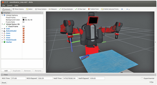
Figure 16.4 Result of launching coord_vision_manip.launch
In this pose, the arms are pre-positioned to prepare to descend on objects from above, without hitting the table. Further, the arms are positioned to avoid occluding the view of the Kinect sensor. The Kinect point cloud is displayed in rviz, from which a block on the table is apparent.
To invoke object perception and manipulation, a client of the coordinator can be started with:

This client asks the coordinator to: find the table surface, perceive a block, plan and execute grasp of the block, and move the arms (with grasped block) to the pre-pose position. Figure 16.5 shows the result of a request to locate a toy block on the table. The object finder computes the location of the block from point-cloud data, and it uses the triaddisplay node to place a marker in rviz to illustrate the result of this computation. An example result of this step is shown in Fig 16.5. This behavior is consistent with the object finder described in Section 8.5. The only difference is that the Kinect is mounted to the Baxter robot, and the frame of the Kinect sensor is knowable with respect to Baxter’s torso frame (since they are both connected to a defined baselink associated with the pedestal).

Figure 16.5 Result of coordinator action service invoking perception of block
Given the object frame, the next objective is to grab the object. This action is invoked similar to the example exampleobjectgrabberactionclient described in Section 15.5. Code from this example was incorporated in the commandbundler action server to invoke the GRASP goal for the object-grabber action server. The robot’s arm moves to approach from above (based on the perceived object coordinates and recommendation from the object-manipulation query service), opens the gripper fingers (using the generic gripper service interface), descends to the grasp pose, closes the gripper, and departs from the table with the part grasped.
Figure 16.6 shows an intermediate state of this process, in which the gripper is positioned at the grasp pose. The axes displayed in rviz show that the gripper and object frames have the desired grasp transform relationship.

Figure 16.6 Result of coordinator action service invoking move to grasp pose
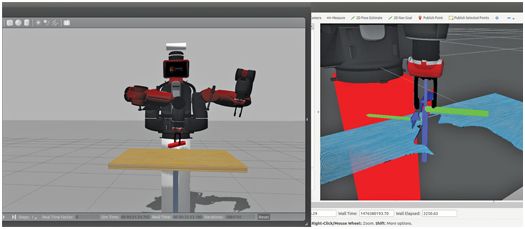
Figure 16.7 Result of coordinator action service invoking move to depart pose
Once the object is grasped, the robot performs a depart move, corresponding to lifting the object in the z direction. The result of this move is shown in Fig 16.7. A Cartesian move is appropriate for this step so that the robot does not bump the object against the table and lose grasp.
After a Cartesian-move departure from the table, the robot performs a joint-space move to a defined pre-pose (still grasping the block).
A second action client can be invoked to drop off the block, with:

This client specifies a hard-coded drop-off pose for the object. This move relies on the object-grabber action server to invoke a joint-space motion to the approach pose, Cartesian descent to the drop-off pose, opening of the gripper, and Cartesian withdrawal from the drop-off pose.
Figure 16.8 shows the robot at the drop-off pose, just before release.
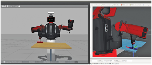
Figure 16.8 Result of coordinator action server invoking object drop-off
After opening the gripper and performing a Cartesian-move departure in the vertical direction, the robot is commanded to return to its pre-pose position.
Clients of the command bundler action server receive results back from the action server. If any errors are reported, the client has the opportunity to examine these codes and attempt error recovery.
A third client node, coordinatoractionclienttester, combines object pick-up and drop-off in a loop. This action client can be run with:

This client node runs a continuous loop sending goals to the coordinator and logging results. It repeatedly asks the coordinator to perceive a block, plan and execute grasp of the block, and place the block at specified coordinates. After each result from a goal request, the client evaluates the result, logs data regarding failures, then invokes the setblockstate service to reposition the block (at a randomized, but reachable pose) on the table to prepare for another iteration.
Having introduced the components of integrated perception and manipulation, we now examine some of the details within the code.
The launch file coordvisionmanip.launch in the coordinator package consolidates a variety of behaviors useful for perception and manipulation. The node commandbundler.cpp has action clients of both an object-grabber action server, as described in Section 15.4, and an object-finder action server, as described in Section 8.5. The command bundler node provides an action server, maniptaskactionservice, that communicates with action clients via the ManipTask.action message. This action message defines goal components as follows:
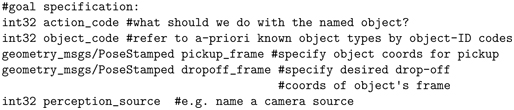
The actioncode field selects one of the capabilities of the action server within node commandbundler.cpp. The action codes, defined within the goal field of the ManipTask.action message, include: FINDTABLESURFACE, GETPICKUPPOSE, GRABOBJECT, DROPOFFOBJECT, and MOVETOPREPOSE. The simplest of these action codes is MOVETOPREPOSE, which merely commands the robot to raise its arms to a pose that does not interfere with the Kinect sensor’s view.
The action code FINDTABLESURFACE invokes functionality of the object-finder action server that identifies the height of a horizontal surface. Identifying this surface makes it simpler to find objects sitting on the surface.
Most actions are performed with respect to a specific object. An object is referred to by a unique identifier code in the objectcode field of the goal message. These codes are defined in the objectmanipulationproperties/objectIDcodes.h header file.
The action code GETPICKUPPOSE requires additional specifications. The object to be grasped must be specified via an object ID in the objectcode field. Further, the field perceptionsource must be set to a perception source ID (which is currently defined only as PCLVISION). If PCLVISION is specified, the object finder is invoked to find the specified object on the table surface. In this case, if the object finder successfully locates the specified object, the object pose is returned in the result message in the field objectpose.
The action code GRABOBJECT invokes motion planning and execution that includes a joint-space move to an object-approach pose, a Cartesian motion with open gripper to straddle the object with the gripper fingers, grasp of the object, and Cartesian departure from the grasp pose. The GRABOBJECT action requires specification of the object ID, which is necessary for the motion planner to infer the desired gripper pose based on the object pose and a desired grasp transform.
These actions are illustrated in the client node acquireblockclient.cpp in the coordinator package. This node starts by sending the arms to a hard-coded pre-pose, which has the arms out of the way of the Kinect’s view, and has the grippers positioned to prepare for manipulation. The following lines invoke this behavior:
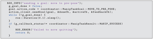
The action code MOVETOPREPOSE requires no other goal fields to be populated. After sending the goal, the main program inspects the global variable ggoaldone, which will be set by the action client’s callback function when the action server returns a result message. The action client’s callback function will receive a result message from the action server. The result field manipreturncode should return MANIPSUCCESS if the goal was successfully accomplished. This value is inspected, and the client program quits if the goal was not successful.
Next, the acquireblockclient node invokes the find-table behavior with the lines:
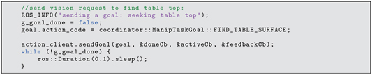
For finding the table top, only the action code is required in the goal message. As with the MOVETOPREPOSE goal, after the goal is sent, the main program inspects ggoaldone, which will be set by the action client’s callback function when the action server returns a result message.
Next, the action client sends a goal to find the pose of a toy block object on the table surface, using the following lines:
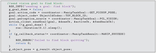
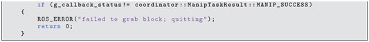
In this case, use of point-cloud processing of the Kinect data (perception-source PCLVISION) is specified within the goal message. If finding the object is successful, the result message returned to the action client callback function will contain the object’s pose. In the current example, failure to find the object causes the action client node to quit. More generally, a recovery behavior could be invoked, e.g. to look elsewhere for the object.
Assuming the object was found, the robot is next commanded to grasp the object, using the following lines:
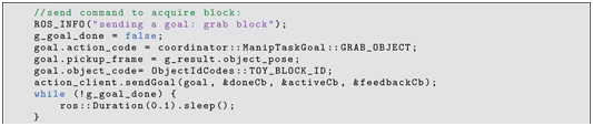
In the above, the goal action code is set to GRABOBJECT, the object ID is set and its pose is specified (per the result returned by the prior vision call). As in the previous instances, the main program examines the ggoaldone flag to determine when the action server has finished. If the return code does not indicate success, the program quits. Alternatively, error recovery could be attempted (e.g. to look for the part again and re-attempt grasp).
If the object is successfully grasped, the MOVETOPREPOSE behavior is again invoked, and this action client then concludes.
A second illustrative action client is dropoffblockclient.cpp. This node hard-codes a drop-off pose, then uses it within the DROPOFFOBJECT behavior with the following lines:
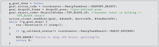
In the above, the goal field dropoffframe is set, as well as the object ID. The drop-off frame refers to the desired pose of the grasped object, and thus the object ID is required to deduce the corresponding tool-flange pose from the associated grasp transform. As before, the ggoaldone flag is polled, then the result code is inspected to evaluate whether the drop-off was successful.
The node coordinatoractionclienttester illustrates combining object acquisition and object drop-off. The goal dropoffframe is set with hard-coded values. Perception, grasp and drop-off are called repeatedly, using lines of code identical to those in the pick-up and drop-off action client examples. After each attempt, the block pose is randomized, and the perception, grasp and placement actions are repeated.
16.3 Wrap-Up
In this chapter, perception and manipulation were combined to enable vision-based manipulation. The previously introduced object-finder action server and object-grabber action server were used together, coordinated by a command bundler. For vision-based manipulation to work, it is important that the imaging source is calibrated to the robot. It was shown that rviz can be used to visualize the quality of extrinsic camera calibration, and it can be used to perform calibration interactively.
The example command bundler action server and the corresponding action client nodes presented here illustrate how to integrate perception and manipulation. Even greater flexibility can be realized if the manipulator is mobile, as discussed next.