CHAPTER 17
Mobile Manipulation
CONTENTS
INTRODUCTION
Mobile manipulation can be illustrated by combining the Baxter model with our previous mobot mobile platform. The mobile manipulator can then take advantage of all of the developments presented in sections III (perception), IV (mobility) and V (manipulation).
17.1 Mobile manipulator model
The mobile-manipulator model is contained in the file baxteronmobot.xacro in the package baxtervariations. The contents of this model file are:

This model brings together a mobile base model (mobotbase.xacro), the Baxter model, left and right end effectors, and a Kinect model. The Baxter model is a modified version of the original with the pedestal removed (as well as multiple sensors disabled). The mobile base is nearly identical to the mobot-with-Lidar model in package moboturdf (described in Section II). However, the height of the mobot is elevated approximately to the same height as Baxter’s pedestal.
The Baxter model base frame is attached to the mobottop frame of the mobile base using a fixed baxterbasejoint, defined in the baxteronmobot.xacro model file.
A Kinect sensor is added to the robot model by including the Kinect model file kinectlink.urdf.xacro from package baxtervariations. This model file is the same file that was included in baxteronpedestal.xacro (also in the baxtervariations) in Section 16.2. The Kinect model file contains a joint that attaches the Kinect link to Baxter’s torso frame.
The combined mobile base and Baxter robot appear as in Fig 171.

Figure 17.1 Gazebo view of a mobile manipulator model
This model includes the functionalities of the Baxter robot, the Kinect sensor and a mobile base with a LIDAR sensor. The associated sensors and controls support map making, localization, and navigation, as well as 3-D point cloud perception and robotic manipulation.
17.2 Mobile manipulation
Mobile manipulation is illustrated using the following procedure. First, launch Gazebo and the baxteronmobot model with:

(Note: mobot uses a LIDAR Gazebo plug-in, which requires a GPU or suitable emulation.) Next, start the manipulator controls. Wait for simulator to stabilize. Then, launch a variety of nodes and services, including the command bundler with:

This launch file is nearly identical to that used in Section 16.2, except that it includes nodes for mobility. The file baxtervariations/mobotstartupnavstack.launch is included. This launch file starts the AMCL localizer, loads the costmap and movebase parameters, and starts the movebase node. Two utility services are also started: openloopnavservice and openloopyawservice, which enable simple open-loop control over the base (e.g. for backing up a defined distance).
The mobile-manipulation process can be commanded in increments by running a sequence of nodes. Commanding:

invokes object perception and grasp, as in Section 16.2. Once the block has been grasped, the mobile base can be commanded to move backwards 1 m with the manual command:

then it can be commanded to rotate counter-clockwise 1 radian with the service call:

These commands are used here to simplify the planning process within movebase. When the robot is close to the table, the movebase planner may consider the robot to be in a fatal pose from which the planner cannot recover. Further, the planner has some difficulty invoking reverse motion, which is essential for the robot to depart from its close approach to the table. By inserting manual motion commands to clear the robot from the table and point toward the exit, subsequent automated planning is simpler and more robust.
At this point, automated planning and driving can be initiated with:

This client requests that the mobile base move from its current pose to a goal pose near and facing a second table located outside the pen.
Once the robot has approached the second table, an open-loop command to approach the table closer can be invoked with:

This command assumes that the movebase process successfully achieved a pose facing the second table, offset by approximately 0.7 m (to avoid perception of entering a fatal region). (This open-loop presumption will be relaxed later.)
With the robot having approached the second table, a block drop-off command can be invoked, using a hard-coded destination with respect to the robot’s torso:

The above incremental process illustrates the steps involved in mobile manipulation. A weakness, however, is that the pose of the robot with respect to the second table may be insufficiently precise for successful block drop-off. More robustly, one would invoke perception to fine-tune the approach pose and to perceive a drop-off location. Such improvements are illustrated in the node fetchandstackclient, which combines all of the above steps in addition to perception-based approach and drop-off. This node can be run with:

The fetch-and-stack node includes action clients of both the command bundler (for perception and manipulation) and movebase (for navigation planning and execution). It also has clients of the open-loop base translation and yaw services. This node incorporates the separate commands introduced above, including block perception and grasp, open-loop base back-up and re-orientation, and invocation of navigation. In this node, the navigator is assisted by first commanding motion to a via point near the starting pen exit, then commanding approach to the second table. Once the movebase approach to the second table has concluded, the fetch-and-stack node consults tf to find the robot’s base relative to the map frame (as computed by AMCL). From this pose, offset from the known map coordinates of the second table is computed, and the open-loop approach service is invoked for close approach to the table.
The initial and final operations of fetch-and-stack are illustrated in Figs 17.2 and 17.3. Figure 17.2 shows the mobile robot in both Gazebo and rviz views, positioned initially in front of a table with a block. The rviz view shows the robot’s pose within a global cost map. The scatter of uncertainty of robot pose is initially fairly large, since the robot has not yet moved, and thus there is no corroborating evidence of its pose beyond the LIDAR view of its start-up pose. Nonetheless, grasp of the object can be accurate, since its pose is based on the robot’s perception from Kinect data.

Figure 17.2 rviz and Gazebo views of mobile manipulator immediately after launch
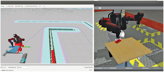
Figure 17.3 rviz and Gazebo views of mobile manipulator stacking fetched block
Figure 17.3 shows the conclusion of the fetch-and-stack client, after the robot has followed its navigation plan, approached the second table, found the block on the second table, and stacked the grasped block on top. The rviz view in Fig 17.3 shows the computed path (thin blue line) and LIDAR pings (red spheres) aligned with the wall to the robot’s left, which allows localization.
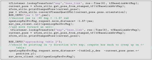
Lines 275 through 291 of fetchandstackclient.cpp, shown below, perform final approach to the second table. Desired coordinates of approach are known, and the tfListener is consulted to find the pose of the robot at the end of the movebase command (which is deliberately short of the final destination). The open-loop yaw service is invoked to correct for any orientation misalignment, and the open-loop translation service is used to advance the robot to a computed distance from the table.
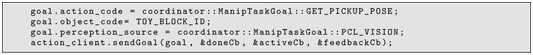
To illustrate perception-based drop-off, previous block perception code is re-used. (The launch file has placed a block on this table.) The fetch-and-stack node requests perception of a block on the second table (lines 301 through 304):
The fetch-and-stack client then computes the coordinates corresponding to stacking the grasped block on top of the existing block, then commands drop-off at these coordinates. This computation is performed on lines 325 through 330:


The result is that the robot successfully places the grasped block on top of the perceived block. More generally, one might perceive a tray or specific packaging and deduce placement coordinates from this view.
17.3 Wrap-Up
The example described in this section integrated elements described throughout this text. All four forms of ROS communications are used: parameter server, publish and subscribe, services and action servers. Robot simulation, sensor simulation, robot modeling and visualization are used to combine a mobile platform, a dual-arm robot and a Kinect sensor. Perceptual processing is used to locate objects of interest. Arm motion plans are computed and executed to manipulate objects. Navigation is performed with respect to a map using sensor-based localization, global motion planning, local motion planning and vehicle driving. Collectively, these components enable a mobile manipulator that uses its sensors to plan and act to accomplish specified goals.
The example covered here is intentionally minimalist for illustrative purposes. Many improvements can and should be made. The perceptual system has been demonstrated only to recognize a single, isolated object on a horizontal surface of approximately known height. The object-manipulation query service is a mere skeleton of a more capable future system populated with many object and gripper combinations. Execution of navigation plans is performed with poor driving precision, which could be improved with incorporation of precision steering algorithms. Most importantly, the example code does not incorporate error detection and correction. A practical system would be an order of magnitude larger to provide suitable error testing and contingency planning.
In spite of the many simplifications and limitations, the examples show the potential for ROS to simplify building large, complex robotic systems. ROS’s use of packages, nodes, and messaging options encourages modularization, code re-use, collaboration, and ease of extensibility and testability. With these virtues, ROS promises hope for a foundation on which future, highly complex and highly capable robotic systems can be built.