
Network Access Control
Network access control (NAC), sometimes called network admission control, is the use of policies within a network infrastructure to limit access to resources until the system proves that it has complied with the policy. Policies are defined by the network administrator and can apply to antivirus software, software versions, software updates, and other aspects of the computer system that might affect the security of the system and/or the network.
The components involved with NAC include computer systems, routers, switches, servers, and network firewalls. For example, a router might not allow you network access if you do not have the correct IP address associated with your computer system. Additional aspects for NAC are:
- Address tables on network devices such as routers or switches
- Segmenting the network via virtual local area networks (VLANs)
- Blocking or limiting access of certain protocols on the network VLANs
- Network devices similar to intrusion detection systems (IDSs) and intrusion prevention systems (IPSs)
Layer 2 Techniques
Layer 2 of the Open Systems Interconnection (OSI) Reference Model is referred to as the Data Link Layer. The Data Link Layer allows communication of systems within a wide area network (WAN) and communication of systems on the same local area network (LAN). These networks may use Ethernet and wireless local area network (WLAN) protocols. Devices that support these protocols and, therefore, are associated with Layer 2 of the OSI model are bridges and switches. Sublayers to the Data Link Layer are:
- Logical Link Control (LLC)—Provides flow control, error notification, and acknowledgment
- Media Access Control (MAC)—Provides the determination as to who can talk when on a network connection
FIGURE 5-4 shows the OSI reference model and the location of the LLC and MAC layers.
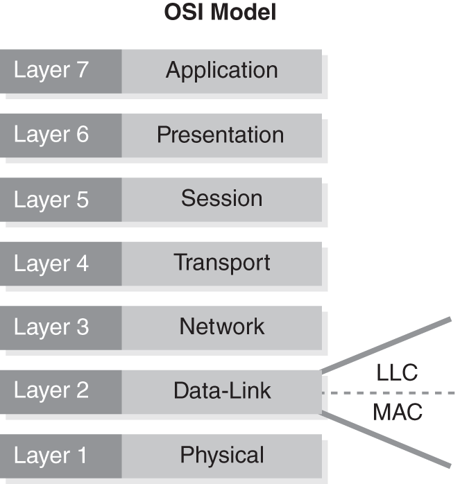
FIGURE 5-4 The OSI Reference Model.
MAC Address Database for LAN Switches
The MAC address is a unique identifier of a network device. Each MAC address is assigned by the vendor of the device and is associated with the network interface card (NIC). A MAC address is 48 bits in length and is identified as 12 hexadecimal digits. The first six hexadecimal digits identify the manufacturer and are provided by the IEEE (formerly known as the Institute of Electrical and Electronics Engineers). The last six hexadecimal digits identify the interface, like a serial number, and are provided by the vendor. A MAC address is burned into read-only memory (ROM) and is, therefore, considered permanent to the device. MAC addresses are written in this format:
MM:MM:MM:SN:SN:SN
When a device is powered up, the MAC address is sent out on the network connection, or the wire. The switch adds the MAC address and the port number on which it received the information to its MAC address table. The switch uses this table when it needs to communicate with a specific device. When the switch receives a communication request, it looks for the MAC address in its table and sends the communication out through the port identified in the table.
IEEE
IEEE is a professional not-for-profit organization designed to foster technical innovation. It was founded in 1884 in New York. The organization develops standards through the IEEE Standards Association (IEEE-SA) for information technology, power, transportation, information assurance, and other technologies and sciences. The IEEE 802 series of standards that specifically address local and metropolitan area networks are:
- IEEE 802.1—Bridging and Management
- IEEE 802.2—Logical Link Control
- IEEE 802.11—Wireless
- IEEE 802.15—Wireless Personal Area Networks
- IEEE 802.16—Broadband Wireless Metropolitan Area Networks
MAC spoofing is done to bypass a network access control or to identify a system as one that has already been authorized by the access control. For example, a specific network allows only a certain set of MAC addresses. An attacker can find an approved MAC address and change his or her system to match it. This will allow the attacker to gain access to your network.
Defining Broadcast Domains
Broadcast domains fall within the Data Link Layer and allow network devices to broadcast their MAC addresses to everyone on that LAN. By limiting the number of devices on a domain, you limit the number of network devices that can talk to one another without a switch.
IEEE 802.1q Virtual Local Area Networks (VLANs)
VLANs are defined in the IEEE 802.1q standard. VLANs can be used to segment network traffic and limit communications among multiple networks. A VLAN is a collection of devices in a single broadcast domain. VLANs are used within an organization to separate networks with different resources. For example, a company may create a VLAN specifically for the HR department so that members outside this VLAN cannot access HR resources. It becomes another mechanism for defense in depth.
VLANs may even be used on a temporary basis for projects. If an organization has contractors working on a specific application, an administrator may restrict the contractors to a particular VLAN that allows access only to the specific application. The contractors can communicate with one another and the application within the VLAN, but they cannot generate traffic to the entire network. VLANs also reduce broadcasts, and; therefore, an administrator may design the network to limit such network traffic.
Layer 3 Techniques
Layer 3 of the OSI model is referred to as the Network Layer. It is responsible for transmitting traffic from a source network to its destination on a separate network. Some of the functions provided on the Network Layer are routing, forwarding, and addressing. Routers are the most common Layer 3 devices, although other devices, such as switches and firewalls, often perform Layer 3 functions. Routers maintain routing tables, which provide instructions on how to direct traffic to reach other networks.
Access Control Lists
You can configure access control lists on a router to deny certain access to a network or deny certain traffic from traveling on a network. A router examines each packet and determines whether the packet should be forwarded or dropped based on what is stated in the access control list. For example, an administrator may use an access control list to block File Transfer Protocol (FTP) traffic on part of a network but allow Simple Mail Transfer Protocol (SMTP) traffic for email.
Route Maps
Route maps are a way for an administrator to direct traffic on a network. A route map allows an administrator to define a routing policy before the routing table on the router is referenced. Creating a route map is sometimes called “policy-based routing.” An administrator sets a policy that states “if . . . then.” A route map can use multiple policies requiring that multiple matches of packets must occur before routing changes occur.
ACLs can be used to match specific policies. Route maps are similar to ACLs in that they are an ordered sequence of events resulting in either a permit or deny permission. A route map and an ACL are scanned in a specific order until a match occurs. A route map may use an ACL in order to match the specific criteria.
When a route map is applied to an interface and tested against specific criteria and the criteria matches, an action is taken. These actions can be used to modify the packet or modify the route. For example, a route map would be used to ensure only traffic with an internal IP address (192.168.1.X) is allowed out of a specific interface. If an IP address that does not match (192.168.5.X) is on the network, the route map’s action would be to drop the packet. In this case, you can use a route map to ensure that IP addresses within a certain range do not leave the network.
Disabling IP Routing for Complete IP Traffic Isolation
In certain situations, disabling an entire IP network may be a necessary step. For instance, there may be a virus on the human resources network. Instead of allowing the virus to spread to other networks such as engineering or finance, an administrator may disable the network altogether.
 NOTE
NOTE
In practice, the CSO often delegates this emergency disconnect authority to individual members of the information security team. Providing trusted team members with this authority reduces the time to respond to a security incident in progress.
CEO/CIO/CSO Emergency Disconnect Prime Directive
Executives within an organization may take it upon themselves to remove any connection that their organization has to outside networks. For example, if an organization is being bombarded with denial of service (DoS) attacks, instead of trying to address each attack individually, the chief security officer (CSO) may decide to cut the connection so that the organization’s network can be restored internally and an assessment of the damage can be made.