
9. Working with Perspective Drawing
This lesson will take approximately an hour and a half to complete. If needed, remove the previous lesson folder from your hard disk and copy the Lesson09 folder onto it.
![]()

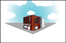
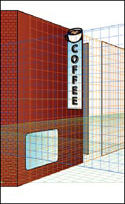
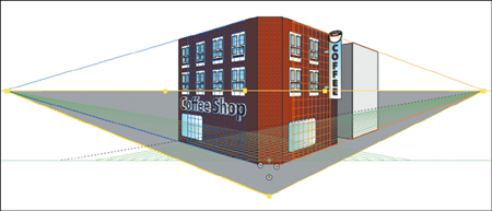
In Adobe® Illustrator® CS5, you can easily draw or render artwork in perspective using the Perspective Grid. The Perspective Grid allows you to approximately represent a scene on a flat surface, as it is naturally perceived by the human eye. For example, you can render a road or a pair of railway tracks, which seem to meet or vanish in the line of vision.
Getting started
You’ll explore working with the Perspective Grid, adding content to it, and editing on the Perspective Grid.
Before you begin, you’ll restore the default preferences for Adobe Illustrator. Then you’ll open the finished art file for this lesson to see what you’ll create.
1. To ensure that the tools and panels function as described in this lesson, delete or rename the Adobe Illustrator CS5 preferences file. See “Restoring default preferences” on page 3.
2. Start Adobe Illustrator CS5.
Note
If you have not already done so, copy the resource files for this lesson onto your hard disk from the Lesson09 folder on the Adobe Illustrator CS5 Classroom in a Book CD. See “Copying the Classroom in a Book files” on page 2.
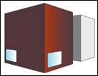
3. Choose File > Open, and open the L9end_1.ai file in the Lesson09 folder, located in the Lessons folder on your hard disk.
4. Choose View > Zoom Out to make the finished artwork smaller if you want to leave it on your screen as you work. (Use the Hand tool (![]() ) to move the artwork where you want it in the window.) Leave the file open for reference, or choose File > Close.
) to move the artwork where you want it in the window.) Leave the file open for reference, or choose File > Close.
5. Choose File > Open, and open the L9start_1.ai file in the Lesson09 folder, located in the Lessons folder on your hard disk.

6. Choose File > Save As, name the file city.ai in the Lesson09 folder. Leave the Save As Type option set to Adobe Illustrator (*.AI) (Windows) or the Format option set to Adobe Illustrator (ai) (Mac OS), and click Save. In the Illustrator Options dialog box, leave the Illustrator options at their default settings, and then click OK.
Understanding perspective
In Illustrator CS5, you can easily draw or render artwork in perspective using a feature set that works based on established laws of perspective drawing. Perspective in drawing is an approximate representation, on a flat surface, of an image as it is seen by the eye. Objects drawn in perspective are characterized primarily by the following features:
• They are drawn smaller as their distance from the observer increases.
• The perspective objects are foreshortened, which means that an object or distance appears shorter than it actually is because it is angled toward the viewer.
Understanding the Perspective Grid
The Perspective Grid allows you to approximately represent a scene on a flat surface, as it is naturally perceived by the human eye. For example, you can render a road or a pair of railway tracks, which seem to meet or vanish in the line of vision. The Perspective Grid allows you to create and render artwork in perspective.
1. Choose Essentials from the workspace switcher in the Application bar.
Note
It may be helpful to refer back to the Perspective Grid options shown in this figure as you progress through the lesson.
2. Choose View > Fit Artboard In Window.
3. Select the Perspective Grid tool (![]() ) in the Tools panel. This shows the default, two-point Perspective Grid on the artboard.
) in the Tools panel. This shows the default, two-point Perspective Grid on the artboard.
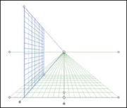
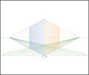
The figure below shows the Perspective Grid and its parts. As you go through this lesson, you will learn about each part.

A. Plane switching widget
B. Vertical grid extent
C. Perspective Grid ruler
D. Left vanishing point
E. Horizon line
F. Horizon height
G. Ground level
H. Extent of grid
I. Grid cell size
J. Right grid plane control
K. Horizontal grid plane control
L. Left grid plane control
M. Origin
N. Extent of grid
O. Ground level
P. Horizon level
Q. Right vanishing point
Working with the Perspective Grid
In order to begin working with content in perspective, it is helpful to see and set up the Perspective Grid the way you want.
Using a preset grid
To begin the lesson, you’ll work with the Perspective Grid, starting with some Illustrator presets.
The Perspective Grid, by default is set up as a two-point perspective. You can easily change that using presets. The Perspective Grid tool is used to edit and move the grid. You use the Perspective Grid to draw and snap content in perspective, although the grid is non-printing. Illustrator can have up to three points of perspective.
Tip
You can show the Perspective Grid without selecting the Perspective Grid tool, by choosing View > Perspective Grid > Show Grid.
1. Choose View > Perspective Grid > One Point Perspective > [1P-Normal View]. Notice that the grid changes to a one-point perspective.
A one-point perspective can be very useful for drawing roads, railway tracks, or buildings viewed so that the front is directly facing the viewer.
2. Choose View > Perspective Grid > Three Point Perspective > [3P-Normal View]. Notice that the grid changes to a three-point perspective.
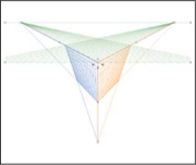
Three-point perspective is usually used for buildings seen from above or below. In addition to showing vanishing points for each wall, there is now a point showing those walls receding into the ground or high in space.
3. To return the grid back to a two-point perspective, choose View > Perspective Grid > Two Point Perspective > [2P-Normal View].
Editing the Perspective Grid
Next, you’ll learn how to edit the Perspective Grid. To edit the grid, you can either select the Perspective Grid tool or edit using the Define Grid menu item. You can make changes to the grid if you have content on the grid, although it may be easier to establish the grid settings before you add content. You can create only one grid per Illustrator document.
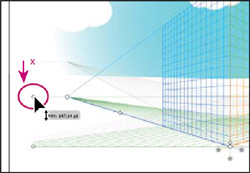
1. With the Perspective Grid showing two-point perspective and the Perspective Grid tool (![]() ) selected, drag the horizon line point down below the bottom of the blue sky to move the horizon down, as shown in the figure. The measurement label should show approximately 147 pt.
) selected, drag the horizon line point down below the bottom of the blue sky to move the horizon down, as shown in the figure. The measurement label should show approximately 147 pt.
Note
Throughout this section, the pink X in the figures shows where to drag from.
The location of the horizon line indicates the observer’s eye level.
Note
The gray lines in some of these figures indicate the initial position of the Perspective Grid, before it was adjusted.
2. With the Perspective Grid tool, drag the left ground level point up to move the whole Perspective Grid. Drag until the horizon line you adjusted in the previous step is lined up with the bottom of the blue sky.
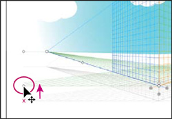
The ground level point allows you to drag the Perspective Grid to different parts of the artboard or to a different artboard altogether.
Note
As you drag the Perspective Grid by the ground level point, notice that you can move it in any direction. Make sure that it is still more or less centered horizontally on the artboard.
3. With the Perspective Grid tool, drag the horizontal grid plane control point up about 68 pt so that it’s closer to the horizon line.
Tip
The location of the ground level in relation to the horizon line will determine how far above or below eye level the object will be viewed.
4. With the Perspective Grid tool, click and drag the Vertical Grid Extent point down to shorten the vertical extent.
Making the vertical extent shorter can be a way to minimize the grid if you are drawing objects that are less precise, as you will see later in the lesson.
5. Choose File > Save. Changes you make to the Perspective Grid are saved with this document only.
Setting the grid up for your drawing is an important step. Next, you will access these changes using the Define Grid menu.
6. Choose View > Perspective Grid > Define Grid.
7. In the Define Perspective Grid dialog box, change the Units to Inches, and change the Gridline Every value to .3 in. Change the Viewing Distance to 7. in. The Viewing Distance is the distance between the observer and the scene.
Tip
After setting the Define Perspective Grid settings, you can save them as a preset to access later. In the Define Perspective Grid dialog box, change the settings, and then click the Save Preset button.
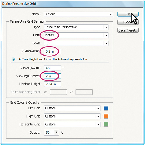
Notice that you can change the Scale of the grid, which you might want to do if real world measurements are involved. You can also edit settings like Horizon Height and Viewing Angle, which you can also edit on the artboard using the Perspective Grid tool. Leave the Grid Color & Opacity settings at their defaults. When you have finished making changes, click OK.
Tip
To learn more about the Define Perspective Grid dialog box, search for “Define grid presets” in Illustrator Help.
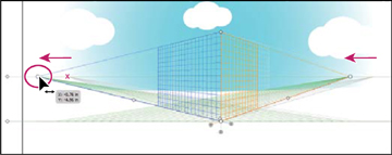
8. With the Perspective Grid tool, drag the left vanishing point about –.75 in to the left until it reaches the left horizon line point. Notice that this changes only the left (blue) grid on the two-point Perspective Grid.
9. Choose Edit > Undo Perspective Grid Edit. You are able to undo most changes made to the Perspective Grid.

10. Choose View > Perspective Grid > Lock Station Point. This locks the left and right vanishing points so that they move together.
11. With the Perspective Grid tool, drag the left vanishing point about –.75 in to the left again, until it reaches the left Horizon Line point. Notice that this now changes both grids on the two-point Perspective Grid.
13. Choose View > Perspective Grid > Lock Grid. This option restricts the grid movement and other grid editing features that use the Perspective Grid tool. You can change only the visibility and the grid plane position, which you will work with later in this lesson.
Note
When you select another tool besides the Gradient Perspective tool, you cannot edit the Perspective Grid. Also, if the Perspective Grid is locked, you can edit it by choosing View > Perspective Grid > Define Grid.
Now that the grid is locked into the correct position, you will begin creating your cityscape by adding content to it.
Drawing objects in perspective
To draw objects in perspective, use the line group tools or rectangle group tools (except for the Flare tool), while the grid is visible. Before you begin drawing using any of these tools, you need to select a grid plane to attach the content to, using the Plane Switching Widget or keyboard shortcuts.
The Plane Switching Widget
When you select the Perspective Grid, a Plane Switching Widget also appears in the upper left corner of the Document window, by default. You can use this widget to select the active grid plane.
In Perspective Grid, an active plane is the plane on which you draw an object to project the observer’s view of that portion of the scene.
—From Illustrator Help
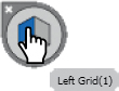
Tip
The numbers in parentheses (Left Grid(1), for instance) refer to the keyboard shortcut assigned to that grid.
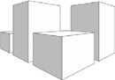
Next, you will draw several objects in perspective on the Perspective Grid.
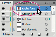
1. Click the Layers panel icon (![]() ) to expand the Layers panel. Click the eye icon (
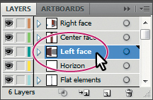
) to expand the Layers panel. Click the eye icon (![]() ) to the left of the Background layer to hide its contents on the artboard. Click to select the Left face layer so that the new content you will create is on that layer.
) to the left of the Background layer to hide its contents on the artboard. Click to select the Left face layer so that the new content you will create is on that layer.
2. Click the Layers panel icon (![]() ) to collapse the panel.
) to collapse the panel.
3. Select the Rectangle tool (![]() ) in the Tools panel.
) in the Tools panel.
4. Click the Left Grid in the Plane Switching Widget.
Whichever grid plane is selected in the widget is the grid plane on the Perspective Grid to which you’ll add content.

Note
With practice, you’ll develop the habit of checking which grid plane is active before drawing or adding content.
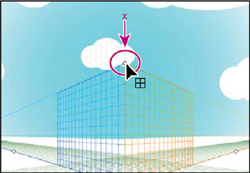
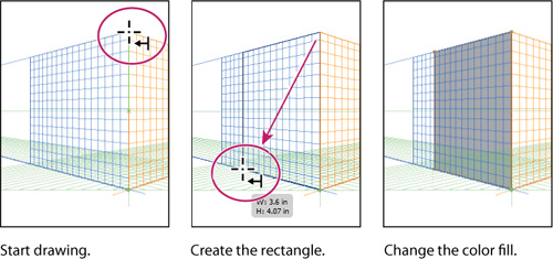
5. Position the pointer over the top of the Perspective Grid where the two planes meet. Notice the cursor (![]() ) has an arrow pointing to the left, indicating that you are about to draw on the left grid plane. Drag down and to the left, to the bottom orthogonal line, as shown in the figure. Note that it’s okay if your measurements are a little different from those shown.
) has an arrow pointing to the left, indicating that you are about to draw on the left grid plane. Drag down and to the left, to the bottom orthogonal line, as shown in the figure. Note that it’s okay if your measurements are a little different from those shown.
Tip
When drawing in perspective, you can still use the usual keyboard shortcuts for drawing objects, such as Shift-drag or Alt-drag.
When drawing on the grid plane, objects do not snap to the grid lines by default. However, smart guides do help to snap to corners and edges.
6. With the rectangle selected, change the Fill color in the Control panel to medium gray (C=0, M=0, Y=0, K=40).
Next, you will draw another rectangle to create the other side of a building, this time snapping it to the Perspective Grid.
7. Choose View > Perspective Grid > Snap To Grid.
8. Press Ctrl++ (Windows) or Cmd++ (Mac OS) twice to zoom into the Perspective Grid. Snapping to the grid doesn’t work if you are zoomed out too far.
9. Click the Layers panel icon (![]() ) to expand the Layers panel. Click to select the layer named Right face so that the new content is on that layer.
) to expand the Layers panel. Click to select the layer named Right face so that the new content is on that layer.
Note
To learn more about working with layers see Lesson 8, “Working with Layers.”
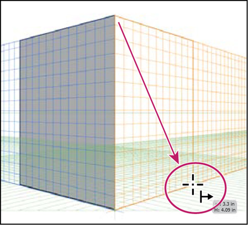
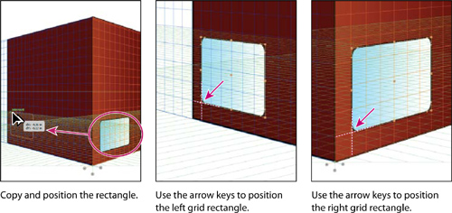
10. With the Rectangle tool still selected, click Right Grid(3) in the Plane Switching Widget, to draw in perspective on the right grid plane. Notice that the cursor (![]() ) now has an arrow pointing to the right, indicating that you are about to draw on the right grid plane. Drag down and to the right, starting at the same top point as for the last rectangle you drew. When the measurement label shows a width of approximately 3.3 in and the pointer reaches the bottom of the right grid plane, release the mouse button.
) now has an arrow pointing to the right, indicating that you are about to draw on the right grid plane. Drag down and to the right, starting at the same top point as for the last rectangle you drew. When the measurement label shows a width of approximately 3.3 in and the pointer reaches the bottom of the right grid plane, release the mouse button.
11. With the rectangle selected, change the Fill color in the Control panel to a light gray (C=0, M=0, Y=0, K=10).
12. Click the X in the upper-left corner of the Plane Switching Widget to hide the Perspective Grid and see your artwork.
Tip
You can also choose View > Perspective Grid > Hide Grid to hide the grid.
13. Choose View > Fit Artboard In Window.
Next, you will draw a rectangle that will serve as a door for the building. But first you must show the grid again, to continue drawing in perspective.
14. Press Shift+Ctrl+I (Windows) or Shift+Cmd+I (Mac OS) to show the grid.
Tip
You can also show the Perspective Grid by selecting the Perspective Grid tool, or choosing View > Perspective Grid > Show Grid.
15. Select the Rounded Rectangle tool (![]() ) in the Tools panel by holding down the Rectangle tool (
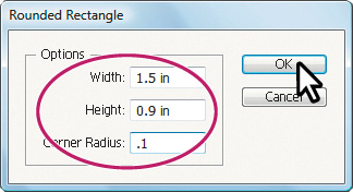
) in the Tools panel by holding down the Rectangle tool (![]() ) and positioning the pointer over the center of the rectangle you just created. Click once to open the Rectangle dialog box. Change the Width to 1.5 in and the Height to .9 in. Change the Corner Radius to .1 in, and then click OK. This will be a window in the building.
) and positioning the pointer over the center of the rectangle you just created. Click once to open the Rectangle dialog box. Change the Width to 1.5 in and the Height to .9 in. Change the Corner Radius to .1 in, and then click OK. This will be a window in the building.
16. Press Ctrl++ (Windows) or Cmd++ (Mac OS) three times to zoom in.
17. Select the Selection tool (![]() ), and drag the rectangle down and to the left, to position it at the bottom left of the light gray rectangle.
), and drag the rectangle down and to the left, to position it at the bottom left of the light gray rectangle.
If you use the Selection tool to drag an object that was drawn in perspective, it maintains its original perspective, but it doesn’t change to match the Perspective Grid.
18. Choose Edit > Undo Move to return it to its original position.
Selecting and transforming objects in perspective
You can select objects in perspective using the Perspective Selection tool (![]() ). The Perspective Selection tool uses the active plane settings to select the objects.
). The Perspective Selection tool uses the active plane settings to select the objects.
Next you will move and resize the rectangle you just drew.
1. Select the Perspective Selection tool (![]() ) in the same tools group as the Perspective Grid tool in the Tools panel. Drag the rounded rectangle down and to the left, in the lower-left corner of the light gray rectangle.
) in the same tools group as the Perspective Grid tool in the Tools panel. Drag the rounded rectangle down and to the left, in the lower-left corner of the light gray rectangle.

Notice that it snaps to the grid as you drag it.
2. With the rectangle still selected, change the Fill color in the Control panel to the window gradient.
3. With the Perspective Selection tool still selected, click the dark gray rectangle on the left grid plane to select it. Notice that the left grid plane is now selected in the Plane Switching Widget.

4. Select the Zoom tool (![]() ) in the Tools panel and drag a marquee across the lower-left corner of the medium-gray rectangle on the left grid plane.
) in the Tools panel and drag a marquee across the lower-left corner of the medium-gray rectangle on the left grid plane.
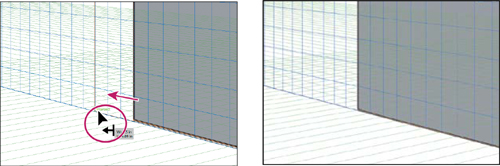
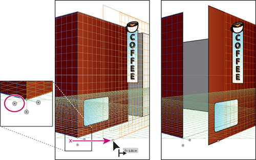
5. Select the Perspective Selection tool, then drag the lower-left corner up and to the left, following the bottom grid plane line that leads to the left vanishing point. See the figure below for help. When the measurement label shows a width of about 4.5 in, release the mouse button.
Tip
You can open the Transform panel (Window > Transform) and make the height of both rectangles the same in the Transform panel.
Note
The size does not have to match exactly, as long as the shape is snapped to the Perspective Grid. The height of your rectangles may be different than what you see in the figure.
Next, you will duplicate an object in perspective, as well as move an object perpendicular to an existing object.
6. Choose View > Fit Artboard In Window.
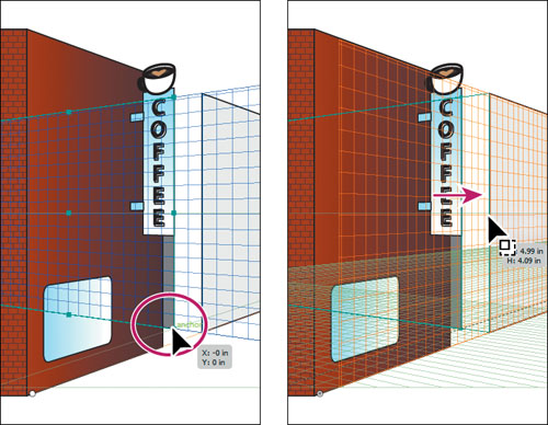
7. With the Perspective Selection tool selected, holding down Alt+Shift (Windows) or Option+Shift (Mac OS), drag to the right the light gray rectangle on the right grid plane. When the measurement label shows a distance (dX) of approximately 4.75 in, release the mouse button and then the modifier keys.
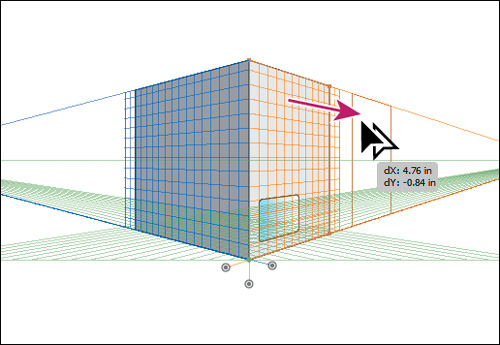
You will use this copy as the face of another building. As with other types of drawings, the Alt or Option key duplicates the object and the Shift key constrains the movement.
With the rectangle copy in place and in perspective, you will now adjust the Perspective Grid so that the grid pattern covers the new shape. You’ll do this by editing the grid extent.
8. Select the Perspective Grid tool (![]() ) in the Tools panel.
) in the Tools panel.
9. Press Ctrl++ (Windows) or Cmd++ (Mac OS) twice to zoom in.
Notice that the grid pattern in the Perspective Grid starts to expand to the right and left.
10. Choose View > Perspective Grid > Unlock Grid, which enables you to edit the grid.
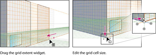
11. With the Perspective Grid tool, position the pointer over the right grid extent widget and drag to the left until it reaches the right edge of the copied rectangle, as shown in the figure below. The pink x in the figure below indicates the approximate starting location of the right grid extent widget.
Next, you will adjust the grid cell size.
12. Drag the grid cell widget down a bit until the grid cell size becomes smaller.
Notice that if you drag too far down, the left and right extent of the grid moves away from its accompanying vanishing point. Dragging up would increase the size of the grid cells.
Note
Gridlines are set to display on-screen when there is a 1-pixel gap in them. Progressive zooming in will bring in to view more gridlines that are closer to the Vanishing Point.
13. Select the Selection tool, and click to select the medium-gray rectangle on the left grid plane. Change the Fill color in the Control panel to the building face 1 color. Click to select the second rectangle you created (the other face of the same building) and change the color in the Control panel to building face 2.
14. Choose File > Save.
Now that the copied rectangle is in place and the grid cells display correctly, you will copy the rectangle on the left grid plane so that it becomes the left face of the newly-copied rectangle. Next, you will see how to move an object parallel to its current location.
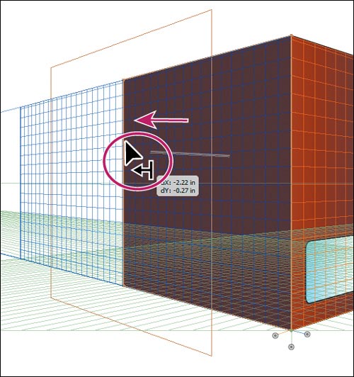
1. Select the Perspective Selection tool (![]() ) in the Tools panel. Click to select the red-colored rectangle on the left grid plane. Holding down the number 5 key, drag the rectangle to the left a bit. Release the mouse and then the 5 key.
) in the Tools panel. Click to select the red-colored rectangle on the left grid plane. Holding down the number 5 key, drag the rectangle to the left a bit. Release the mouse and then the 5 key.
This action moves the object in parallel to its current location.
2. Choose Edit > Undo Perspective Move.
3. With the Perspective Selection tool selected, hold down the Alt (Windows) or Option (Mac OS) key and the number 5 key, and drag the same rectangle to the right. Drag to position it as the left face of the second building. When in position, release the mouse and then the modifier keys.
This duplicates the object and places it at the new location without changing the original object. In Draw Behind mode this action, creates the object behind the original object.
4. With the new copy still selected, choose Object > Arrange > Send To Back. Change the Fill color of the new object in the Control panel to a medium gray.
Next, you will make a copy of the rounded rectangle “window,” and then move it to the left grid plane of the red building by pressing a keyboard shortcut to switch planes while dragging.
5. With the Perspective Selection tool selected, select the blue window on the right face of the building. Choose Edit > Copy, and then Edit > Paste In Front.
6. Drag a copy of the rounded rectangle window to the left with the Perspective Selection tool. As you drag, press, then release number 1 to switch the window to the left grid plane. Drag the window to the lower-left corner of the red rectangle on the left (which is the left side of the red building).
Note
While dragging you may need to press the number 1 a few times.
7. Choose Edit > Cut.
8. Click the Layers panel icon (![]() ) to expand the Layers panel. In the Layers panel make sure that the Left face layer is selected. Click the Layers panel icon to collapse the panel again.
) to expand the Layers panel. In the Layers panel make sure that the Left face layer is selected. Click the Layers panel icon to collapse the panel again.
9. Choose Edit > Paste In Front.
Note
If the rounded rectangle doesn’t appear on top of all other objects, choose Object > Arrange > Bring To Front.
10. With the rounded rectangle still selected, press the right arrow key, and then the up arrow key. Notice that pressing the arrow keys snaps the rounded rectangle to the Perspective Grid. Using the arrow keys, position the window in the lower-left corner of the red rectangle, as shown in the figure.
Note
The grid size determines the distance an object is moved using the arrow keys.
11. Click to select the original rounded rectangle on the right grid plane so that it is the only thing selected. Position it on the same grid lines (relatively) as the copy, using the arrow keys to snap it to the grid, as shown in the figure.
12. Press Ctrl+Shift+I (Windows) or Cmd+Shift+I (Mac OS) to temporarily hide the Perspective Grid.
13. Choose Select > Deselect, then File > Save.
Attaching objects to perspective
If you have already created objects, Illustrator provides an option to attach the objects to an active plane on the Perspective Grid. You will now add an existing sign for a coffee shop to one of the sides of a building.
1. Choose View > Perspective Grid > Show Grid to show the grid.
2. Choose View > Fit All In Window to see the two artboards.
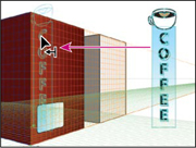
3. Select the Selection tool (![]() ) and click to select the Coffee sign on the artboard on the right. Drag the sign close to the right of the gray building you’ve created in perspective. After you’ve placed the sign, click once somewhere on a blank area of the main artboard with the grid. This puts the focus on the artboard with the Perspective Grid.
) and click to select the Coffee sign on the artboard on the right. Drag the sign close to the right of the gray building you’ve created in perspective. After you’ve placed the sign, click once somewhere on a blank area of the main artboard with the grid. This puts the focus on the artboard with the Perspective Grid.
4. Choose View > Fit Artboard In Window.
5. Press Ctrl++ (Windows) or Cmd++ (Mac OS) twice to zoom into the Perspective Grid and artwork.
Next, you will add the selected sign to the right side of the red building, and put it into perspective along with the rest of the artwork on the main artboard.
6. Select the Perspective Selection tool (![]() ) in the Tools panel. Click the Left Grid(1) in the Plane Switching Widget to make sure that the sign will be added to the left plane grid.
) in the Tools panel. Click the Left Grid(1) in the Plane Switching Widget to make sure that the sign will be added to the left plane grid.
Tip
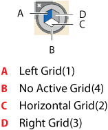
You can also select the active plane by pressing keyboard shortcuts: 1=Left Grid, 2=Horizontal Grid, 3=Right Grid, and 4=No Active Grid.
Note
This is an important step that can be easily forgotten!
7. With the Perspective Selection tool, drag the sign so that the top of the sign aligns with the top of the Vertical Grid Extent.
The artwork is added to the grid that is selected in the Plane Switching Widget.
Tip
Instead of dragging the object onto the plane using the Perspective Selection tool, you can also select the object with the Perspective Selection tool, choose the plane using the Plane Switching Widget, and then choose Object > Perspective > Attach to Active Plane.
Note
The coffee sign is a group of objects. You can just as easily attach a single object to the Perspective Grid.
8. With the sign still selected, choose Edit > Cut.
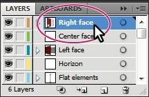
9. Click the Layers panel icon (![]() ) on the right side of the workspace to expand the Layers panel. Click to select the Right face layer. Choose Edit > Paste In Place. This pastes the sign on the Right face layer.
) on the right side of the workspace to expand the Layers panel. Click to select the Right face layer. Choose Edit > Paste In Place. This pastes the sign on the Right face layer.
10. Click the Layers panel icon to collapse the panel.
With the coffee sign attached to the left grid plane, you will now move it perpendicular to its current location, so that it is on the right side of the building.
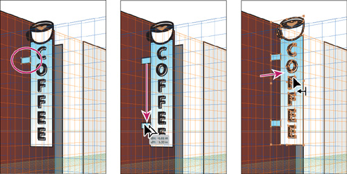
11. With the Perspective Selection tool, hold down the number 5, and drag the coffee sign to the right until it reaches the right side of the red rectangle, as shown in the figure. Release the mouse button and then the modifier key.
12. With the Perspective Selection tool, hold down the Shift key and drag the bottom, middle point of the sign up to make it smaller. When the measurement label shows a Height of about 2.4 or 2.5 inches, stop dragging. Release the mouse button, and then the Shift key.
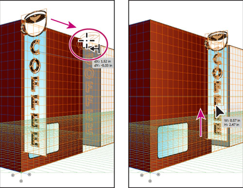
Drag the sign into position.
Scale the sign.
Note
If your sign is too close or too far from the red building after resizing, then you can drag to position it better using the Perspective Selection tool.
13. Choose Select > Deselect, then File > Save.
Editing planes and objects together
You can edit the grid planes in perspective either before or after there is artwork on them in perspective. You can move objects perpendicularly by dragging them or move a grid plane using grid plane controls to move objects perpendicularly.
Next, you will edit the grid planes and the artwork.
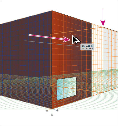
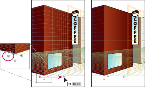
1. With the Perspective Selection tool (![]() ) still selected, drag the right grid plane control to the right until approximately D:1in appears in the measurement label, as shown in the figure. This moves the right grid plane, but not the objects on it.
) still selected, drag the right grid plane control to the right until approximately D:1in appears in the measurement label, as shown in the figure. This moves the right grid plane, but not the objects on it.
Note
Throughout this section, a pink X in the figures shows where to drag from.
2. Choose Edit > Undo Perspective Grid Edit to return the grid plane to its original position.
3. With the Perspective Selection tool still selected, hold down the Shift key, drag the right grid plane control to the right until the measurement label shows about 1 in. Release the mouse button, and then the Shift key.
The Shift key moves the grid plane and the artwork on the grid perpendicular to their original positions.
Tip
If you select an object or objects on the active grid plane, and then drag the grid plane control while holding down the Shift key, only selected objects move with the grid plane.
Tip
Dragging a grid plane control while pressing Shift+Alt (Windows) or Shift+Option (Mac OS) drags a copy of the objects with the grid plane.
Dragging a grid plane control is not very precise. For more precision, you can move the right grid plane control according to values you enter, which you will do next.
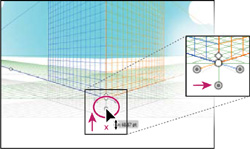
4. Double-click the same right grid plane control you just dragged. Change the Location to .5 in, and then select Move All Objects. Click OK.

In the Right Vanishing Plane dialog box, the Do Not Move option allows you to move the grid plane and not the objects on it. Copy All Objects allows you to move the grid plane and bring a copy of the objects on the grid plane with it.
The location starts at 0, which is at the station point. The station point is indicated by the small green diamond above the horizontal grid control (an arrow is pointing to it in the figure).
Next, you will move the left grid plane using the same method.
5. Double-click the left grid plane control. Change the Location to –.4 in, and then select Move All Objects. Click OK.

The grid planes move to the right when you enter a positive value and to the left when you enter a negative value.
Now the grid planes and objects are where they need to be, except for the coffee sign and the left side of the second, gray building, which you will move later. You will now add a flat corner rectangle to the red building.
6. Click the Layers panel icon (![]() ) on the right side of the workspace to expand the Layers panel. Click to select the Center face layer.
) on the right side of the workspace to expand the Layers panel. Click to select the Center face layer.
7. Click the Layers panel icon to collapse the panel.
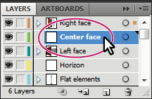
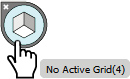
8. Select the Rectangle tool (![]() ) from the same group as the Rounded Rectangle tool in the Tools panel. Click No Active Grid in the Plane Switching Widget. This allows you to draw without perspective.
) from the same group as the Rounded Rectangle tool in the Tools panel. Click No Active Grid in the Plane Switching Widget. This allows you to draw without perspective.
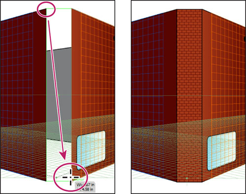
9. Starting from the upper-right corner of the red rectangle on the left grid plane, drag down and to the right to the lower-left corner of the red rectangle on the right grid plane, as shown in the figure below.
Note
The corners of the rectangles may not line up perfectly. If you want to ensure that they do, you can select the Perspective Selection tool and select each rectangle. Then, with the smart guides on, the corner points to snap to each other.
10. With the rectangle still selected, change the Fill color to building corner in the Control panel.
11. Choose Select > Deselect, then File > Save.
Now that the red building is taking shape, you will reposition the coffee sign, and draw some rectangles to attach the sign the face of the building. This will require that you move a grid plane to match the coffee sign.
1. Select the Perspective Selection tool (![]() ) in the Tools panel. Click to select the Coffee sign. Choose Object > Perspective > Move Plane To Match Object.
) in the Tools panel. Click to select the Coffee sign. Choose Object > Perspective > Move Plane To Match Object.
This moves the left plane grid to match the perspective of the sign. This allows you to draw or add more content in the same plane as the coffee sign.
Note
If you wanted to simply move the coffee sign in perspective with the Perspective Selection tool, you would not have to move the grid plane to match it.
2. Choose Select > Deselect. Select the Zoom tool (![]() ) in the Tools panel and drag a marquee around the coffee sign to zoom into it.
) in the Tools panel and drag a marquee around the coffee sign to zoom into it.
3. Making sure that the Left Grid is selected in the Plane Switching Widget, select the Rectangle tool in the Tools panel.
Tip
You can hide or reposition the Plane Switching Widget by double-clicking the Perspective Grid tool (![]() ) or the Perspective Selection tool (
) or the Perspective Selection tool (![]() ) and then changing the options in the Perspective Grid Options dialog box.
) and then changing the options in the Perspective Grid Options dialog box.
Next, you will draw some rectangles between the sign and the building, to attach the sign to the building.
4. Starting on the left edge of the coffee sign, drag down and to the left to create a small rectangle, as shown in the figure below. This acts as one attachment point for the sign.
5. With the rectangle still selected, change the Fill color in the Control panel to light blue.
6. Select the Perspective Selection tool (![]() ) in the Tools panel. Holding down Shift+Alt (Windows) or Shift+Option (Mac OS), drag the new rectangle down, to create a copy towards the bottom of the sign. Release the mouse button and then the modifier keys. You may need to zoom in further.
) in the Tools panel. Holding down Shift+Alt (Windows) or Shift+Option (Mac OS), drag the new rectangle down, to create a copy towards the bottom of the sign. Release the mouse button and then the modifier keys. You may need to zoom in further.
7. With the new rectangle copy still selected, Shift-click the first rectangle you just drew and the coffee sign and then choose Object > Group.
8. Holding down the Shift key, drag the sign group to the right so that it looks like it’s attached to the building. The sign position does not have to match the figure below exactly.
Tip
Effects can be applied to objects in perspective. For instance, you could apply a 3D extrude effect (Effect > 3D > Extrude & Bevel) to the coffee sign group.
9. Choose View > Fit Artboard In Window.
10. With the Perspective Selection tool, click to select the red rectangle representing the left side of the building. Choose Object > Perspective > Move Plane To Match Object.
Tip
To return the left grid plane to the building face, you can also double-click the left grid plane control and change the Location to –.4 in, select Do Not Move, and then click OK.
11. Choose Select > Deselect.
Next, you’ll move the medium gray rectangle that represents the left part of the second building into the proper position. In order to see a grid plane as you drag the rectangle into position, you can temporarily align the left grid plane to the object.
12. Press Ctrl++ (Windows) or Cmd++ (Mac OS) twice to zoom into the Perspective Grid and artwork.
13. With the Perspective Selection tool, click to select the medium gray rectangle behind the coffee sign, as shown in the figure below.
Note
If it is difficult selecting the medium gray rectangle behind the coffee sign, you may need to choose View > Outline to select it by the edge, and then choose View > Preview.
14. Holding down the Shift key, position the pointer over the lower-right corner point on the medium gray rectangle. Release the Shift key.
The left grid plane is temporarily aligned with the medium gray rectangle, which means that you can draw or add content to the grid on that plane. You can position the pointer over any of the corner points while holding the Shift key to do the same thing.
Note
Smart guides need to be turned on (View > Smart Guides) in order for you to position the plane automatically, using the Shift key.
15. Drag the middle, right point on the medium gray rectangle to the right, so that it aligns with the edge of the light gray rectangle.
Note
You do not need to position the grid plane in order to resize or reposition an object in perspective, using the Perspective Selection tool.
After dragging the rectangle, notice that the left grid plane returns to its original position. This is a way to temporarily reposition a grid plane.
16. Choose Select > Deselect, and then File > Save.
Automatic plane positioning
Using the automatic plane positioning options, you can select to move the active plane temporarily when you mouse over the anchor point or gridline intersection point by pressing the Shift key.

The automatic plane positioning options are available in the Perspective Grid Options dialog box. To display this dialog box, double-click the Perspective Grid tool (![]() ) or the Perspective Selection tool (
) or the Perspective Selection tool (![]() ) in the Tools panel.
) in the Tools panel.
—From Illustrator Help
Adding and editing text in perspective
You cannot directly add text to a perspective plane when the grid is visible. However, you can bring text into perspective after creating it in normal mode. Next, you will add a sign above one of the windows.
1. Click the Layers panel icon (![]() ) to expand the Layers panel. In the Layers panel make sure that the Left face layer is selected. Click the Layers panel icon to collapse the panel again.
) to expand the Layers panel. In the Layers panel make sure that the Left face layer is selected. Click the Layers panel icon to collapse the panel again.

Note
You may want to zoom into the artwork by pressing Ctrl++ (Windows) or Cmd++ (Mac OS) twice.
2. Select the Type tool (![]() ) in the Tools panel.
) in the Tools panel.
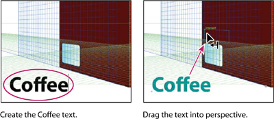
3. Click in a blank space on the artboard and type Coffee.
4. Select the text with the Type tool and change the Font to Myriad Pro, the Font Size to 48. pt, and the Font Style to Bold in the Control panel.
Note
If you don’t see the font formatting options in the Control panel, click the word Character in the Control panel to reveal the Character panel.
5. Select the Perspective Selection tool (![]() ) in the Tools panel. Press the number 1 on your keyboard to select the Left Grid, and then drag the text above the rounded rectangle window on the left wall.
) in the Tools panel. Press the number 1 on your keyboard to select the Left Grid, and then drag the text above the rounded rectangle window on the left wall.
Next, you will edit the text while it is in perspective.
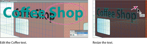
6. With the text object still selected, double-click the text with the Perspective Selection tool. This enters isolation mode, allowing you to edit the text instead of the perspective object.
Tip
You can also enter isolation mode to edit text by clicking the Edit Text button (![]() ) in the Control panel.
) in the Control panel.
7. In isolation mode, the Type tool (![]() ) is selected automatically. Insert the cursor after the “Coffee” text, press the spacebar, and then type Shop. Press the Escape key twice to exit isolation mode and return to the perspective object.
) is selected automatically. Insert the cursor after the “Coffee” text, press the spacebar, and then type Shop. Press the Escape key twice to exit isolation mode and return to the perspective object.
Tip
To exit isolation mode, you can also click the gray arrow twice that appears below the document tab at the top of the Document window.
8. Using the Perspective Selection tool, hold down the Shift key and drag the upper-right corner of the text object up and to the right, to make it a bit larger. We made the width approximately 3.8 in. Release the mouse button, and then the modifier key.
9. Click the Graphic Styles panel icon (![]() ) on the right side of the workspace. With the text object selected, click the graphic style named “Text” in the Graphic Styles panel. Click the Graphic Styles panel icon to collapse the panel.
) on the right side of the workspace. With the text object selected, click the graphic style named “Text” in the Graphic Styles panel. Click the Graphic Styles panel icon to collapse the panel.
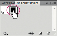
This applies a 3D Extrude effect as well as strokes, fills, and a drop shadow effect to the text object. You can apply many kinds of effects, strokes, fills, and more to text in perspective.
Note
To learn more about working with graphic styles, see Lesson 13, “Applying Appearance Attributes and Graphic Styles.”
10. Choose View > Fit Artboard In Window.
11. Press Ctrl+Shift+I (Windows) or Cmd+Shift+I (Mac OS) to temporarily hide the Perspective Grid.
12. Choose Select > Deselect, and then File > Save.

Working with symbols in perspective
Adding symbols to a perspective plane when the grid is visible is a great way to add repeating items, such as windows. Like text, you can bring symbols into perspective after creating them in normal mode. Next, you will add some windows to the red building from a window symbol that is already created.
Note
To learn more about symbols, see Lesson 14, “Working with Symbols.”
Adding Symbols to the Perspective Grid
1. Press Ctrl+Shift+I (Windows) or Cmd+Shift+I (Mac OS) to show the Perspective Grid and then press Ctrl++ (Windows) or Cmd++ (Mac OS) twice to zoom into the Perspective Grid and artwork.
2. Select the Perspective Selection tool (![]() ), and then click the left side of the red building on the left grid plane.
), and then click the left side of the red building on the left grid plane.
Note
Clicking the left side of the building does two things: it switches planes in the Plane Switching Widget to the left grid plane, and it selects the Left face layer in the Layers panel (because that is the layer that the red rectangle is on).
Next, you’ll attach a window to the left plane grid and put it on the Left face layer.
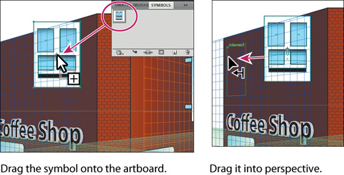
3. Click the Symbols panel icon (![]() ) on the right side of the workspace to expand the Symbols panel. Drag the window1 symbol from the Symbols panel onto the left face of the red building. Notice that it is not in perspective.
) on the right side of the workspace to expand the Symbols panel. Drag the window1 symbol from the Symbols panel onto the left face of the red building. Notice that it is not in perspective.
4. Drag the window with the Perspective Selection tool to above the Coffee Shop text to attach it to the left grid plane. Then, drag the window towards the upper-left corner of the left side of the red building. Snap it to the grid.
Note
Make sure that the window is close to the top of the building, since you will be adding another row of windows below this one. See the figure for position.
Transforming Symbols in perspective
1. With the Perspective Selection tool (![]() ), double-click the window on the left grid plane. A dialog box appears, telling you that you are about to edit the symbol definition. This means that if you edit the content, it will change all of the window symbols on the artboard, which are called instances. Click OK.
), double-click the window on the left grid plane. A dialog box appears, telling you that you are about to edit the symbol definition. This means that if you edit the content, it will change all of the window symbols on the artboard, which are called instances. Click OK.
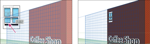
2. Select the Selection tool (![]() ) in the Tools panel. Choose Select > All On Active Artboard. Holding down the Shift key, drag the lower-right corner of the window up and to the left, to make it smaller. When the measurement label shows a width of about .6 in, release the mouse button and then the Shift key.
) in the Tools panel. Choose Select > All On Active Artboard. Holding down the Shift key, drag the lower-right corner of the window up and to the left, to make it smaller. When the measurement label shows a width of about .6 in, release the mouse button and then the Shift key.
3. Press the Escape key to exit isolation mode. Notice that the window is now smaller.
The window on the grid needs be aligned with the rounded rectangle window shape at the bottom of the building face. To do that, you will reposition the grid origin. If you shift the origin, the x and y coordinates of the horizontal plane and the x coordinate of vertical planes are affected. When you select an object in perspective while the grid is visible, the x and y coordinates displayed in the Transform and Info panels change with the shift in the origin.
4. Select the Perspective Selection tool in the Tools panel. Click to select the rounded rectangle window on the left side of the red building, below the Coffee Shop text. Choose Window > Transform to open the Transform panel. Notice the X and Y measurements.
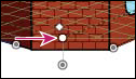
5. Select the Perspective Grid tool (![]() ) in the Tools panel. Position the pointer over the origin point at the bottom of the center, brick face of the red building on the grid. The cursor (
) in the Tools panel. Position the pointer over the origin point at the bottom of the center, brick face of the red building on the grid. The cursor (![]() ) will show a small circle next to it. Drag the origin point to the lower-left corner of the red rectangle of the left grid plane.
) will show a small circle next to it. Drag the origin point to the lower-left corner of the red rectangle of the left grid plane.
Tip
You can show rulers on the Perspective Grid by choosing View > Perspective Grid > Show Rulers. This shows you a ruler on each grid plane in the units set in the Define Grid dialog box.
This sets the 0,0 point (origin) for the x and y coordinates of the horizontal plane and the x coordinate of vertical planes to that new origin point.
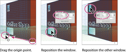
6. Select the Perspective Selection tool in the Tools panel. Click to select the rounded rectangle window and then click the lower-left reference point in the Transform panel (![]() ). Change the X value to .3 in.
). Change the X value to .3 in.
7. Select the window above the rounded rectangle and change the X value to .3 in. This will align the left edge of both objects to each other at a distance you specified from the origin.
Note
To reset the origin point, you can select the Perspective Grid tool in the Tools panel, and double-click the origin point.
9. Holding down the Shift+Alt (Windows) or Shift+Option (Mac OS) keys, drag the window to the right until the measurement label shows approximately 1 inch for the dX. Release the mouse button, and then the keys. This creates a copy of the window in perspective.
10. Choose Object > Transform > Transform Again to repeat the transformation. Press Ctrl+D (Windows) or Cmd+D (Mac OS) once to repeat the transformation again. Notice that the copies are in perspective.
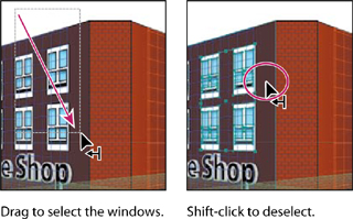
11. With the Perspective Selection tool, Shift-click the windows in a row to select them all.
Note
When you Shift-click the window(s) you may accidentally move them. If this happens, choose Edit > Undo Perspective Move and try again.
12. Holding down the Shift+Alt (Windows) or Shift+Option (Mac OS) keys, drag the selected windows down, to just above the Coffee Shop text. Release the mouse button, and then release the modifier keys. This creates a copy of the windows in perspective, making a total of eight windows.

13. Choose Select > Deselect.
14. With the Perspective Selection tool, starting above the left side of the red building, drag a marquee across the four windows on the right, above the word “Shop.” Shift-click the red rectangle on the left grid plane to deselect it.
The next step requires several key commands in a precise order, so read carefully.
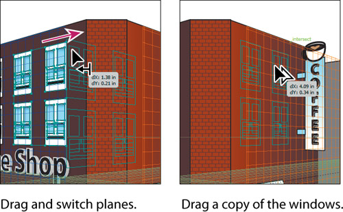
15. With the four windows selected, drag them to the right. Don’t release the mouse button yet. Press the number 3 key to switch to the right grid plane. Hold down the Alt (Windows) or Option (Mac OS) key, and continue dragging the windows close to the upper-left corner of the right side of the red building. Try to align the left edges of the windows with the round rectangle on the right grid plane. When they are in position, release the mouse button, and then the modifier key. Leave the windows selected.
The copied windows are on another layer that is beneath the rectangle on the right side of the building. You need to move the copied windows to the same layer.
16. Choose Edit > Cut.
17. Click the Layers panel icon (![]() ) on the right side of the workspace to expand the Layers panel. Click the Right face layer to select it.
) on the right side of the workspace to expand the Layers panel. Click the Right face layer to select it.
18. Choose Edit > Paste In Place.
19. Choose Select > Deselect.
20. Choose View > Fit Artboard In Window, and then choose File > Save.
Release content from perspective
There will be times when you want to use objects that are currently in perspective elsewhere or you want to detach an object from a grid plane. Illustrator allows you to release an object from the associated perspective plane and make it available as normal artwork. That’s what you’ll do next.
1. With the Perspective Selection tool (![]() ) selected, click to select the Coffee Shop text on the left side of the red building.
) selected, click to select the Coffee Shop text on the left side of the red building.
2. Choose Object > Perspective > Release With Perspective.
3. Choose Select > Deselect.
4. With the Perspective Selection tool, Shift-drag the left grid plane control to the left until the measurement label shows a distance of approximately –1 in. Release the mouse button, and then the modifier key. This shows that the Coffee Shop text does not move with the grid, since the text has been released from the grid.

5. Choose Edit > Undo Perspective Grid Edit, then choose Edit > Undo Release With Perspective.
6. In the Layers panel icon click the visibility column to the left of the Background layer to show it.
7. Choose Select > Deselect, then File > Save.

Exploring on your own
To explore more, you will create a sidewalk, and doors.
1. Click the Layers panel icon (![]() ) to expand the panel. Click the Horizon layer to select it.
) to expand the panel. Click the Horizon layer to select it.
2. Select the Rectangle tool, and press the number 2 key to select the Horizontal Grid. Position the pointer about an inch below the bottom edge of the brick building face, and drag up to the horizon line. This will be a sidewalk. Select the Perspective Selection tool (![]() ) and drag the corner points of the rectangle so that it looks similar to the gray shape beneath the buildings in the figure below.
) and drag the corner points of the rectangle so that it looks similar to the gray shape beneath the buildings in the figure below.
3. Change the Fill color of the sidewalk to a gray in the Control panel.
4. Click to select the Left face layer in the Layers panel.
5. With the Rectangle tool (![]() ), create a door for the red building on the left grid plane.
), create a door for the red building on the left grid plane.
6. Choose File > Save, and then choose File > Close.
Review questions
1 There are three preset grids. Describe briefly what each could be used for.
2 How can you show or hide the Perspective Grid?
3 Before drawing content on a grid plane, what must be done to ensure that the object is on the correct grid plane?
4 Describe the steps required to move content from one grid plane to another.
5 What does double-clicking a grid plane control allow you to do?
6 How do you move an object perpendicular to the grid?
Review answers
1. A one-point perspective can be very useful for roads, railway tracks, or buildings viewed so that the front is directly facing the viewer. Two-point perspective is useful for drawing a cube, like a building, or two roads going off into the distance and typically has two vanishing points. Three-point perspective is usually used for buildings seen from above or below. In addition to vanishing points for each wall, there is a vanishing point showing those walls receding into the ground or high in space in three-point perspective.
2. You can hide or show the Perspective Grid by selecting the Perspective Grid tool (![]() ) in the Tools panel, by choosing View > Perspective Grid > Show Grid/Hide Grid, or by pressing Ctrl+Shift+I (Windows) or Cmd+Shift+I (Mac OS).
) in the Tools panel, by choosing View > Perspective Grid > Show Grid/Hide Grid, or by pressing Ctrl+Shift+I (Windows) or Cmd+Shift+I (Mac OS).
3. The correct grid plane must be selected by choosing it in the Plane Switching Widget, by using the following keyboard commands: Left Grid (1), Horizontal Grid (2), Right Grid (3), or No Active Grid (4), or selecting content on the grid you want to choose with the Perspective Selection tool (![]() ).
).
4. With the object(s) selected, begin dragging them, without releasing the mouse button yet. Press the number 1, 2, 3, or 4 key, (depending on which grid you intend to attach the object(s) to) to switch to the grid plane of your choice.
5. Double-clicking a grid plane control allows you to move the plane. You can specify whether to move the content associated with the plane, and whether to copy the content as the plane moves.
6. With the Perspective Selection tool, hold down the number 5 key, and drag the object perpendicular to the plane.