Lithium-ion batteries for hybrid electric vehicles and battery electric vehicles
A. Perner; J. Vetter BMW Group, Munich, Germany
Abstract
This chapter discusses lithium-ion battery chemistries, designs, and trends for hybrid electric vehicles (HEVs) and battery electric vehicles (EVs). The main development focus of HEV and EV batteries is on higher energy densities, safety, lifetime, and costs. On the cell level, different cell formats and cell chemistries are discussed and the general battery pack design is highlighted. Expected future trends and developments for cathode chemistry 5 V materials and for silicon alloy anodes are discussed. For battery packs, the major focus is on lightweight construction and cost-efficient electric and electronic architectures.
8.1 Introduction and requirements for hybrid electric vehicle, plug-in hybrid electric vehicle, and electric vehicle Li-ion batteries
To reach the upcoming CO2 emission regulations the automotive industry (especially premium vehicle manufacturers) has to develop more and more electric vehicles such as hybrid electric vehicle (HEV), plug-in hybrid electric vehicle (PHEV), and electric vehicle (EV). For these automotive applications Li-ion technology is the key technology for the next several years. The main development focus of HEV and EV batteries is on higher energy densities to increase electric-driving range, safety, lifetime, reliability, and costs. On the cell level, different cell formats and cell chemistries are discussed.
8.1.1 Performance, lifetime, and cost requirements
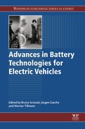
One of the main vehicle requirements for EVs, PHEVs, and HEVs is the electric-driving range and power. Typical values for energy and power on a battery and cell level to meet customers' electric-driving range are shown in Tables 8.1 and 8.2.
Table 8.1
Energy and power requirements for xEV batteries
| Battery | Energy content (kWh) | Utilization (%) | Power (kW) | P/E ratio |
| HEV | 1–3 | 40–70 | 20–60 | 30–40 |
| PHEV | 5–15 | 60–90 | 40–150 | 5–10 |
| EV | 20–50 | 80–100 | 50–350 | 3–7 |
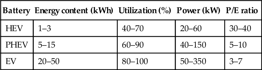
Table 8.2
Energy and power requirements for xEV cells
| Cell | Energy content (Wh) | Utilization (%) | Power | P/E ratio |
| HEV | 12–20 | 40–70 | 25–60 kW | ≈ 80 |
| PHEV | 75–180 | 60–90 | 40–150 kW | ≈ 20 |
| EV | 180–800 | 80–100 | 800–1200 W | 3–10 |
On cell level today 120–140 Wh/kg for energy density and up to 800–1500 W/kg peak discharge power density are necessary to reach the requested energy and power on battery level. Until 2020, energy densities up to 200–250 Wh/kg are expected. The cell has to be developed for cell temperatures between − 40 and + 60 °C during operation and − 40 and + 80 °C during storage.
Another important requirement is lifetime. The Li-ion cell is to be designed in such a way that full-functioning capability is ensured over at least 10 years considering customer-driving profiles. The end of life is reached when either the cell reached 80% of rated beginning-of-life capacity or 80% of beginning-of-life power. Depending on the power demand and vehicle mileage expectations, a 10-year vehicle life represents a total energy throughput of up to 800,000 kWh.
Not a technical requirement but no less important are the costs. Cost targets of €200–250 per kWh have to be met to offer EVs with reasonable price levels.
8.2 Cell designs
The cell design of automotive Li-ion cells typically comprises one or more so-called jelly rolls, which are the spirally wound positive and negative electrodes separated by a polyethylene- and/or polypropylene-based separators (see Figure 8.1).

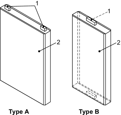
Another cell design option is the so-called stacked electrode design that is usually used in pouch cells (see Figure 8.2).

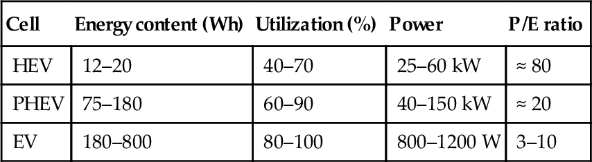
For EVs various cell formats are used. These are cylindrical (with a cylindrical hard case housing and terminal), prismatic hard case (with a prismatic hard case housing and terminal), or pouch cells (with a laminated housing consisting of compound foil and terminal) in different sizes and dimensions (see Figures 8.3–8.5). For these cell formats a DIN SPEC 91252 norm has been chosen to standardize the cell dimensions.

For safety reasons the cells are usually equipped with one or more additional safety device such as an overpressure safety device, melting fuse, overcharge, or nail-penetration safety device.
Li-ion cells usually work at a voltage of 3–4 V. They currently have a specific energy of 100–180 Wh/kg. The structure contains a graphite or oxide anode, a lithium metal oxide or olivine structure cathode, and an electrolyte solution of LiPF6 in a mixed organic solvent (e.g., ethylene carbonate, dimethyl carbonate).
8.2.1 Overview of cell chemistries
What are the advantages and disadvantages of the Li-ion technology in comparison to other technologies?
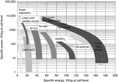
In comparison to other cell technologies, which are discussed for automotive applications such as nickel–metal hybrid, nickel–cadmium, lead–acid, or supercapacitors, the major advantage of the Li-ion technology is the high energy density with reasonable power density (see Figure 8.6). Only supercapacitors can deliver higher-power densities but they have a limited feasibility due to limited energy density (3–5 Wh/kg). Considering the combined lifetime performance of cyclic and calendrical aging, the Li-ion technology outplays the other technologies.
One of the major trade-offs of the Li-ion technology is the higher safety risk due to the high energy density and use of flammable electrolyte solutions. Here the focus on further developments is on solid or nonflammable electrolyte formulations.
In terms of cost a dramatic reduction for the Li-ion technology in automotive applications is expected. Thus, a price of less than €200 per kWh battery level within the next years is predicted. The Li-ion technology delivers the best compromise between energy density, power capability, safety, lifetime, and cost for PHEV and EV applications.
Currently some nickel–metal hydride HEV batteries are still in development, but for the future of HEV applications, the Li-ion technology is expected to be dominant.
8.2.1.1 Cathode chemistries for HEV, PHEV, and EV batteries
Numerous insertion/intercalation oxides as positive electrode materials for lithium-ion batteries have been discussed. Here we focus on the presently used candidates for EVs. No cathode material completely fulfills all EV requirements (see Figure 8.7). For this reason electrodes for lithium-ion batteries in EV/HEV applications usually do not use only a single cathode or anode material but a mixture of different cathode and anode materials to complement the advantages and disadvantages of the respective materials.

Widely used in EV applications as cathode material is LiNi0.33Mn0.33Co0.33O2 (LNMC). Considering the main EV requirements—safety, costs, lifetime stability, energy, and power density—LNMC shows reasonable performance. In comparison, LiMn2O4 spinel (LMO) cathode materials show better safety performance and are more attractive in terms of costs because LMO does not require the expensive Ni and Co raw materials. However, these materials lack high-temperature lifetime stability due to the Mn dissolution (Vetter et al., 2005) and have poor specific capacity (usually in the range of 100–120 mAh/g in comparison to 150–160 mAh/g of LNMC). Also widely used as cathode material is LiFePO4 (LFP). LFP offers excellent safety and life-cycle performance because of its stable olivine structure but shows low-energy densities due to the low specific capacity and low-voltage plateau. Lithium nickel cobalt aluminum oxides (LNCAs) can deliver the highest energy and power density. But these materials are not attractive in terms of costs and safety as LNCAs feature a very poor thermal stability and unfavorable abuse behavior.
8.2.1.2 Anode chemistries for HEV, PHEV, and EV batteries
For the negative electrode these materials are currently used:
![]() natural graphite (usually coated),
natural graphite (usually coated),
![]() synthetic graphite,
synthetic graphite,
![]() hard carbon,
hard carbon,
![]() lithium titanate (LTO).
lithium titanate (LTO).
Carbon materials can reversibly accept and donate significant amounts of lithium without affecting their mechanical and electrical properties. Lithiated carbon also has a Fermi energy of only about 0.5 eV below that of lithium metal. Therefore, in the Li-ion cell, carbon is used for the anode instead of metallic lithium, and thus the electrochemical cell will have almost the same open-circuit voltage as one made with metallic lithium without the risk of lithium dendrite growth. At the same time, the carbon host material acts as a conductive guide for electric current, which makes it unnecessary to have excessive lithium in the cell.
Carbonaceous materials are generally classified as graphitic and nongraphitic carbons. Perfectly layered graphitic carbons can store lithium between hexagonal graphene sheets: one lithium for every six carbon atoms (LiC6), which corresponds to a specific charge of 372 mAh/g. Nongraphitic carbons also have a hexagonal network of carbon atoms but lack a long-range order.
Graphitic carbons can be classified as natural graphite and synthetic graphite. Natural graphite has a crystalline structure. However, as an anode material it requires extensive morphological modification as well as wet chemical purification. Synthetic graphite is a crystalline product that is produced by thermal treatment of organic precursors at high temperatures (2800–3000 °C). This causes the carbon atoms to rearrange themselves in the thermodynamically stable modification. Based on the high-energy heat treatment, synthetic graphite prepared for the application in the anode material is currently twice as expensive as treated natural graphite. In comparison to synthetic graphites, natural graphites show similar specific capacities and energy densities. However, natural graphites deliver poor lifetime behavior, especially poor calendar life stability (Prem Kumar et al., 2009; Patterson, 2009; Zheng et al., 1995; Papanak et al., 1996; Dahn et al., 1995).
Nongraphitic or disordered carbons can be further classified as soft and hard carbons depending on whether they graphitize upon heat treatment between 1500 and 3000 °C. Hard carbons, typically those with an H/C atomic ratio of less than 0.1, can store higher amounts of lithium than graphitic carbons. The high lithium storage capacities of these carbons are related to both disorder and hydrogen content. Despite their large insertion capacities, the applicability of these carbons in practical cells is hampered by large irreversible capacities, and polarization between charge and discharge (hysteresis). Although irreversible capacity loss would mean use of an extra mass of cathode material to compensate for this loss, the hysteresis would lower the columbic efficiency.
The voltage profiles of soft carbons show appreciable hysteresis of about 1 V during charge/discharge cycling.
Although graphite is a reasonable material as an anode, several drawbacks have been observed, including poor cyclability, limitation of capacity, and anode bulging. Thus, to improve the energy density of the battery, manufacturers must develop materials that can be treated with more lithium than the stoichiometric limitation of carbonaceous materials.
In the case of hard carbon, lithium can be electrochemically inserted into the ultramicropores (with diameter of 0.7–0.8 μm) surrounded by these crystallites, as well as the layers of crystallites themselves. The ultramicropores are assumed to be able to trap lithium in clusters. The lithium-doping capacity of these crystallites is subjected to the stoichiometry of LiC6 (372 mAh/g), but as lithium is trapped in the ultramicropores, it can also be charged to higher lithium content than to the stoichiometric capacity limitation. The kinetic of intercalation/deintercalation of lithium ions in ultramicroporosities is estimated to be fast, which provides a high charge/discharge power for hard carbons. Due to zero expansion of d002 spacing during lithium insertion (in contrast to graphite and soft carbon), hard carbons exhibit an outstanding cyclability (cyclic lifetime). This means less anode deformation over lifetime and contributes significantly to less swelling forces in battery cells.
Hard carbons show excellent power capability and calendar life stability but suffer from high irreversible capacity loss in the first charge/discharge cycle (Bonino et al., 2005; Fey and Chen, 2001; Wang et al., 2000; Lu and Chung, 2003). Therefore, hard carbons are estimated as potential candidates for high-power applications in HEV and PHEV cells.
Hard and soft carbons have a wide range of capacity values depending on starting materials, processing conditions, and surface modifications. In fact, a charging capacity of up to 900 mAh/g has been achieved in the hard carbon anode by optimizing the carbonizing conditions.
In principle, all carbonaceous materials are capable of storing lithium, although the amount and nature of lithium accommodation depends on a combination of several factors such as mechanical milling, structure and crystallinity, particle size, surface area, surface species, and even the binder and composition of the electrolyte.
For EV, PHEV, and HEV applications, mixtures of different carbon materials (e.g., hard carbon and synthetic graphite) as anodes are used to find an optimum between the different characteristics of these carbon materials.
LTO as anode material offers excellent cycling stability and power performance; however, it has disadvantages concerning energy density due to its low specific capacity and voltage potential of 1.5 V versus Li. Therefore, LTO is not a good choice for applications with high energy requirements but for applications with high-power (especially recuperation) requirements.
8.3 Battery pack design
A battery system is by definition an assembly of cells. In lithium-ion batteries for vehicles a number of battery management functions must be implemented to ensure structural integrity, safety, battery performance, and life.
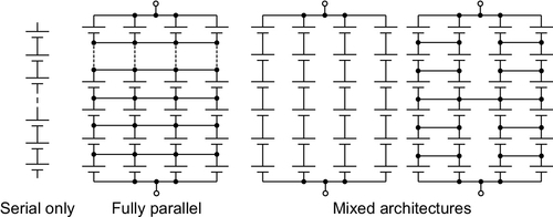
Vehicle batteries feature cells connected in series to provide a sufficient voltage to fulfill the requirements of the electric drivetrain. For optimal energy content with respect to the desired application, it may also be necessary to connect cells in parallel. Various architectures of series-parallel arrangements are possible (see Figure 8.8).
For practical reasons, cells are usually arranged in modules. The battery consists of several interconnected modules and a number of other components (see Figures 8.9 and 8.10):
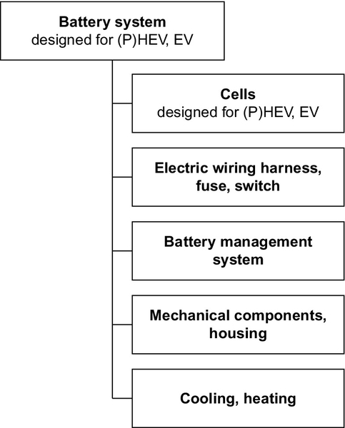
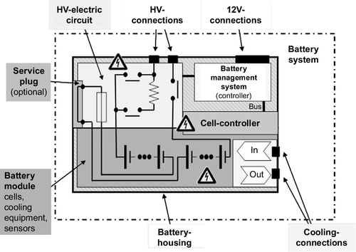
![]() Mechanical components ensure structural integrity;
Mechanical components ensure structural integrity;
![]() Electrical wiring harnesses connect the cells and modules;
Electrical wiring harnesses connect the cells and modules;
![]() Fuses and switches/contactors allow disconnecting the battery from the rest of the high voltage (HV) system;
Fuses and switches/contactors allow disconnecting the battery from the rest of the high voltage (HV) system;
![]() Sensors and electronic control units ensure safe operation and gather information about the current status of cells and battery;
Sensors and electronic control units ensure safe operation and gather information about the current status of cells and battery;
![]() Depending on the actual requirements, heating and/or cooling devices may regulate battery temperature.
Depending on the actual requirements, heating and/or cooling devices may regulate battery temperature.
For safety reasons, the voltage of each individual Li-ion cell needs to be supervised to ensure that the cell stays within the voltage window of safe operation. Thermal management has to be employed to prevent overheating of the battery cells, setting the battery on fire.
Thermal management is also required to ensure battery life. High temperature promotes battery degradation, so thermal losses during operation need to be dissipated from the battery. Especially in high-power (P)HEV applications excess heat must be drained off by an active cooling system. Various cooling media (e.g., air, liquids, refrigerants) are in use.
Reduced power capability of Li-ion batteries at low temperatures is an issue primarily for pure EVs. While (P)HEVs can be operated with the combustion engine if battery power is insufficient for electric driving, reduced low-temperature performance may limit the usability of EVs in ordinary cold-temperature driving. Especially for EVs, integration of a battery heating system may improve vehicle performance.
Since current, especially during charging, has to be adapted to the battery temperature for reasons of safety and durability, the battery management system determines the tolerable charge current based on the battery temperature and provides the information to the external charging unit.
The battery management unit communicates and interacts with other control units in the vehicle, providing necessary information and ensuring proper reaction of the battery on the drivers commands.
8.4 Environmental aspects
8.4.1 Environmental service life aspects
Various environmental issues have to be considered in Li-ion battery design for vehicle applications. Li-ion cells always contain substances that are hazardous to the environment. These substances include carcinogenic transition metal oxides in the positive electrode, LiPF6 and other fluoro-salts, and organic solvents in the electrolyte. Other hazardous compounds may be formed during battery operation. In the event of an accident, the battery may be exposed to abuse conditions such as deformation of the casing, short circuit, and even fire. Under such circumstances, large numbers of potentially hazardous compounds can be formed, polluting the environment and endangering passengers.
In battery and in xEV design, reasonable measures have to be taken to prevent events that result in pollution. At the lowest level, cell chemistry and cell design must be fault tolerant. Failure and abuse conditions that cannot be dealt with at the cell level must be contained at the battery level. At the vehicle level, the battery pack must be protected from mechanical, electrical, and thermal overstresses to prevent conditions where hazardous substances may be released into the environment, and also into the passenger cabin.
In addition, of course, it must be ensured that no polluting agents, such as plasticizers, monomers and oligomers, or organic solvents are released from plastic parts and glues and from electric and electronic devices comprised in the battery.
Throughout the vehicle life, the total amount of pollutants released from the battery in normal operation is usually rather low. This holds true even in the consideration of release in case of accidents, as these events are infrequent compared to the total number of xEVs. When scrapping used-up batteries, though, measures have to be taken to prevent any release of contained substances into the environment.
8.4.2 Disposal and recycling
When a battery is taken out of service, either because the vehicle is scrapped or because the battery has reached the end of its useful life in the dedicated application, batteries should be removed from the vehicle and recycled. In European Union (EU), the battery manufacturer is obliged by the “Battery Directive” (DIRECTIVE 2006/66/EC, 2006) to accept the return of the battery and to dispose of it adequately.
The amount of valuable materials in the battery makes recycling an attractive option depending on raw material prices. Recyclable materials include aluminum, copper, transition metals (Ni, Co) from the cathode active material, and lithium. If the battery is disassembled during the recycling process, printed circuit boards from electronic components may also be recycled, yielding gold and silicon.
It should be mentioned, though, that even if a battery has reached the end of its useful life in the vehicle, the battery cells still retain up to 80% of their initial energy storage capability. This may be sufficient for other applications, such as stationary energy storage systems. Batteries might be used as complete packs in a secondary application, or the batteries may be disassembled and the cells or modules reassembled in a storage system designed for the dedicated application.
8.5 Safety requirements
Different legal requirements exist for Li-ion batteries used in EVs. These are regulations for the transportation of Li-ion cells (e.g., UN38.3; ST/SG/AC.10/11/Rev.5, 2009) as well as safety requirements (e.g., QC/T-743-2006, Doughty and Crafts, 2006).
These requirements are applied to the component level of the battery, cell module, or cell whereas the component generally does not show any leakage, fire, or explosion.
In an EV it has to be assured that no harm can be done to any persons through high currents and voltages. Especially when designed for large-scale production, no compromises whatsoever can be made in terms of safety.
Therefore, when choosing the battery technology and notably the special chemistry of the cells, very close attention has to be paid to the suitability of the technology for an intrinsically safe battery system.
The main transportation and safety tests are listed below:
– Forced discharge: A fully charged cell is discharge to 0 V with 1/3 C.
– Overcharge: Charging a cell with 1 C to a cell voltage of 5 V or for 1.5 h. The cell does not show an explosion, fire, or leakage.
– External short circuit: An external short circuit with R ≤ 0.005 Ω to a fully charged cell is applied for 600 s. Also, if the cell module is exposed to an external short circuit at a temperature of 55 ± 2 °C on the outer housing with R ≤ 0.1 Ω, until the cell module has reached a temperature of 55 ± 2 °C on the outer housing again or after 1 h, no leakage, no opening, no disassembly, no crack of the cell module, no higher temperature than 170 °C on the outer housing of the cell module, and no fire (thermal event) may occur within the test duration and additional 6 h.
– Thermal test: The battery is stored at a temperature of 80 ± 2 °C for maximum. 1 h. During this time, maximum Hazard Level 2 (no leakage; no venting, fire, or flame; no rupture; no explosion; no exothermic reaction or thermal runaway; no irreversible damage to cell). If repair is needed, it is achieved in accordance with FreedomCAR.
Also as requested, with the test article fully charged, increase the temperature in increments of 5 °C (hold time at each temperature step: 30 min) until a thermal effect is detected twice, or the temperature reaches 200 °C above the operating temperature of the cell, or a catastrophic event (e.g., venting or major damage to the device) occurs. The test at 150 °C, 30 min, and 100% state-of-charge (SoC) has to pass at least Hazard Level 4 (no fire or flame; no rupture; no explosion; weight loss ≥ 50% of electrolyte weight).
– Altitude simulation: If the cell module is exposed to an ambient pressure of 11.6 × 10³ Pa for at least 6 h at a temperature of 20 ± 5 °C, thereby no leakage, no opening, no disassembly, no crack of the cell module, no open-circuit voltage less than 90% of its voltage immediately prior to this procedure (if the cell module is not fully discharged), and no fire (thermal event) of the cell module may occur.
– Vibration: For example, for all cells or cell modules with a gross mass of less or equal 12 kg the following is valid:
![]() The vibration shall be a sinusoidal waveform with a logarithmic sweep between 7 and 200 Hz and back to 7 Hz traversed in 900 s;
The vibration shall be a sinusoidal waveform with a logarithmic sweep between 7 and 200 Hz and back to 7 Hz traversed in 900 s;
![]() This cycle shall be repeated 12 times for a total of 3 h for each direction of the vehicle coordinate system;
This cycle shall be repeated 12 times for a total of 3 h for each direction of the vehicle coordinate system;
![]() The logarithmic frequency sweep must meet the following: from 7 Hz a peak acceleration of 1 g is maintained until 18 Hz is reached. The amplitude is then maintained at 0.8 mm (1.6 mm total excursion) and the frequency increased until a peak acceleration of 8 g occurs (approximately 50 Hz). A peak acceleration of 8 g is then maintained until the frequency is increased to 200 Hz.
The logarithmic frequency sweep must meet the following: from 7 Hz a peak acceleration of 1 g is maintained until 18 Hz is reached. The amplitude is then maintained at 0.8 mm (1.6 mm total excursion) and the frequency increased until a peak acceleration of 8 g occurs (approximately 50 Hz). A peak acceleration of 8 g is then maintained until the frequency is increased to 200 Hz.
– Crush test: The tested device should be crushed between a resistance and a crush plate with a force of at least 100 kN, but not exceeding 105 kN with an onset time less than 3 min and a hold time of at least 100 ms but not exceeding 10 s.
The test should end with an observation period of 1 h at the ambient temperature conditions of the test environment.
– Nail penetration test: Penetrate the cell with a steel (conductive) pointed rod through the cell. The rate of penetration should be 8 cm/s or less. The diameter of the rod is 3 mm. The orientation of the penetration should be perpendicular to the electrode plates.
In additional to the aforementioned legal and transportation tests for safety, environmental tests are also required, for example, chemical resistance, noxious gas, and salt spray tests.
8.6 Future developments in cell chemistries
8.6.1 Cathode material trends
To increase the energy density, 5 V materials or materials with higher specific capacities are discussed for future EV applications:
![]() Li-rich oxides,
Li-rich oxides,
![]() LiMnPO4,
LiMnPO4,
![]() LiCoPO4,
LiCoPO4,
![]() HV spinel LiNi0.5Mn1.5O4 (Santhanam and Rambabu, 2010).
HV spinel LiNi0.5Mn1.5O4 (Santhanam and Rambabu, 2010).
HV spinels LiNi0.5Mn1.5O4 show theoretical specific capacities of 146 mAh/g, which is lower than today's used LNMC materials. The advantage of this spinel is the operating voltage in the range of 4.5–4.7 V, which results in increased energy densities on a battery level. Olivine-structured materials such as LiMnPO4 or LiCoPO4 also operate at higher voltage plateaus of approximately 4.5 V and thus also offer higher energy densities. For these HV cathode materials, one major challenge will be the development of electrolyte formulation, which are stable in the voltage-operating range up to 5 V.
Promising cathode materials such as Ni-rich LNMC or Li-rich oxides show increased specific capacities of up to 200 mAh/g in comparison to 160 mAh/g for currently used LNMC. Ni-rich LNMC has the disadvantage of safety behavior. The poor cycling stability still has to be improved for Li-rich oxides (see Table 8.3).
Table 8.3
Comparison of cathode materials
| Cathode | Typical voltage versus lithium | Specific capacity (mAh/g) | Specific energy (Wh/kg) | Cycle stability | Calendar life | Intrinsic safety | Cost |
| LFP | 3.4 | 155 | 530 | +++ | ++ | +++ | ++ |
| LMO | 3.9 | 115 | 470 | + | − | ++ | +++ |
| NMC | 3.8 | 155 | 590 | ++ | ++ | + | + |
| NCA | 3.7 | 175 | 650 | ++ | ++ | − | − |
| hNi-NMC | 3.7–3.8 | 180–200 | 710 | + | + | − | + |
| OLO | 3.6 | 240 | 860 | + | + | + | + |
| HV spinel | 4.7 | 135 | 630 | + | + | ++ | ++ |

8.6.2 Anode material trends
Most promising future anode materials are alloyed anodes with silicon or tin. Li–Si with about 4000 mAh/g and Li–Sn with about 990 mAh/g show specific capacities that greatly exceed that of graphite with 372 mAh/g. Still the problem of the large volume expansion of these alloy materials during charge and discharge has to be solved. Here the main trend is the use of a mixture of alloy with carbon or graphite in combination of nano-sized materials to suppress the mechanical stress of the volume expansion–contraction.
Table 8.4 gives an overview of the characteristics of the different potential anode materials for automotive applications.
Table 8.4
Comparison of anode materials
| Anode | Rate capability | Typical voltage versus lithium | Reversible specific capacity (mAh/g) | Specific energy (Wh/kg) | Cycle stability | Calendar life | Intrinsic safety | Volume expansion | Cost |
| Natural graphite | + | 0.1 | 350–360 | ++ | + | − | + | − | ++ |
| Artificial graphite | ++ | 0.1 | 340–350 | ++ | ++ | + | ++ | – | + |
| Hard carbon | +++ | 0.6 | > 300 | ++ | ++ | ++ | ++ | + | + |
| Soft carbon | ++ | 0.6 | 250–320 | + | ++ | ++ | ++ | + | ++ |
| LTO | +++ | 1.5 | 160 | − − − | +++ | +++ | +++ | +++ | + |
| Si–C | +/++ | 0.2 | > 400 | +++ | − | −− | − | − | + |

Also a future trend, except for anode and cathode materials, is expected with the development of safer (nonflammable) electrolyte systems such as polymer or even solid electrolytes.
8.7 Future developments in Li-ion battery packs
Future trends in battery requirements are primarily associated with higher customer value and lower cost. Driven by cell development and customer demand, the electric-driving range of EVs will improve significantly. Energy density will increase while maintaining battery weight and volume. Because of the effects of volume and downsizing, battery costs will also decrease.
For PHEVs, the average electric-driving range will probably settle between 35 and 50 km, sufficient for the majority of a vehicle's journeys in urban usage. Cell development beyond that range will be used for downsizing the battery pack, reducing its price, and making PHEV attractive for a larger number of customers. It already seems that PHEVs are pushing into the HEV market, offering a better customer value and reducing HEVs to special applications and niche markets in the future.
Standardization of battery components (beyond the Li-ion cells, see below) is presently being promoted throughout the industry, to the benefit of the (sub)component supplier, the battery pack designer, and the manufacturer. Electric/electronic components such as the battery management system, as well as contactors and switches, fuses, and current sensors are discussed for standardization.
Today the choice of electric and electronic components for automotive HV applications is still small. Because the market is just starting to grow, many components that are in use in other industrial HV applications (e.g., contactors, plugs, current sensors) are not yet qualified for automotive applications. First components are available on the market, and more are under development and qualification. This will allow a greater degree of freedom in future battery design and manufacturing, allowing higher currents and voltages in the vehicle.
Integration of various electronic functionalities in one controller board or even on-chip is already in progress and will result in smaller battery management systems and a higher energy and power density on a battery-pack level.
Another field in which improvements can be expected is the thermal management of battery packs. Most of the cooling concepts used today come with a drawback. Liquid cooling requires pumps and compensating reservoirs in the vehicle, and—depending on the required cooling power—expensive heat exchangers. Air cooling is rather cheap and lightweight, but takes precious space for in- and outlet tubings. If fed from the passenger cabin, noise of the fans might be an issue, too.
Today it seems that the technically most elegant solution for battery heat dissipation is direct refrigerant cooling. It is technically most challenging with respect to temperature homogeneity and thermal management but offers significant advantages in weight, volume, and cost. For future high-power applications in HEVs and PHEVs it will probably become the market standard. In EVs, on the other hand, where power density is much smaller, passive heat dissipation might be an option, especially with larger batteries and increased driving ranges.
Cell development, standardization, downsizing, and increasing customer expectations might make it necessary to use parallel battery architectures that bring in additional challenges for safety, both for the intrinsic safety of the cell, as for safety devices and mechanisms in the battery pack.
8.8 Market forces and future trends
To minimize the costs for an automotive battery, a high degree of standardization of the battery components is necessary. The definition of a standard for automotive battery cells (standardized prismatic, pouch, and cylindrical cells) within the VDA (the German Association of the Automotive Industry) certainly was a milestone for automotive batteries in terms of cost and industrialization (DIN SPEC 91252). Other battery components such as battery management systems, fuses, and plugs are also in discussion for standardization.
Standardization also means implementation of a sustainable modular approach for future battery concepts. A modular approach comprises the development of cell modules based on standardized cell formats, which can be used in a wide range of applications (HEV, PHEV, and EV). These cell modules are independent of the cell chemistry used and further developments regarding increase of energy and power density on cell level.
Battery technology for traction applications is a field that evolves quickly. Despite long development cycles, significant improvements can be foreseen for the next decades. For automotive applications such as traction batteries, various directions are followed for the different applications in HEV, PHEV, and EV. A summary of technical development targets is given in Table 8.5.
Table 8.5
Development targets for xEV batteries
| HEV | PHEV | EV | |
| Increase energy content | 0 | + | ++ |
| Increase power | ++ | + | + |
| Reduce size | + | ++ | 0 |
| Reduce weight | 0 | + | ++ |
| Increase durability | 0 | + | + |
| Increase usability | 0 | + | + |
| Maintain safety | ++ | ++ | ++ |
| Energy density | 0 | + | ++ |
| Power density | ++ | 0 | + |
| Life cycle | ++ | + | 0 |
| Calendar life | 0 | + | + |
| Low-temperature performance | 0 | + | + |
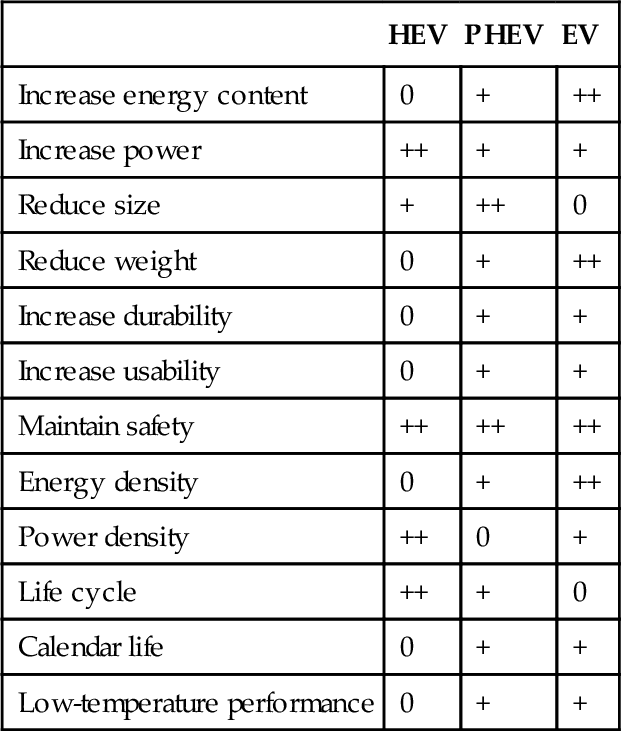
++, very important; +, important; 0, less important.
8.9 Summary
Li-ion batteries support other technologies for automotive traction applications. Energy and power density, safety and durability, and of course costs are crucial characteristics for the batteries to have wide acceptance in the market.
Most important trends for future development are as follows:
![]() Further standardization on cell and battery pack components;
Further standardization on cell and battery pack components;
![]() High capacity anode/cathode materials;
High capacity anode/cathode materials;
![]() HV cathode materials;
HV cathode materials;
![]() Lightweight construction of battery packs;
Lightweight construction of battery packs;
![]() Cost reduction on battery system design (cooling, electronic architecture).
Cost reduction on battery system design (cooling, electronic architecture).