
Thermal management of batteries for electric vehicles
C. Huber1; R. Kuhn2 1 Institute for Electrical Energy Storage Technology, Munich, Germany
2 TUM CREATE Ltd, Singapore
Abstract
Temperature and humidity level highly affect the performance, safety, and lifetime of battery cells, thus making their control a key challenge for battery integration into vehicles. Depending on cell type and intended application, a variety of thermal management systems is existent, complicating the selection and the dimensioning process. Due to a wider market penetration and a trend toward high-capacity battery packs and fast charging, thermal management will significantly gain further importance for the overall vehicle concept.
13.1 Introduction
As are virtually all electrochemical systems, battery characteristics and behavior are highly dependent on the battery’s thermal operating conditions. Temperature level, profile, and uniformity have a significant impact on the electrochemical reactions and therefore on the performance, safety, and lifespan of battery systems. To be successful in an automotive environment, reliability and longevity are key factors. Further studies show that for a broad adaption of electrified vehicles, they have to be as easy in handling as conventional cars. Evidentially, most customers are not willing to study the singularities of battery systems, but rather expect a vehicle that is fully operational under all conditions (NPC, 2013). A sophisticated battery thermal management system is therefore an essential requirement.
The following chapter briefly describes the basic temperature-related effects and thermal characteristics of automotive battery cells before highlighting the design process of a holisitc thermal management system. All relevant system approaches are introduced and an overview on their characteristics, advantages, and disadvantages is given. Dimensioning and peculiarities of the individual system topologies are compared in detailed exemplary design calculations. The section is concluded by an outlook on future developments and a collection of recommended further readings.
13.2 Motivation for battery thermal management
13.2.1 Temperature effect on cell performance and aging
A relation between kinetic reaction rate and temperature is given by the Arrhenius equation. For most battery applications it implies that already a temperature rise by 10 K doubles the speed of internal reactions, including unwanted aging and self-discharge processes. Hence, temperature is to be considered as the most important factor influencing cell performance and cell aging. To achieve a cycle or calendar life demanded for automotive application (10 years and/or 1000 cycles at 80% DoD) a closer look at thermal management and its impact on battery life is essential.
As due to its high specific energy density and cycle stability, lithium-ion technology has emerged to be the most promising technology in automotive applications for the next years (Anon, 2010), the following considerations focus on this cell chemistry, giving brief information on other cell-types where appropriate.
13.2.2 Capacity and power fade as a function of temperature
Chemical and mechanical processes at the different cell components can lead to irreversible aging effects. Besides the dissolution of active material into the electrolyte and the electrolytes oxidation, the degradation phenomena at the negative electrode are considered to have the highest impact (Aurbach et al., 2002; Kassem et al., 2012).
On the anode side of lithium-ion batteries, aging is significantly influenced by the development of a solid electrolyte interphase (SEI) over time. A growing SEI results in a loss of continuous lithium-ions and a decomposition of the electrolyte (Methekar et al., 2011). High temperatures may lead to a dissolving or breaking up of the SEI and generation of lithium salts, which are less permeable to the lithium ions and increase the electrode’s impedance (Koltypin et al., 2007). As a consequence, further lithium is bound to form a new SEI layer.
Once active material has been irrevocably transformed into passive phases, usable energy capacity is permanently reduced. Rate and velocity of most of these destructive processes highly depend on electrode/electrolyte couplings but virtually always also are a function of ambient temperature. Elevated temperatures have been widely proven to speed up secondary reactions and cyclable lithium loss (Ho et al., 2002; Ramasamy et al., 2005).
The same is true for the power fade and the rise in internal resistance over time (Zhang and White, 2007). Detailed effects of temperature impact on battery aging is still subject to intensive research; a more detailed overview on the single effects is given in Broussely et al. (2005) and Vetter et al. (2005).
13.2.3 Self-discharge
In addition to the irreversible mechanisms of capacity and power fade, charged batteries also lose their stored energy content because of a reversible self-discharge. The process is primarily driven by uncontrolled reaction at the SEI-electrolyte boundary layer and therefore also accelerated by elevated temperature and state of charge (Utsunomiya et al., 2011).
Figure 13.1 illustrates self-discharge and irreversible capacity fade over time for a lithium-ion cell at different temperature levels (Jossen and Weydanz, 2006).

Another very detailed review of recent research on thermal impact on aging and self-discharge mechanisms is given by Bandhauer et al. (2011).
In addition to the aforementioned aging processes that go along with cycle—but also with calendar life—temperature level also has an impact on the cell’s active charging and discharging characteristics.
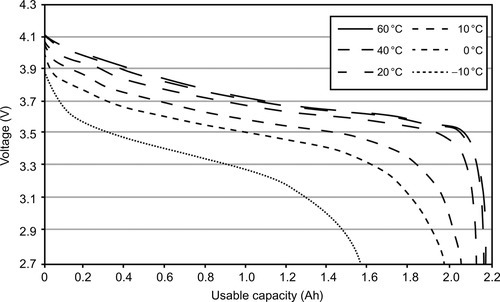
One remarkable effect results from the internal resistance of the cell materials being a function of temperature. Although the specific resistance of the electrolyte decreases with elevated temperature, the ohmic resistance of the metal conductors increases. In its entirety the effect of the electrolyte is the determining factor, so that for almost all cell types, the overall-resistance decreases with rising temperature, which then leads to an elevated performance in terms of usable capacity and power (see Figure 13.2). Amount of usable capacity in this context is defined, as the amount of energy retrievable between the maximum and minimum operating voltages of a cell defined by its manufacturer.
13.2.4 Thermal properties of selected battery types
Battery response to ambient temperature conditions and internal heat generation is highly dependent on the cells’ thermal material properties, namely the specific heat capacity and thermal conductivity. Knowledge about these values is absolutely necessary for designing an efficient thermal management system, although the information is not easy to get. Exact values for specific cells are highly dependent on form factor, casing material, and thickness. They can be either calculated from their single components and their respective mass fraction or determined experimentally.
Common empirical methods include the accelerated rate calorimetry, the Xenon Flash method (Maleki et al., 1999), insertion of thermocouples within the cell (Forgez et al., 2010), or the novel thermal impedance spectroscopy approach (Barsoukov et al., 2002). Although figures differ between single cells, a rough estimation of selected common battery types is given in Table 13.1.
Table 13.1
Estimated thermal properties of selected cell types
| NiCd | NiMH | Li-ion | Li-ion polymer | ||
| Spec. heat capacity | (J/kg K) | 1250 | 521–787 | 960–1040 | 1180 |
| Thermal conductivity (through plane) | (W/m K) | 0.87–1.26 | 0.74 (Yazdanpour et al., 2013) | 0.34–1.09 | 0.32–0.89 |
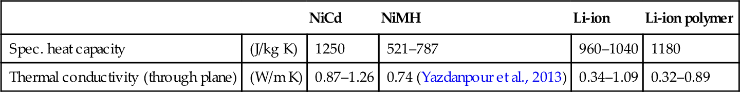
Falk and Salkind (1969), Brooman and McCallum (1971), Pesaran and Keyser (2001), Yazdanpour et al. (2013), Maleki et al. (1999), and Fleckenstein et al. (2011).
When interpreting these properties and their impact on the system level, it’s fundamental that these are given mostly as specific values. A large and heavy battery pack (e.g., as used in BEVs) consequently acts more inertial toward temperature changes as a smaller and lighter pack (as it is used in PHEVs). Hence, risk of overheating can be higher for smaller packs. Another point affecting the system behavior is that depending on cell size, geometry, and thermal conductivity the temperature at the core might significantly differ from the one measured at the cell surface. Sensing hardware and control mechanisms have to compensate for this, making sure that even the local temperature maximum is still kept within a safe temperature range. Recommended safe operating temperatures and upper or lower limits for different cell types are given in Table 13.2 (Jossen and Weydanz, 2006). (Values describe the highest or lowest surface temperature.)
Table 13.2
Operation temperature and limits of selected cell types
| Lead-acid | Ni-MH | Li-ion | Li-ion polymer | |
| Charging | ||||
| Recommended T (°C) | 5–25 | 15–30 | 20–30 | 18–25 |
| Min T (°C) | − 20 | 0 | 0 | 0 |
| Max T (°C) | 50 | 45 | 45 | 60 |
| Discharging | ||||
| Recommended T (°C) | 0–30 | 15–30 | 20–30 | 18–25 |
| Min T (°C) | − 20 | − 20 | − 20 | 0 |
| Max T (°C) | 50 | 65 | 60 | 60 |

For most lithium-ion battery packs with gel-based or liquid electrolytes, the absolute minimum temperature is defined by the electrolyte’s freezing point, typically at approximately − 30 °C. For specific use cases, cells can be equipped with custom electrolytes to further widen the operation range at the cost of other drawbacks (Behl and Edward, 1998).
On the other side of the scale, maximum storage and operating temperature has to keep a safe margin from the threshold at which uncontrolled exothermic heat generation starts, which can lead to an irreversible and uncontrolled destructive process called thermal runaway. This process is widely described as a three-staged process that can begin as early as at around 80–90 °C (Spotnitz and Franklin, 2002; Rao and Wang, 2011).
13.3 Heat sources, sinks, and thermal balance
To predict the actual cell temperature rise for a given load scenario, a simplified heat balance between the cell and its surroundings can be compiled. Therefore all relevant heat sources and sinks have to be considered. For safely preventing any overheating in operation, the heat generation rate of the selected cells has to be reliably known in detail.
13.3.1 Heat sources
The heat generated from the battery originates from several effects, including the Joule’s heat from the ohmic internal resistance and from polarization overpotential, as well as from reversible heat effects. Except for very small currents (< C/5), the cell current is the most influential operation variable for heat release of a given cell. Temperature rise for similar pouch cells under an identical ambient temperature of 25 °C but varying discharge C-rates are shown in Figure 13.3.

As the absolute amount of heat released also is dependent on a cell’s state of health and even can fluctuate between identical cells due to manufacturing variations, the safest method is to measure the heatflux for the predicted current profile and add safety margins.
The magnitude of occurring currents highly depends on the type of the traction battery and on the cell connection scheme. Typically HEVs face higher currents at short peak loads, whereas PHEV and BEV battery packs normally see lower currents but higher used capacity (Omar et al., 2012). Another factor of significant influence is the planned charging method. With upcoming fast-charging battery packs, the recharging increasingly gets the most influential operation mode. Characteristic values according to the U.S. FreedomCAR norm are given in Table 13.3.
Table 13.3
Requirements for different electric vehicle types according to USABC and Freedom CAR
| HEV | PHEV | BEV | ||
| Typical chemistries | NiMH/Li-ion | Li-ion | Li-ion | |
| Total energy storage capacity | kW h | 1–2 | 5–12 | 22–80 |
| Actually used capacity | % | Max. 40 | 75 | 80 |
| Discharging | ||||
| Peak power (10 s pulse) | kW | 25 | 38–50 | 80–310 |
| Regeneration | ||||
| Peak power (10 s pulse) | kW | 35 | 25–30 | 40–155 |
| Recharging | ||||
| Recharge power | kW | n/a | 1–2.8 | 5–135 |
| Temperature | ||||
| Operating range | °C | − 30 to 52 | − 30 to 52 | − 40 to 50 |
| Unassisted survival range | °C | − 45 to 60 | − 45 to 60 | − 45 to 60 |
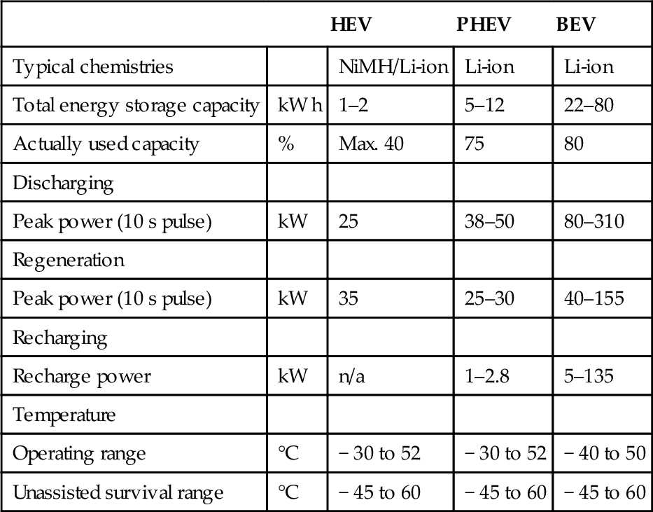
FreedomCAR (2013) and Young et al. (2012).
13.3.2 Heat transfer
Heat transfer between the cell and its surrounding is primarily driven by the three main mechanisms of thermal transport: radiative, convective, and conductive processes.
13.3.2.1 Radiation
The amount of heat dissipated by radiation can be estimated from the Stefan-Boltzmann equation (Equation (13.1)) and is determined by the temperature difference to the environment as well as the surface area A and the emission coefficient ε. Besides the external impact, radiation within the battery pack or between battery pack and vehicle also can have an impact.
13.3.2.2 Convection
Most of the commercial battery thermal management systems rely on convection as controllable heat dissipation methods. Depending on whether the surrounding media is actively driven or not, the mechanisms is called forced or natural convection. The cooling or heating effect can be realized using gaseous or liquid media (e.g., air or water). The basic correlations for conductive heat transfer are given in Equation (13.2). Hereby ![]() labels the average convection coefficient, being a function of the Nusselt, Reynolds, and Prandtl number of the flow field (Incropera et al., 2011).
labels the average convection coefficient, being a function of the Nusselt, Reynolds, and Prandtl number of the flow field (Incropera et al., 2011).
The actual amount of heat transferable via convection depends on the temperature difference, the heat capacity of the media, the flow velocity, media viscosity, the contact area A, and many factors more. In general, one can distinguish laminar and turbulent flow with the turbulent one being the more effective one, due to the smaller boundary layer between solid and fluid. For basic geometries values can be estimated from empirical formulas. Calculation of complex geometries is highly nontrivial and can require extensive computational fluid dynamic simulations (Verein Deutscher Ingenieure, 2005).
13.3.2.3 Conduction
As within all battery packs the single cells are somehow linked to a mechanical casing and connected by current collectors, there’s also some thermal flux via conduction. Although during standard operation it plays an inferior role, for extreme ambient conditions (e.g., cold winter operation) this fraction can have an impact.

Conductive heat flux given in Equation (13.3) can be minimized by using insulating material layers (small λ/large d) or reducing the areas being in direct contact with the hot and cold environment (A).
For safety reasons also the cell-to-cell conduction should be considered. As cells are in close contact and connected by metal busbars, a thermal runaway of one cell could propagate throughout the whole pack and cause even more fatal consequences. This risk can be mitigated by constructive measures, such as insulating layers between the single cells or thermal fuses.
13.3.3 Thermal balance
Summation of all heat sources and sinks in equilibrium leads to a balance of heat fluxes according to Equation (13.4), wherein the single ![]() refers to the battery heat generation and the three dissipation fluxes mentioned before. Heat fluxes from the battery to the surrounding area are defined as positive, heat fluxes from the ambient to the battery are considered negative.
refers to the battery heat generation and the three dissipation fluxes mentioned before. Heat fluxes from the battery to the surrounding area are defined as positive, heat fluxes from the ambient to the battery are considered negative.
In case there is additional heat released within the cell (e.g., due to an increase in current), the temperature of the cell rises. As all of the heat sink mechanisms scale with the temperature difference toward the ambience, also the dissipating heat flux will increase. In parallel, the internal resistance of the cell decreases due to the higher temperature resulting in a slower temperature rise. Over time this will cause a new equilibrium condition with stable temperatures.
If the internally generated heat cannot be dissipated adequately (e.g., due to an internal heat accumulation), rising temperatures can lead to deleterious reactions, such as irreversible aging, or even culminate in a fatal thermal runaway.
13.4 Design aspects of thermal management systems
A sophisticated thermal management system is therefore a requirement for keeping the battery system operating within its most healthy, efficient, and safe temperature range. Besides that it also helps to ensure that all individual cells are operated in a roughly similar environment and therefore show uniform operating and aging behavior. As for serial cells interconnected in a pack, the overall-performance always is determined by the weakest cell; it’s highly desirable to minimize the temperature spread. Recent studies have shown that a variance of well less than 5 K throughout the whole battery pack is essential for real-life application. Further, also within the single cells, a uniform temperature distribution is to be achieved to reduce current density and state of charge inhomogeneities (Fleckenstein et al., 2011).
The main tasks of a battery thermal management system therefore can be summarized as the following:
![]() Minimizing the impact of hot or cold external ambient conditions on the battery pack.
Minimizing the impact of hot or cold external ambient conditions on the battery pack.
![]() Minimizing the temperature spread between and within the single cells.
Minimizing the temperature spread between and within the single cells.
![]() Safely preventing hazard of uncontrolled cell temperatures and cell-to-cell propagation of thermal runaway.
Safely preventing hazard of uncontrolled cell temperatures and cell-to-cell propagation of thermal runaway.
![]() Safely preventing any condensation within the battery pack and actively controlling humidity.
Safely preventing any condensation within the battery pack and actively controlling humidity.
The term thermal management in the following is used for all structural measures, material selection, and operational strategies aiming at these goals. The following chapter introduces all relevant system topologies and gives an idea of their typical application fields. The exemplary design calculations for different systems are then presented, highlighting the impact of the choices.
13.4.1 Design process
As with all complex technical systems, defining an automotive battery thermal management system is always a compromise between rivaling goals, especially weight and cost targets. As the issue is also highly linked to different disciplines and other components of the vehicle, a detailed screening of requirements and boundary conditions is indispensable. Tasks and activities within the battery thermal management are highly linked to the battery management system and the vehicle energy management. Although all safety-relevant processes have to be realized by an encapsulated and redundant system, optimization tasks or comfort functions can be outsourced to the central vehicle controller. Despite all the parties involved and the cost pressure, safety of the thermal management is the factor of outmost importance.
Within the following section all the relevant steps toward designing a thermal management system for a lithium-ion-based BEV battery pack are highlighted.
One of the first steps when designing such a system is identifying and recording all requirements arising from the overall vehicle’s type, design, and the environment in which it is to be operated. Regarding the ambient conditions it is necessary to consider the extreme values and add safety margins in both directions. Typical automotive operational requirements are aligned with global climate extremes and normalized in DIN 1946-2: 2006-07 (Anon, n.d.). Accordingly, relevant temperature range for a universal vehicle aimed for global operation spans as wide as from − 45 °C up to 55 °C and might be narrowed for regional adapted vehicles only (Großmann, 2012). In case of a localized approach it can now also be derived, whether the thermal management system has to comprise both heating and cooling or can be reduced to one of the tasks. Additional requirements arising from special use scenarios (e.g., durability for abrupt temperature changes, high humidity, or even watertightness for offroad use) must be regarded from the start.
As discussed at the beginning of the chapter, different cell chemistries have slightly different operational temperature windows. Hence the battery type and the typical ambient conditions give early evidence of the expected complexity of the climatization task.
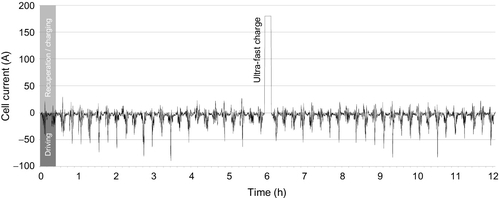
To further break down the system’s dimensioning, the most demanding working points must be identified from the vehicle’s load profile. The resulting energy demand can then be overlayed with the crucial ambient condition to define the maximum load design point. Besides this criteria for determining for the absolute dimensioning, the minimum load and optimum load points also have to be defined.
Figure 13.4 shows an exemplary load profile for a fast-charging BEV in urban traffic. The current curve is characterized by significantly fluctuating load levels and by very distinctive peaks during acceleration and fast charging. Negative current values are those discharging the cell, and positive values identify recuperation and charging. Within this example, the very high currents of up to 180 A during fast charging mark the most challenging loadcase and can therefore be interpreted as the crucial design point for the cooling system.
Once all battery-related key criteria is defined, in a final step all requirements and limitations arising from the vehicle’s package must be considered. Besides amount and position of available space and weight restrictions, the location of the battery modules plays an important role. For some packages, batteries are foreseen at several different locations within the car, further complicating the layout of the thermal management system. Especially for smaller vehicles, the available power for auxiliary systems and economic considerations can be determining for the design process.
Based on the list of requirements and boundary conditions, a basic topology can now be chosen from a variety of possible solutions. Typically, they are classified based on the used cooling media, the interface toward the cells, and their integration into the vehicle’s overall thermal management system. In the following information, all relevant systems are covered in detail including their specific characteristics. The section is concluded by a summarizing comparison of the technologies and an evaluation of their eligibility for distinctive use cases.
13.4.2 Air-cooled systems
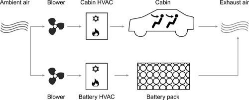
Air-cooled systems rely on ambient air as a medium and offer a relatively simple design that results in low costs for production and maintenance. They can be realized in a way that solely uses outside air or in a topology that benefits from the already preconditioned cabin air. In certain scenarios cooling requirements for cabin and battery might differ, there’s also a third version that uses a second evaporator solely for the battery to condition the cooling air.
All three concepts are already present in commercial vehicles, as the Nissan Leaf or the Toyota Prius, and are shown in Figures 13.5–13.7.
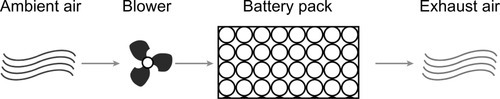

As there is no need for isolation between coolant media and batteries, those systems can be easily adapted to a variety of cell form factors. The absence of liquid cooling media also significantly simplifies the realization of battery-swapping systems, as there are no issues with leak tightness and liquid connectors.
Due to the air’s small heat capacity, however, challenging cooling tasks require a high mass flux resulting in voluminous ducts and manifolds, and additional filters are required to prevent debris from entering the battery pack (Brotz et al., 2007).
Figure 13.8 illustrates the battery pack of the Toyota Prius air ducts and fans, which account almost for the same volume as the battery itself.
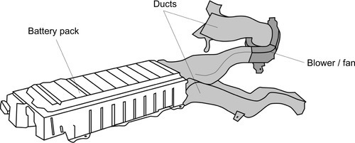
Besides the space requirements, another downside of air-based concepts can be the background noise created by the multiple fans or blowers and the direct link between passenger and battery compartment.
13.4.3 Dielectric liquid-based systems
Another approach also featuring direct contact between coolant and cells, but using liquid media instead of air is based on dielectric fluids. Hereby single cells or the whole battery pack is stored in a fluid environment (e.g., transformer oil). Temperature moderation is achieved by natural and/or forced convection of the fluid and is supported by the media’s very high specific heat. Although cooling efficiency is good and the dielectric fluid adds safety to the concept, the relatively heavy weight and the difficult handling during assembly and maintenance has prevented the dielectric liquid-based system from being widely used thus far.
13.4.4 Indirect liquid-cooled systems
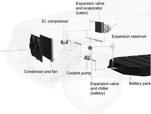
Already present in many existing vehicles for cooling other components, an indirect liquid cooling system can also be used to control battery temperature. In this system a liquid coolant is circulated between the battery pack and a heat sink. The cells are not in direct contact with the coolant but are linked to the coolant circuit via conductive materials (e.g., aluminum). Depending on ambient temperatures and power requirements the heat sink can be a simple radiator or an evaporator that is integrated into a refrigerant cycle. The most flexible systems combine both circuits and dynamically switch between them using the air cooler for standard operation and the chiller only during peak loads or high ambient temperatures. Such systems are used among others in the Chevrolet Volt and the Tesla Motors’ vehicle range. Common liquid cooled system layouts are depicted in Figures 13.9 and 13.10.

The biggest advantage of liquid cooling is within the significantly higher power due to elevated mass flux and heat capacity, enabling a very compact design. Remarkable power levels and good controllability also qualify these systems for challenging concepts as fast charging or use in extreme climate conditions.
A representative liquid cooling system and the positioning of its components within an actual vehicle are shown in Figure 13.11.
The downside to an indirect liquid-cooled system might be the more complex layout that also results in a higher system weight. Due to the additional components and piping, those systems may also be more error-prone and maintenance-intensive compared to basic air cooling. And on a final note there’s the risk of leakage, which, especially in the event of an accident, can lead to serious consequences (Neumeister et al., 2011).
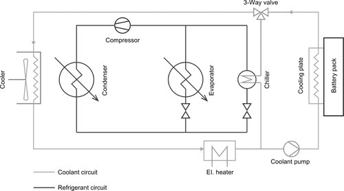
13.4.5 Refrigerant-based systems
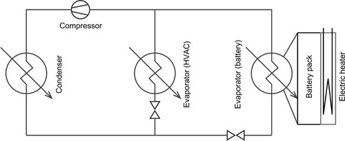
A comparatively new approach tries to overcome the disadvantages of a dual-circuit model by directly integrating the battery cooling into the existing refrigerant cycle. The battery is thermally linked to a direct evaporator plate, which is added to the refrigerant circuit—making unnecessary a separate coolant loop, chillers, and heat exchangers. This construction saves weight and can be even more compact than a conventional liquid system. Because of the well-defined evaporation temperature an even temperature level can be achieved throughout the whole cooling surface, resulting in a very uniform distribution. Unfortunately, joining multiple evaporators into a single refrigerant circuit requires very careful design of the system’s components and complex control. If battery heating is required, an electric heating plate has to be added to the system. The corresponding setup was first introduced in the hybrid model of Mercedes Benz S400 in 2009 and is currently used in several HEV and BEV models as the BMW i3 or the BMW Active Hybrid 7 (Bauchrowitz et al., 2010). A schematic refrigerant circuit design is given in Figure 13.12.
As for the coolant- and the refrigerant-based concepts, the cooling power mostly originates from the vehicle climate compressor; as such, the selection and operation of this component gain significantly in importance. The task of providing sufficient cooling power for the refrigerant cycle transforms from a merely comfort feature to a critical safety requirement, especially for fast-charging BEVs.
Whereas for conventional ICE cars, the compressor is mostly mechanically driven by the traction engine, HEVs and BEVs have to use a hybrid or fully electrical compressor (Jung et al., 2007; Heckenberger, 2007). Decisive factors for the selection include the appropriate voltage level as well as the power rating, being adequate for driving cabin and battery cooling simultaneously. At this point due to the very different load profiles for cabin and battery cooling, a conflict of objectives can arise, each of which has to be considered at an early stage and be mitigated by suitable control strategies. If the distribution of cooling power between the battery and the cabin conflicts, for safety reasons, the battery coolant circuit always has to be prioritized.
Typical representatives for different use cases in HEV, PHEV, and BEV applications are given in Table 13.4.
Table 13.4
Representatives for electric compressors used in HEV, PHEV, and EV applications
| Mitsubishi iMiev (Umezu and Noyama, 2010) | Toyota Prius | BMW 7 active hybrid | |
| Vehicle class | BEV | PHEV | HEV |
| Compressor type | Scroll | Scroll | Scroll |
| Displacement | 30 cm3 | 14 cm3 | 34 cm3 |
| Voltage range | 220–400 V DC | 200–288 V | 120 V |
| Max el. power | 4.5 kW | 3.4 kW | n.a. |
| Refrigerant | R134a | R134a | R134a |
| Max. rev | 6000 rpm | 7500 rpm | n.a. |
| weight | 10.2 kg | 5.5 kg | 6.6 kg |

In general those systems are compatible with all automotive refrigerants as R134a, R744, and R1234yf. But as R134a has been banned by the European Union for new cars and R1234yf is highly flammable, future developments point toward making R744 (CO2) the standard (Parliament and Union, 2006).
Another aspect driving this development is that R744-based systems can also be operated in heat pump mode to warm up the battery pack (Wehner and Ackermann, 2011; Ackermann et al., 2013).
13.4.6 Thermoelectric elements
Because they are already present in the automotive field for other applications (as seat cooling, etc.), thermoelectric elements can also be used in battery thermal management. Especially for low-to moderate-power tasks this approach can be a rewarding alternative to liquid- or air-based systems. The peltier elements are directly or indirectly linked to the battery cells and feature a compact size and moderate weight as well as the total lack of mechanical parts or liquid media. Hence they’re virtually maintenance free and of high longevity. Furthermore, one element can be used for cooling and heating, easily switching between the modes by inverting the supply voltage polarity.
As the Peltier element is one self-contained unit and does not need any connection to other vehicle modules or coolant media, it’s also well suited for battery swapping systems and could be directly integrated into the exchangeable battery pack. Novel approaches focus on application of the elements directly on the module connectors, individually controlling each single cell’s temperature (Kossakovski, n.d.). In theory it would also be possible to use the same Peltier elements as thermal generators to gain electrical energy from a temperature difference.
The main disadvantage of the technology is the poor efficiency of the Peltier process that limits realistic battery pack applications to some 100 W of cooling power.
13.4.7 Phase change material
The idea of using phase change material (PCM) to temporarily store heat energy is well established and is already used for several purposes, mostly in stationary civil and energy engineering. The principle could also help to reduce the cooling efforts for automotive battery packs and to mitigate peak loads, enabling smaller thermal management systems. The key to a successful automotive application is the proper selection of material in terms of transition temperature, high specific heat of fusion, and thermal conductivity.
An overview on common materials with melting points within the battery-relevant temperature range is given in Table 13.5.
Table 13.5
Common phase change materials
| Material | Melting point (°C) | Heat of fusion (kJ/kg) | Thermal conductivity (W/m K) | |
| Solid @ 20 °C | Liquid @ 45 °C | |||
| Organic | ||||
| Paraffines | ||||
| C17H36 | 21.7 | 213 | 0.214 | 0.193 |
| C18H38 | 28.0 | 244 | 0.358 | 0.194 |
| C19H40 | 32.0 | 222 | 0.21 | 0.193 |
| C20H42 | 36.7 | 246 | n.a. | 0.201 |
| C22H46 | 44 | 249 | n.a. | 0.202 |
| Lauric acid | 44 | 177 | n.a. | 0.213 |
| Inorganic | ||||
| LiNO3 | 30 | 296 | 1.37 | 0.58 |
| Water | 0 | 334 | 2.2 @ 0 °C | 0.60 |
| CaCl2 | 30 | 190 | 1.088 | 0.54 |
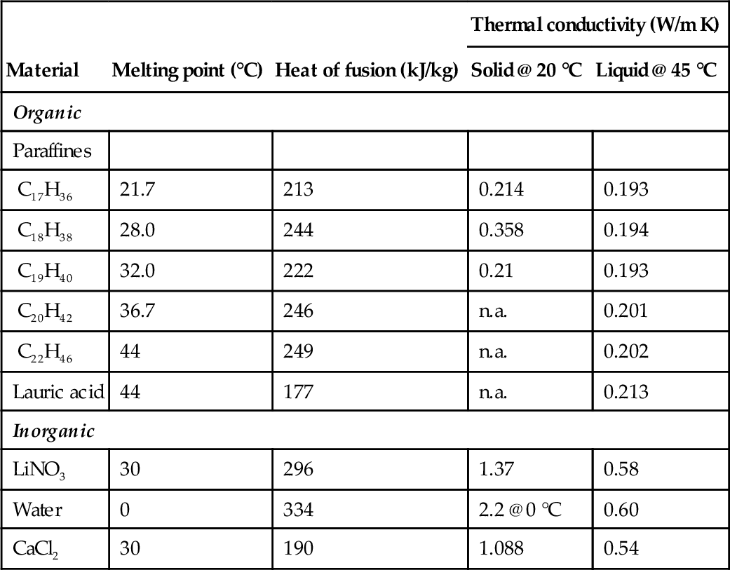
The special requirements of an automotive application narrow the selection of proper material, as the transition temperature should fall within the cell operation temperature and high thermal conductivity is desirable to enable reactive systems capable of mitigating short peaks (e.g., during fast charging).
As these premises cannot be satisfactorily met with the relevant pure materials, a promising approach is to combine multiple materials with their respective properties. This means one highly conductive component acting as structural matrix housing the actual energy storage material. To prevent loss by leakage and to facilitate handling, the material undergoing the phase-change can be microencapsulated. Figure 13.13 illustrates the section view of such a composite material.

The first studies with cylindrical cell battery packs for light electric vehicles have already proven the general suitability of the concept. Some approaches even use the phase change material to hold the cells in place (Kim et al., 2008) whereas other designs make use of heat pipes to thermally link them to the battery cells.
Because of the defined limited heat storage capacity, PCM does not qualify for universal use, but it can be favorable for special use cases and as a supporting element for one of the other cooling systems. The same is valid if the choice of components is limited and cooling requirements have to be met with a selection of existing parts. Due to its total scalability in terms of heat storage capacity and its flexibility in shape and mounting position, the composite PCM material can continuously close the gap between the discrete power levels of other components, enabling a choice for the next smaller version. As this material is economically priced and maintenance free, it can deliver cooling power more cost-effectively when compared to the scale-up of a conventional system.
13.5 Exemplary design calculations
In addition to the general considerations discussed in the previous chapter, the following section gives exemplary design calculations for dimensioning the different thermal management systems. To enable a comparison between the power ratings of the systems, the identical battery module is used as a starting point for all calculations, and external effects as well as auxiliary consumers are neglected.
13.5.1 Reference battery module
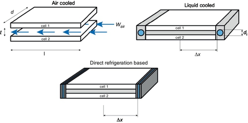
The reference module comprises twelve 60 Ah pouch cells in a 6s2p configuration. Figure 13.14 shows the basic geometric setup of a pair of two cells. The whole module is assembled of six such pairs that are stacked on top of each other and are connected in series. For all three setups an identical constant cell current of 120A is assumed. As each two cells are connected in parallel, the module current adds up to a total of 240A. To ease calculation, a constant ambient temperature of 30 °C is assumed, while target operation temperature of the cell surface should not exceed 25 °C.
13.5.2 Battery heat generation
For a rough system dimensioning, heat released from the battery module can be estimated from the internal resistance and the cell current as stated in Equation (13.5). For the sample cells these values are given in Table 13.6
Table 13.6
Material and system properties for cooling case study
| Parameter | Variable | Value | Unit |
| Cell width | w | 0.3 | m |
| Cell depth | d | 0.25 | m |
| Cell height | h | 0.01 | m |
| Height air gap | t | 0.002 | m |
| Inner diameter of cooling channels | di | 0.006 | m |
| Effective length of cooling channels | l | 0.25 | m |
| Cell current | Icell | 120 | A |
| Cell internal resistance | Ri | 4.5e−4 | Ω |
| Module current | Imodule | 240 | A |
| Thermal conductivity of air | λair | 0.02625 | W/m K |
| Specific heat capacity of air | cp,air | 1006.25 | J/kg K |
| Dynamic viscosity of air | ηair | 1.84e−5 | Kg/ms |
| Velocity of air | vair | 2.0 | m/s |
| Thermal conductivity of water | λwater | 0.608 | W/m K |
| Specific heat capacity of water | cp,water | 4182 | J/kg K |
| Dynamic viscosity of water | ηwater | 8.90e−4 | Kg/m s |
| Velocity of water | vwater | 1.0 | m/s |
| Thickness aluminum heat fins | tfins | 0.005 | m |
| Cross section of aluminum heat fins | Afins | 0.00125 | m2 |
| Thermal conductivity of aluminum | λAl | 195 | W/m K |
| Length of conductive heat flow path | Δx | 0.18 | m |
| Efficiency air-cooler | ηevap | 0.80 | |
| Efficiency chiller | ηchiller | 0.85 | |
| Coefficient of performance (refrigerant circuit) | COP | 2.0 |

The resulting heat flux ![]() in the following is used as simplified input for the system dimensioning and equals the thermal energy flux that has to be handled by the three thermal management solutions. For calculating the efficiency of such a setup, the total thermal resistance of the path between cell and coolant medium is one of the most decisive parameters. It can be seen as a network of serial and parallel thermal resistances between heat source and heat sink. General equations for conductive and convective thermal resistances are given in Equations (13.6)–(13.9). For a serial connection of single resistances, the total resistances equal the sum of all single components. Heat flux can then be determined by including the temperature difference according to Equation (13.10) (Verein Deutscher Ingenieure, 2005):
in the following is used as simplified input for the system dimensioning and equals the thermal energy flux that has to be handled by the three thermal management solutions. For calculating the efficiency of such a setup, the total thermal resistance of the path between cell and coolant medium is one of the most decisive parameters. It can be seen as a network of serial and parallel thermal resistances between heat source and heat sink. General equations for conductive and convective thermal resistances are given in Equations (13.6)–(13.9). For a serial connection of single resistances, the total resistances equal the sum of all single components. Heat flux can then be determined by including the temperature difference according to Equation (13.10) (Verein Deutscher Ingenieure, 2005):


With those correlations and the material properties given in Table 13.6, thermal resistance and required cooling power for all three sample approaches can be calculated.
13.5.3 Air-cooling dimensioning
For the air-cooled system, dry air circulating through a flat rectangular channel between the single cells is used for heat dissipation. As the air is in direct contact with the battery surface, only the convective thermal resistance has to be taken into account. The heat-exchanging surface between cells and coolant is given by the cells’ dimension according to Equation (13.11). For the examined case, a turbulent flux with a constant air velocity is considered, resulting in the following values for Reynolds, Nusselt, and Prandtl numbers (Equations (13.12)–(13.14)) (Incropera et al., 2011).
With correlations (13.15) and (13.16), the thermal resistance of the cell-to-air interface can then be calculated to be 1.04 K/W. Hence for the exemplary values and the given heat generation, the required temperature of the cooling air lies at least 13.5 °C below the desired cell surface temperature.


The cooling power to provide a suitable air temperature for the whole module is a function of the ambient temperature, total mass flux, and thermal air properties as stated in Equation (13.18).
In the following we assume that only fresh air is used and there is no reconditioning. As the required air temperature significantly lies below the ambient temperature, the air-driven system must be linked to a refrigerant cycle via an evaporator heat exchanger. Taking the evaporator’s factor of efficiency and the coefficient of performance (COP) of the refrigeration circuit into account, the electrical power can finally be determined via Equation (13.19)

At this point we should mention that material properties of dry air have been used for this calculation. For moist air particularly the specific heat capacity can significantly increase, resulting in an additional power demand.
13.5.4 Liquid cooling system
Unlike the air-cooled system, in a liquid-cooled setup the coolant is not in direct contact with the cells but is circulated within cooling plates. Therefore, not only does the convective thermal resistance have to be regarded, but also the conductive heat transport from the cells to the inner channels of the cooling plates plays an important role. Contact area to the coolant is defined by the channel length and diameter and is significantly smaller than it is for the air-based system. Water, however, offers a significantly higher thermal capacity and conductivity, enhancing the heat transfer coefficient. In the present sample design, aluminum heat spreaders are used to connect the cells’ upper and lower surfaces to the water-cooled plates that are mounted at both sides.
13.5.4.1 Conductive thermal resistance
Aluminum fins and cooling plates are additional elements that add to the overall thermal resistance. An estimate of the added thermal resistance can be done by the thermal conductivity of the material λ, the average length of the heat-flow path Δx, and the cross section of the fins A according to Equation (13.20).

13.5.4.2 Convective thermal resistance
For calculation of the convective thermal resistance between the liquid coolant and the aluminum cooling plates, the Equations (13.21)–(13.24) for turbulent flows within regular tubes of length l and inner diameter di can be applied (Incropera et al., 2011).


13.5.4.3 Combined resistance and required coolant temperature
As there are two cooling plates on both sides of the module, the overall thermal resistance can be seen as a parallel connection according to Equation (13.25). Hence the minimum required temperature spread between liquid coolant and cell surface temperature is given by Equation (13.26).

Comparable to the air-cooled system, the liquid circuit also has to be connected to the refrigerant cycle to enable coolant temperatures below ambient temperature. This can be achieved by a chiller, which offers a higher degree of efficiency than the air-based heat exchanger. Unlike the air system, the liquid coolant is circulated inside a closed loop, so only the actual heat released from the module has to be compensated. Assuming an identical COP for the refrigerant cycle, the electrical consumption is given by Equation (13.27).

13.5.5 Direct refrigerated system
For a direct refrigerated system, evaporator plates are mounted on the sides of the module and are fed by a refrigerant circuit. Thermal connection of those plates to the cells can be realized with the same heatfins as for the liquid cooled system and also can be considered as parallel thermal resistance. In contrast to the previous topologies, this solution does not require auxiliary coolant media as air or liquids and therefore also no auxiliary heat exchangers. Furthermore, due to the homogeneous and constant evaporation temperature of the refrigerant, the whole contact surface at the sides of the cells (Equation (13.28)) features a very uniform temperature. The required electrical cooling power can be directly derived from the COP of the refrigeration cycle as a function of cold and hot side temperatures according to Equation (13.31).


13.5.6 Case study summary
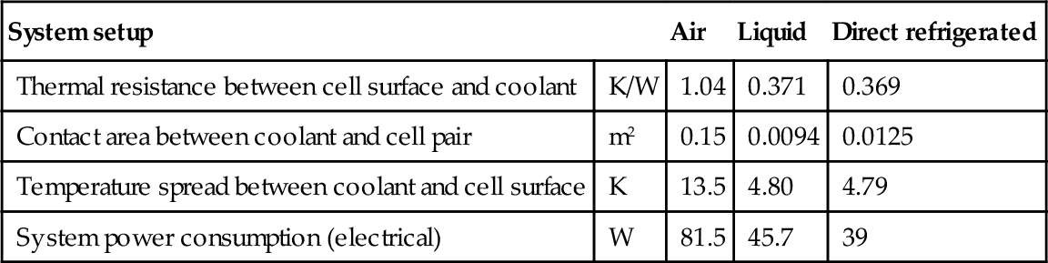
Although the exemplary calculations are highly simplified and do neglect additional features such as fans or pumps, they clearly highlight that especially for high-power applications, liquid and direct refrigerated systems are significantly more efficient than air-based cooling due to the superior heat transfer. As the limited heat exchanger efficiency and the waste heat of fans and pumps additionally add heat to the air- and liquid-based systems, the direct connection to the refrigerant cycle can be regarded as the most energy-efficient approach. Relevant case study results are summarized in Table 13.7.
Table 13.7
Summary of exemplary dimensioning case study
| System setup | Air | Liquid | Direct refrigerated | |
| Thermal resistance between cell surface and coolant | K/W | 1.04 | 0.371 | 0.369 |
| Contact area between coolant and cell pair | m2 | 0.15 | 0.0094 | 0.0125 |
| Temperature spread between coolant and cell surface | K | 13.5 | 4.80 | 4.79 |
| System power consumption (electrical) | W | 81.5 | 45.7 | 39 |
13.6 Technologies in comparison
General characteristics, strength, and weaknesses of the different thermal management systems are summarized in Table 13.8. Furthermore their particular appropriateness for special use cases as fast charging or battery swapping is evaluated. Table 13.9 lists selected commercial BEV/HEV and their respective battery-cooling concept.
Table 13.8
Overview on pros/cons of different battery cooling technologies
| Air based | Indirect liquid | Dielectric liquids | Refrigeration circuit | Thermo-electric | Phase change material* | |
| General aspects | ||||||
| Ease of use | ++ | − | + | + | ++ | ++ |
| Flexibility of package integration | + | ++ | − | + | + | ++ |
| Space needed | − | * | − − | + | + | o |
| Number of components | o | − | o | − − | ++ | ++ |
| Weight | + | − | − − | o | + | o |
| Thermal management efficiency | ||||||
| Max cooling power | − | + | o | ++ | − | − |
| Integration of heating | + | + | − | +/− | ++ | + |
| Conditioning uniformity | − | + | + | ++ | + | ++ |
| Interference w/other components | o | − | + | − | ++ | ++ |
| Economic considerations | ||||||
| Initial costs | ++ | o | − | − | o | + |
| Maintenance efforts | + | − − | − − | − | + | ++ |
| Lifetime | + | o | o | − | ++ | ++ |
| Eligibility for special use cases | ||||||
| Battery swapping | ++ | − | + | − | ++ | ++ |
| Fast charging | − | ++ | − | ++ | − − | + |
| Extreme climates | − | + | − | ++ | − | + |

++: Clearly superior; +: superior; o: neutral; −: inferior; − −: clearly inferior.
* Only as a secondary system, assisting the main thermal management.

13.7 Operational aspects
Cell temperature and humidity have to be monitored independently of the selected cooling system, and system behavior has to be adapted to load level and ambient conditions. With battery packs and use scenarios getting more and more complex, operational aspects of the battery thermal management gain importance.
13.7.1 Sensoring and control
Battery management slaves are widely used to monitor the single temperatures within the battery pack and forward the gathered values to the battery management master via a bus system (e.g., CAN). Currently the most common types of sensors used are externally mounted thermocouples or resistance temperature detectors (RTDs). The number and accuracy of sensors varies between battery packs, thus there is a remarkable trend toward a reduced number of sensors due to cost pressure. Given that, smart positioning of the sensors and a reliable interpretation of the values gain substantial importance and are subject to further research. On a laboratory scale are further endeavors to integrate sensors directly into the cells or meter the temperature indirectly, for example, via electrochemical impedance spectroscopy (Raijmakers et al., 2014).
13.7.2 Condensate avoiding and handling
When operated in hot and humid climate, basically all presented systems have to cope with the risk of condensate formation at the coldest spots within the cooling system. As it dramatically increases the risk of short circuits and accelerates the corrosion of system components, measures have to be taken to safely prevent condensation or handle incurring condensate. Characteristic criteria for the risk and amount of condensation is the dew point; this defines the temperature of the air at which point water vapor condenses. Dewpoint level over temperature and the air’s water content is given in Figure 13.15. The dew point curve clearly defines the area of oversaturated air. In case, for a known water content of supplied air, there is one spot within the battery pack with a temperature low enough to be above the dew point line, condensation will occur.

For basically all liquid-cooled or refrigerant-based systems it’s advisable to reduce the dead air volume within the battery casing and seal it against environment according to the typical automotive ingress protection (IP) rating. For the outer casing, ratings of IP 67 and above are to be achieved. Within the casing, all potential cold spots, as coolant supply lines, should be thermally insulated against the surrounding air.
There are also ways to actively control the humidity within the battery casing. For air-cooled systems this can be automatically achieved by using the dehumidified air originating from the HVAC. For enclosed air-tight systems an electrolyzer-based dehumidifier can also be integrated into the casing. However, as those systems consume approximately 8 W for removing 1.5 g of water from the air within 1 hour, they are limited to smaller isolated casings.
13.7.3 Pre- and postconditioning
Challenging ambient conditions can require battery preconditioning before vehicle operation. Preferably this is done while the vehicle is still connected to the charging station to use stationary power instead of battery energy. For hot ambient conditions, it can be advisable to start with a battery temperature as low as possible (within a safe range) to reduce cooling efforts during the journey and thus increase range. Very cold ambient temperatures suggest starting at higher temperatures to avoid additional battery heating during the journey as long as possible (Wehner and Ackermann, 2011).
13.7.4 Impact of electrical insulation
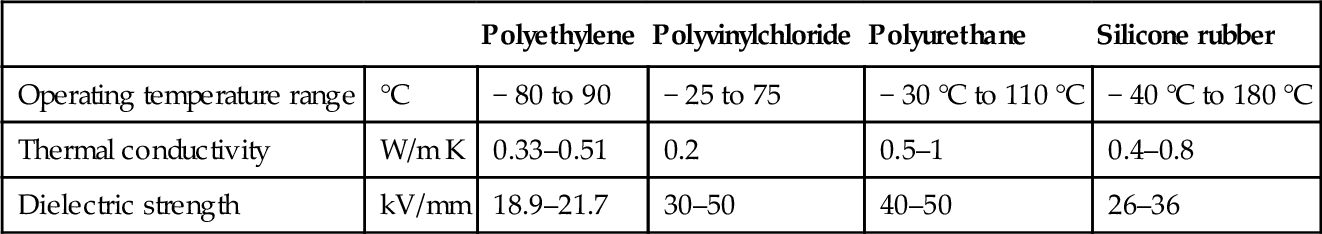
Another aspect of thermal management that is easily underestimated is the impact of electrical insulation. For safe operation all live parts have to be electrically insulated against the environment and adjacent parts. This can significantly influence the thermal management concept, as virtually all electrically insulating materials are also very limited in their ability to conduct thermal energy. Table 13.10 gives an overview of the thermal properties of the most common materials (Shugg, 1995). Their limitations in terms of temperature range and conductivity must be considered when designing the overall layout, as they are likely to be the bottleneck along the heat flow path.
Table 13.10
Thermal properties of common materials used for electrical insulation
| Polyethylene | Polyvinylchloride | Polyurethane | Silicone rubber | ||
| Operating temperature range | °C | − 80 to 90 | − 25 to 75 | − 30 °C to 110 °C | − 40 °C to 180 °C |
| Thermal conductivity | W/m K | 0.33–0.51 | 0.2 | 0.5–1 | 0.4–0.8 |
| Dielectric strength | kV/mm | 18.9–21.7 | 30–50 | 40–50 | 26–36 |
13.7.5 Limitations and challenges
Today’s environment for automotive batteries is already clearly limited by the cell’s thermal properties. This is most obvious for operation in extreme climates, where a significant amount of the usable energy is consumed just for thermally conditioning not only the cabin but also in the battery. This consequently results in a reduced driving range, which customers are not willing to accept. In addition to the absolute amount of heat within the battery pack, another factor can drastically restrict available power. Even with a powerful cooling infrastructure the heat flow from the cell core to the heat sinks can evolve to a bottleneck due to the low through-plane thermal conductivity of most cells (approx. 0.2 W/mK). This problem requires special attention for larger cells, which are favored by many manufacturers due to the lower connection complexity. To overcome this problem, additional heat pipes in between the cells or a cooling via the cell tabs can be necessary. The process of cooling via the cell connectors will have a certain impact, as the materials used (copper and aluminum) both offer high thermal conductivity and could therefore help to cool the cell literally from the inside. The approach is still subject to further research, as there obviously is some conflict of objectives between a good thermal contact between coolant and cell connectors and a reliable and safe electrical insulation.
13.8 Future trends
On a midterm perspective, lithium-ion chemistry is highly likely to be the dominant technology for electric vehicle batteries. With electric vehicles moving from a niche to a mainstream product, customer demand for shorter charging times make higher system currents necessary. Hence heat dissipation challenges are likely to further increase, making concepts specially adapted to fast charging applications a key success criteria (Jones, 2013; IPTS, 2010). It can therefore be assumed that thermal management tasks related to the battery will gain more importance within the next years and might also account for a higher cost-fraction in future cars. To cover these requirements in an economical way, new smart solutions as phase change material, conductor cooling, or an external supply of cooling media during charging will be necessary.
Some studies anticipate there will be 20 million electric vehicles on the road by 2020, covering all regions of the world (Trigg and Telleen, 2013). A wider adoption of quality electric vehicles also leads to more data on the batteries’ actual aging behavior and its dependence on operation temperature. Once the detailed impact of temperature spread and temperature variation history on the battery lifetime is known with statistical significance, thermal management systems can be adjusted to operate at a reasonable compromise between technical effort and impact on battery life.
Over the long run, new technologies might be on the rise, such as chemistries specifically designed for the fast-charging application, overcoming the problem of high thermal dissipation. This could be achieved by a significantly reduced heat release, an improved thermal conductivity within the single cells, or a less temperature-sensitive composition. A first trend in this direction is visible with LTO and LFP chemistries showing favorable fast-charging behavior (Pistoia, 2013), unfortunately still at the price of a significantly lower energy density. Large-scale availability of serious solutions is not expected to arrive before 2020 to 2030 (Anon, 2010; RECHARGE—The European Association for Advanced Rechargeable Batteries, 2013).
13.9 Sources of further information
Numerous institutes and research centers specialize in thermal management of batteries; they frequently publish reports and scientific updates. Among these are:
![]() National Renewable Energy Laboratory (NREL), Golden, Colorado
National Renewable Energy Laboratory (NREL), Golden, Colorado
![]() Joint Center for Energy Storage Research (JCESR), Argonne, Illinois
Joint Center for Energy Storage Research (JCESR), Argonne, Illinois
![]() SAE International, USA
SAE International, USA
As the topic also is researched at numerous universities worldwide, academic publications are also available within related journals, such as the Journal of Power Sources or the Journal of the Electrochemical Society.