Electric road vehicle battery charging systems and infrastructure
B. Lunz1,3; D.U. Sauer1,2,3 1 Institute for Power Electronics and Electrical Drives (ISEA), RWTH Aachen University, Aachen, Germany;
2 Institute for Power Generation and Storage Systems (PGS), E.ON ERC, RWTH Aachen University, Aachen, Germany;
3 Jülich Aachen Research Alliance, JARA-Energy, Aachen, Germany
Abstract
An adequate charging infrastructure is important for the market introduction of electric vehicles as they have to be recharged almost every day. In this chapter mobility statistics are analyzed to derive requirements on charging infrastructure. Charging infrastructure is classified according to different dimensions and advantages and disadvantages of contrary system solutions are discussed. A discussion of future trends and market forces completes this chapter.
17.1 Introduction
In contrast to fuel-powered cars, electric vehicles1 have to be recharged almost every day as the energy content of vehicle batteries is much smaller than the energy content of fuel tanks. An adequate charging infrastructure is thereby important for the market introduction of electric vehicles. But what is an adequate infrastructure? The range of solutions is very broad and the solutions have several dimensions. Important issues are as follows:
1. Infrastructure location: private or public.
2. Charger hardware: unidirectional or bidirectional.
3. Charging power: slow or fast charging.
4. Charging plug: one-phase plug without communication or combined ac/dc plug with communication.
Due to that complexity, the chapter starts with an analysis of mobility behavior in Section 17.2 to derive some general requirements on charging infrastructure, independent of the topics named above. Typical trip lengths, pause times, and parking locations are analyzed based on mobility statistics. Section 17.3 classifies charging infrastructure according to the dimensions listed above and summarizes their main characteristics. Advantages and disadvantages of different charging infrastructure solutions are discussed in Section 17.4. The discussion is focused on fast charging in contrast to slow charging and inductive (wireless) in contrast to conductive (with wire connection) charging. Important safety aspects are summarized in Section 17.5. Section 17.6 discusses market forces and future trends. The interdependence of charging infrastructure economics and the market development of electric vehicles is investigated. Important standards under development are summarized, and an outlook on the development path of electric vehicle charging infrastructure is given.
17.2 Mobility behavior and charging infrastructure
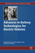
Statistical assessments help to identify the needs and the behavior of car users (Hackbarth et al., 2011). All conclusions given in this section are made for the average user and therefore give hints for the design of cars and charging concepts for a mass market. The analysis of mobility data is focused on Germany, but the general conclusions are similar for countries with analog mobility behavior, that is, for example, the case for most European countries, the United States, or Canada (see also Figure 17.1).

17.2.1 Driving behavior
The typical driving behavior is addressed first. The average driving distance per year is approximately 13,150 km (BMVBS, 2002); per day it is approximately 36 km. When we do not consider the days during which the cars are not moved, the average driving distance is 46 km (BMVBS, 2002). Figure 17.1 shows the fraction of trips, which are driven on distances up to a certain length and the total vehicle mileage traveled (VMT) on day trips up to a certain length. The fraction of VMT is smaller than the fraction of trips, as few longer trips have a higher impact on the VMT distribution than many short trips.
Single trips (trips between two stops) and day trips (all trips during one day) can be distinguished. The differentiation allows the driver to make fuel saving estimations for the possibility of recharging after every trip (applies for single trips) and for the possibility of recharging overnight (applies for day trips). In 95% of the cases single trips are shorter than 42 km and day trips are shorter than 150 km. The fraction of VMT allows estimating the fuel substitution when using electric vehicles (EVs) with a certain battery range. Assuming that trips longer than the battery range are driven using conventional cars, about 50% of VMT can be driven all electric, with a battery that allows for 80 km of electrical driving when the battery is only recharged overnight. If the possibility of recharging after every single trip exists, a fuel replacement of 73% can be reached with the same battery range of 80 km.
The all-electric operation or charge depletion (CD) mode fraction of PHEVs depending on the battery range is shown in Figure 17.2. The calculation is based on the trip distribution shown in Figure 17.1. All trips shorter than the all-electric range are driven solely electrically. Longer trips are first driven electrically until the end of the all-electric range is reached. For the rest of the distance the car is powered by its internal combustion engine in charge-sustaining (CS) mode.
We can conclude that a fuel substitution of approximately 50% can be reached for PHEVs with a battery that allows for 35 km of electric driving; an EV must have an electric range of around 80 km to reach the same fuel substitution (Figure 17.1).
For the charging operation of PHEVs and EVs, the following can be summarized:
![]() Overnight charging of a PHEV-50 (PHEV with 50 km all-electric range) is sufficient for over 70% of the days for pure electric driving and 60% of VMT.
Overnight charging of a PHEV-50 (PHEV with 50 km all-electric range) is sufficient for over 70% of the days for pure electric driving and 60% of VMT.
![]() Fast recharging after every trip increases CD-mode fraction by 17%.
Fast recharging after every trip increases CD-mode fraction by 17%.
![]() In 95% of the days, overnight charging of EV-150 (EV with 150 km battery range) is sufficient.
In 95% of the days, overnight charging of EV-150 (EV with 150 km battery range) is sufficient.
![]() With fast recharging possibility after every trip, 99% of the trips could be driven with an EV-150.
With fast recharging possibility after every trip, 99% of the trips could be driven with an EV-150.
All of the aforementioned points are made for the average car user. For specific applications, such as regular passenger service with a very predictable driving behavior, the consequences for battery dimensioning and charging can differ significantly. Battery sizing then can be made for the specific needs and also the access of charging infrastructure is more predictable.
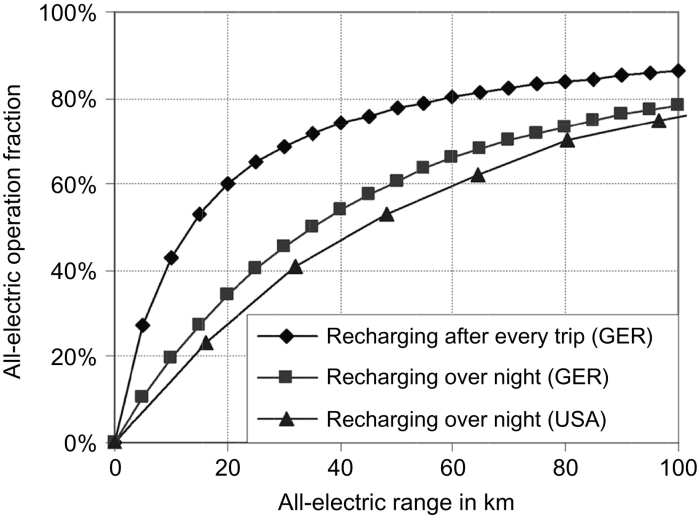
PHEVs that charge overnight at home is sufficient in general as the internal combustion engine can guarantee mobility also with a fully discharged battery. The focus of the investigations is therefore the proportion of pure electric driving with different stages of infrastructure expansion. Figure 17.3 shows the following potentials for pure electric driving for a PHEV-50:
![]() If only the possibility of recharging overnight exists, 60% of the annual mileage (VMT) can be covered electrically.
If only the possibility of recharging overnight exists, 60% of the annual mileage (VMT) can be covered electrically.
![]() With an additional possibility of recharging at work, approximately 66% of VMT can be driven electrically.
With an additional possibility of recharging at work, approximately 66% of VMT can be driven electrically.
![]() Additional charging infrastructure at shopping centers increases the share to 68%.
Additional charging infrastructure at shopping centers increases the share to 68%.
![]() 72% of VMT can be covered when charging during leisure activities is additionally possible.
72% of VMT can be covered when charging during leisure activities is additionally possible.
![]() A comprehensive charging infrastructure would increase the share of pure electric rides to 77%.
A comprehensive charging infrastructure would increase the share of pure electric rides to 77%.
It can also be concluded that a charging infrastructure with charging powers higher than 3.7 kW increases the share of electric driving only marginally (dashed lines in Figure 17.3). This conclusion is also valid for pure electric vehicles (Kley et al., 2010).
17.2.2 Pause times
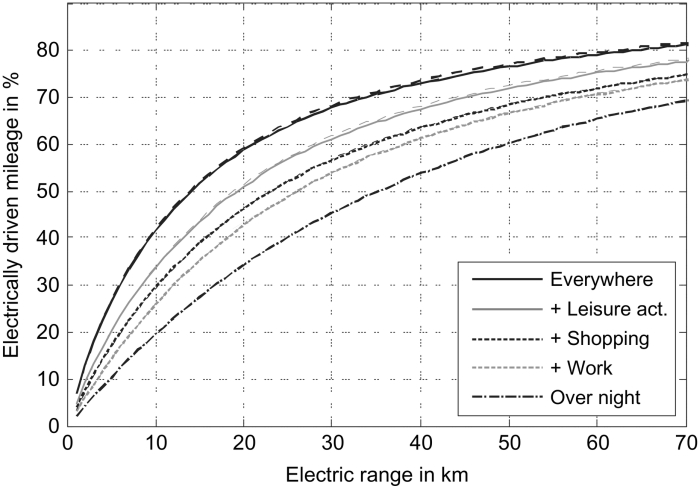
For the analysis of the needed recharging technology, the distribution of the pause times, shown in Figure 17.4, is relevant (Lunz et al., 2010a,b). Obviously many short pauses occur. For example, 40% of all pauses are shorter than 60 min, which may be an argument for the introduction of fast-charging technology. To analyze this in more detail, the correlation between the length of the pauses and the driven kilometers of the trip before was investigated. The result can be seen in Figure 17.5. There is a strong dependency of the pause time and the previous trip length: short stops obviously also imply only small driven distances before the stop.

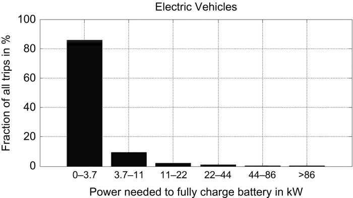
With an energy consumption of 18 kWh/100 km, which is typical for medium-size electric vehicles, it can be calculated how often a specific charging power is needed to guarantee a sufficiently charged battery for the next trip. For guaranteeing that, the energy consumed during the next trip has to be recharged during the pause time. Figure 17.6 shows the percentage of trips that can be covered with a certain charging power range. It can clearly be seen that the standard charging power of 3.7 kW is sufficient for approximately 85% of the cases. Another approximately 10% can be covered by three-phase, 16 A charging (11 kW). It can be concluded that fast charging is needed only very rarely and that all extra costs for a more complex battery design and the fast charging stations have to be justified by just a small number of fast charging operations or by the additional fuel substitution.
Taking into account the fact that it is not necessary to have a fully charged battery after each pause it can be seen from Figure 17.1 that it is sufficient to recharge an EV-150 overnight only 95% of the days of a year. For overnight recharging standard charging with 3.7 kW is sufficient in almost all cases for an EV-150. Also from a technical point of view, it can make sense not to fully recharge the battery after each trip as higher battery SOCs can cause faster battery aging for almost all of the different Li-ion chemistries; see, for example, Käbitz et al. (2013).
17.2.3 Parking locations
Another important aspect with regard to charging infrastructure is the typical location where cars are parked overnight (shown in Figure 17.7). Almost 60% of the cars in Germany are parked in a garage and a further 30% are parked in front of the home.

According to Wietschel et al. (2013), electric mobility is especially interesting for car users in rural areas and small- to mid-size cities. These users (e.g., around 30% of private car users in Germany) drive regularly large distances for commuting, which is the most economic use case for electric vehicles. Exactly in rural areas and smaller cities many car users park their car in a garage or directly in front of home so that no expensive infrastructure investments are necessary. During the rollout of electromobility, a focus should be on these 90% of households with easy access to a charging point. For the remaining 10% of vehicles, a complex public infrastructure, especially in larger cities, will be needed.
17.3 Classification of battery charging systems and infrastructure
Electric vehicle charging infrastructure can be classified according to different dimensions such as the location of charging infrastructure, used charger hardware, charging rate, and used plug types.
17.3.1 Infrastructure location
Requirements of EV charging infrastructure strongly depend on the place in which the infrastructure is located. Three different cases can be distinguished (Lunz et al., 2010a).
17.3.1.1 Private places
Overnight charging at home will be the most usual situation for electric vehicles as shown in Section 17.2. In the majority of cases the recharging time overnight is long enough to fully charge batteries of electric vehicles with longer range. The charging power can be limited to 3.7 kW, which is the most economical solution. Only little effort is needed to protect the infrastructure from vandalism or misuse as it is installed in a protected area.
17.3.1.2 Semipublic places
A semipublic charging infrastructure is one that is installed in a private area but can be accessed from a multitude of users. Examples are in car parks, company parking areas, and shopping mall parking grounds. Figure 17.3 shows that installing a charging infrastructure at work is the most promising way to increase the electrically driven mileage. As the absolute gain is still rather small, the infrastructure has to be deployed in a cost-efficient way. Companies, for example, could refrain from billing the electricity to the individual driver to reduce infrastructure costs on the one hand and to incentivise electric mobility on the other hand.
Additionally, Figure 17.3 shows that the potential for recharging at shopping malls is very small. Infrastructure deployment at these places therefore remains primarily a marketing measure to increase the attractiveness. The effect of charging infrastructure at recreational facilities is much higher, but these locations are widespread and thus installations there would cause high infrastructure costs.
17.3.1.3 Public places
Charging infrastructure on public ground can be fast-charging facilities on highways, battery exchange stations, and charging points for on-street parkers. This kind of charging infrastructure is most expensive as authentication and billing systems have to be installed and measurement devices must be calibrated. Furthermore, measures against vandalism have to be taken. Depending on the location a new grid access point has to be established.
17.3.2 Charger hardware
Basically, onboard, off-board, and wireless chargers can be distinguished (refer to Figure 17.8). All charging systems can be supplied by one-phase or three-phase voltage and, in general, every charging system can be uni- or bidirectional. Because of the higher power rating of off-board chargers, these systems are normally supplied by three-phase voltage.
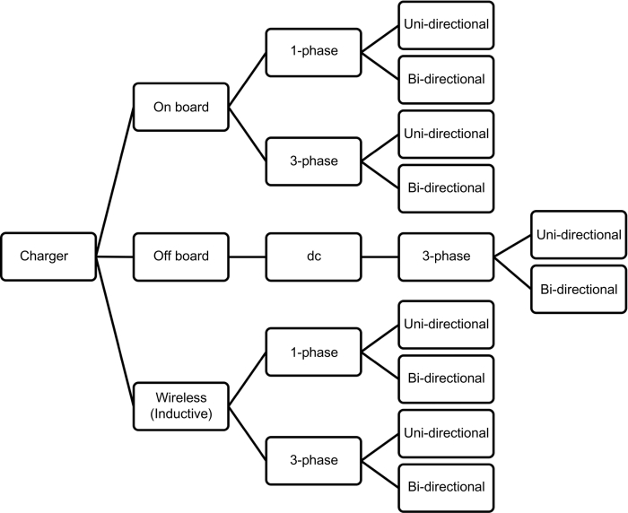
With unidirectional chargers power can flow only from the grid into the battery. A bidirectional charger is also capable of feeding power back from the battery into the grid. The simplest charger configuration is the single-phase unidirectional charger, and the most complex charger is the three-phase, bidirectional wireless charger. With the different chargers, grid services can be delivered to a different extent. Delivering grid services is named vehicle-to-grid (V2G) in this context.
For small charging powers up to about 11 kW, onboard chargers are the most suitable option. The advantages of these chargers are the possibility of customizing them for the specific battery pack used and the fact that recharging is possible on standard power outlets. A disadvantage of onboard chargers is that they have to comply with strict automotive standards. Further, they require space and increase the weight of the car. The extra weight can be reduced when the drive inverter is used for recharging (Haghbin et al., 2013).
For higher charging powers, dc charging stations become an interesting option. The charging power is transferred to the vehicle battery via direct current. The power electronics of these chargers are located outside the car (off-board), which reduces the weight and space requirement in the car. With off-board chargers the user is not able to recharge at standard power outlets, which might be problematic for user acceptance especially for EVs.
With wireless (inductive) charging systems energy can be transferred without galvanic connection. The stationary part of the charging system consists of power electronics that produce a high-frequency magnetic field. The receiver mounted in the electric vehicle consists of a receiver coil and a power electronics system producing direct current for battery charging. With these separated power electronics parts, wireless charging systems are a mixture between on- and off-board chargers. The working principle of inductive power transfer (IPT) (refer to Figure 17.9) is similar to a transformer with a large air gap and therefore poor magnetic coupling and high leakage flux (Yilmaz and Krein, 2013).

17.3.3 Charging rate
Charging infrastructure can also be classified according to different charging modes defined in IEC 61851-1 (NPE, 2013a,b), which result in different charging rates. The charging modes vary primarily in charging power and security level.
17.3.3.1 Mode 1
Charging in Mode 1 uses the standard power outlet without any further safety equipment. Therefore the household electric installation has to guarantee a safe charging process.
17.3.3.2 Mode 2
For Mode 2 charging the charging cable that connects the electric vehicle and the standard power outlet is equipped with an in-cable control and protection device (IC-CPD). This device contains a residual current protective device (RCD) and a communication module. The user is protected from electric shock even if the household electric installation has no RCD and the communication module sets the charging power of the car by a PWM2 signal. Furthermore, the earth conductor is monitored.
17.3.3.3 Mode 3
For Mode 3, charging a permanently installed wallbox (Electrical Vehicle Supply Equipment, or EVSE) is needed. The wallbox communicates with the car by PWM according to IEC 61851-1 or by power line communication (PLC) according to ISO/IEC 15118. With that the charging power can be set with respect to the electric installation. The wallbox consists of a communication module, an RCD, a circuit breaker, and a dedicated charging socket.
17.3.3.4 Mode 4
Mode 4 is dc charging with an external charging device. The charging operation is controlled by the vehicle. The external charger communicates with the car to set the right charging voltage and current. For charging Mode 4 the connection cable between the vehicle and stationary charger is fixed permanently to the charging point. The connector pins have to be rated for currents above 100 A, and the connection has to be locked during the charging operation. The different charging modes and their characteristics are summarized in Table 17.1.
Table 17.1
Overview on charging modes in IEC 61851-1
| Charging mode | Maximum current | Max. charging power | Charging time for recharging ca. 20 kWha |
| Mode 1 | 16 A ac, 1-phase | 3.7 kW | 5 h |
| Mode 2 | 32 A ac, 3-phase | 22 kW | 1 h |
| Mode 3 | 63 A ac, 3-phase | 44 kW | 0.5 h |
| Mode 4 | 400 A dc | approx. 200 kW | 6 minb |

a Sufficient for ca. 100–150 km electric driving.
b Without charging in constant voltage phase up to approx. 80% SOC.
17.3.4 Plug types
Different plug types are defined in IEC 62196, which differ in dimensions and current/voltage rating. Although international standards exist, different plug types are used in different regions of the world (see Figure 17.10).
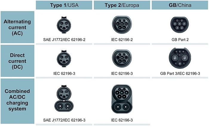
In IEC 62196-2 three different plug types are distinguished for ac charging:
The type 1 single-phase vehicle coupler is primarily used in the United States and Japan and adopts specification from SAE J1772/2009. The plug is suited for maximum 7.4 kW at 230 V ac (Rarbach, 2013).
The type 2 single- and three-phase vehicle coupler (invented by the German company Mennekes, therefore also called a Mennekes plug) in IEC 62196-2 adopts specification from VDE-AR-E 2623-2-2 and is able to transfer up to 43.5 kW at 3-phase 400 V ac. Also dc charging with up to 80 A is possible with the type 2 plug.
The type 3 plug was developed by the EV Plug Alliance consisting of companies from France and Italy. It is a single- and three-phase vehicle coupler with shutters. As the European Commission defined, the type 2 plug is standard in Europe for electric car charging, and the type 3 connector now is mainly used for light electric vehicles (e.g., scooters) (Anthony, 2013).
Dc charging is defined in IEC 62196-3. The two most important plug types are CHAdeMO and the combo plug. The CHAdeMO (CHAdeMO, 2013) plug can transfer up to 62.5 kW at 500 V and 125 A dc. It is a quasi-standard in Japan, and many Japanese cars are equipped with this connector (e.g., Nissan Leaf, Mitsubishi i-MiEV).
The combo plug combines a type 1 or a type 2 plug with two dc contacts. European car manufacturers (BMW, Daimler, Ford, General Motors, and Volkswagen) agreed to use Combo2 plugs in future cars. This is called a combined charging system (CCS), which allows for up to 200 A dc (PHOENIX CONTACT, 2013).
17.4 Advantages and disadvantages of the solutions for battery charging systems and infrastructure
The discussion of advantages and disadvantages of different charging solutions is focused on fast charging in contrast to slow charging and inductive (wireless) in contrast to conductive (with wire connection) charging.
17.4.1 SWOT analysis for fast charging in comparison to standard charging
In the following section, a SWOT analysis is performed for the technology of fast charging to identify the strengths, weaknesses, opportunities, and threats with regard to that charging method (Lunz et al., 2010b). The strengths and weaknesses relate to technical issues and are also called internal factors, whereas the opportunities and threats focus more on the user and general conditions; these are called external factors. Table 17.2 gives an overview of the results of the SWOT analysis for fast-charging technology. In the following, the different aspects in the table are explained.
Table 17.2
SWOT analysis for fast charging technology
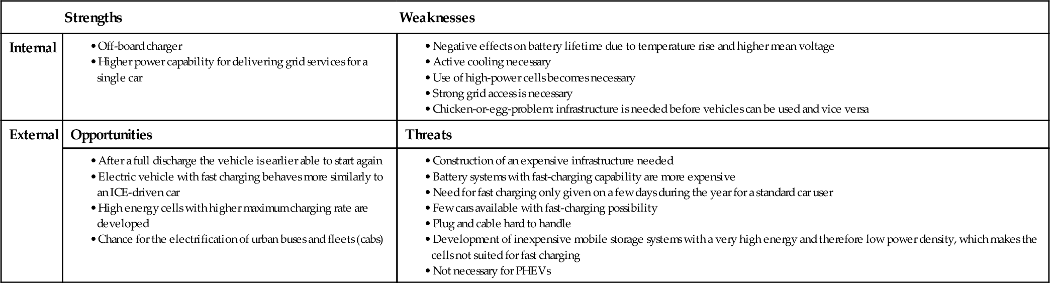
It becomes obvious that fast charging has only very few technical strengths. The higher power rating of the connection increases the power capability for grid services for a single car. Due to the higher power rating the delivery can only be guaranteed for a shorter time. As the power electronics of a fast charger are normally located in the charging station and not in the car, a small weight reduction can be reached and the off-board charger does not have to comply with the strict automotive standards.
As negative internal factors, the effects on the battery system have to be addressed. Because of the higher losses and therefore the higher battery temperature during fast charging, the battery lifetime is negatively affected (Vetter et al., 2005). By applying higher currents to the battery, the mean voltage during the charging operation is higher compared to a standard charging method. A more complex cooling system is necessary to overcome the battery degradation through the temperature rise. In case of standard charging, an air-cooling system might be sufficient, whereas for fast charging the use of water cooling or the use of refrigerants become necessary. This, of course, increases the battery system weight and also the costs. In an EV, normally high-energy cells are used that can deliver enough power for the driving operation of the car. High-power cells are required to achieve very high charging powers. That means that the battery system design is then defined by the charging operation. High-power cells have a lower energy density, and therefore more material has to be used for the same storage capacity. This leads to higher costs for these cells.
For fast-charging stations a strong grid access is necessary. The required connecting power is not available everywhere, which causes extra investments for the grid infrastructure. A fast-charging station with three 200 kW chargers, for example, needs an extra transformer on the medium-voltage grid. Furthermore, a chicken-or-egg problem exists: Either a fast-charging infrastructure is needed before the vehicles can be used, or vehicles capable of fast charging have to exist before the infrastructure is built.
When it comes to the external factors that might influence the introduction of fast-charging technology, the user acceptance first has to be addressed as an opportunity. Car drivers are used to the nearly unlimited driving range of their internal combustion engine (ICE) vehicles. In the introduction phase of marketing electric vehicles, it could be beneficial to generate the same feeling by providing drivers with fast-charging stations.
Another driver for fast charging could be the development of cells with high energy density and, at the same time, high charging capability. This would overcome the problem of over-designing the battery pack only to achieve fast charging. Unfortunately, high power and high energy are mutually exclusive.
All discussions thus far referred to standard passenger vehicles. However, there are other applications, where fast charging is an interesting and worthy option. A sector where fast charging would make sense today is in urban bus traffic and vehicle fleets such as cabs and delivery vehicles. In contrast to the driving behavior shown before, these vehicles drive more kilometers per day and the duration of trips are easier to plan. In this scenario, the batteries for buses do not have to be designed to hold all the energy needed for one day. When the bus is fast-recharged three times a day, for example, only a fourth of the net battery size is required.
We must, however, mention the high costs for the infrastructure required for fast charging. The costs are mainly for the grid access, power electronics, and connectors of the charging station. It is unclear what kind of company or business can support a fast charging station if it is only needed rarely. As cars with fast-charging capability are going to be more expensive than cars with only standard-charging capabilities, it may be the case that only few car manufacturers will equip their cars with the fast-charge technology. This could make the business model for fast-charging station operators even more doubtful.
Another problem with promising vehicle users fast-charging options is that they may make use of this option once a year or so, for vacation or traveling over the holidays. This would require an infrastructure designed for these extreme peak loads for a very few days in a year. This infrastructure would be extremely expensive and it is unclear who would pay for it.
From a user’s perspective the fast-charging plugs can be hard to handle. A plug connection that can transfer powers above 100 kW is always relatively heavy and complicated to use due to the needed conductor diameter in the plug itself and in the cable. Another threat for fast-charging technology is the development of inexpensive batteries with a very high energy density. With that, electric vehicles with a longer driving range become possible and make fast-charging stations needless.
Fast-charging stations are not really needed for PHEVs. The ICE of a PHEV always guarantees the mobility of the car user even if the battery is fully discharged. With fast charging only a very little gain in the all-electric operation fraction can be reached which does not justify the higher costs and complexity to make a PHEV capable for fast charging.
17.4.2 SWOT analysis for inductive in comparison to conductive charging
Three different inductive charging systems can be distinguished:
1. Charging system with low distance transducers. This system works similarly to most electric toothbrushes. A high-frequent magnetic field is produced in the primary transducer (in the case of GM’s EV1 this was a paddle) and the secondary transducer is mounted as a charge port in the vehicle (in the case of GM’s EV1 a charging slot). The paddle is connected to the stationary power electronics by a wire and the user has to insert the paddle manually into the vehicle charging slot. Another type of this charging system has the secondary coil mounted under the license plate and the primary coil mounted on the wall. During charging the vehicle has to be placed with its number plate and wall-mounted primary coil against each other. The major advantage of this charging system is the lack of galvanic contacts; therefore there is no wear on the contacts and there is a high electric safety due to a complete electric insulation of primary and secondary coils.
2. Stationary inductive charging with larger distance. The electrical principle of this system is the same as described above. The vehicle-mounted receiver coil is placed on the vehicle floor. The primary coil is embedded in the parking lot floor. During charging the vehicle-mounted receiver has to be placed directly above the floor-mounted primary coil. Automatically positioned or adjustable systems can assist in this process and increase the alignment precision. These systems can also be used, for example, at bus stops to recharge the battery during loading or unloading of the passengers.
3. Inductive charging during driving. Inductive charging during driving is the most advanced system. The vehicle-mounted secondary coil remains similar as described above. The street-mounted primary coil can be a long wire loop, sectional loops, or spaced loops (Yilmaz and Krein, 2013) integrated into the pavement. With this system electric vehicles can be recharged during driving, which reduces needed battery sizes.
With a SWOT analysis (Table 17.3), the advantages and disadvantages of inductive charging in comparison to conductive charging are investigated. The technical strengths of inductive charging mainly are in the field of safety. Due to the wireless energy transfer no electrical contacts are needed, which can be touched or get broken due to wear. Another strength is a higher protection against environmental impacts or vandalism as the transducers can be mounted under a solid surface. Due to the principle of energy transfer by a magnetic field, galvanic isolation is guaranteed under all operation conditions, which reduces electrical hazards.
Table 17.3
SWOT analysis for inductive charging technology

Technical weaknesses can be found in the area of efficiency and compactness. Due to a large air gap the power transmission efficiency is lower compared with conductive charging. In fact, the efficiency can be increased by using resonant topologies (Yilmaz and Krein, 2013); this increases technical complexity also. The overall complexity of inductive charging systems is higher in general, as an additional high-frequency converter is needed on the infrastructure side and a rectifier on the vehicle side (see Figure 17.11).

Due to that increased complexity, the size and the weight of the vehicle-mounted parts of the charging system are higher. A technical challenge is the positioning precision of the primary and secondary coil. This can be solved by automated systems which, of course, add complexity.
The higher complexity directly can explain the threats of inductive charging. The systems are costlier, and compatibility among different car manufacturers could be even more difficult to achieve than compatibility of plug systems. Another external threat for inductive charging is the development and rollout of automated conductive charging systems. These systems would combine the higher efficiency of conductive charging with the user-friendliness of inductive charging.
The user-friendliness of a fully automated charging is the biggest opportunity for inductive charging. With such a system the battery charging could take place more frequently, and subsequently vehicle battery sizes and battery costs could be reduced. If inductive charging occurred during driving, battery sizes could further be reduced so that fast-charging stations would not be needed. In some demonstration projects public buses already use inductive charging for frequent recharging on bus stops. This enables a fully electric bus system with reasonable battery sizes. Of course, that is also possible with automated conductive charging on bus stops that are also used in demonstration projects.
17.4.2.1 Safety considerations during charging
Safety during electric vehicle charging is an important aspect (Hackbarth et al., 2011). Current standardization for onboard chargers states that the vehicle chassis should be grounded during charging. Therefore, a solid, low-impedance connection between vehicle chassis and ground should be set. An integrated ground fault interrupter (GFI) can prevent injury to persons. The GFI constantly monitors the current flow in a circuit, sensing any loss of current. If the current flow through the circuit differs by a small amount from that returning, the GFI quickly switches off power to that circuit. In case of a contact between the vehicle chassis at false potential and the human body, the GFI interrupts power fast enough to prevent a fatal electric shock. The integrity of the ground wire connecting the vehicle chassis should be tested before charging is allowed to commence.
Another important issue is the question of galvanic isolation of the car’s electrical system. While the car is in driving operation, grounding of the vehicle chassis is not possible. The battery pack, traction inverter, and motor act as an isolated terra (IT) system. An IT system can still operate with one insulation fault, allowing the driver to move the vehicle to a safe place after a warning signal indicates the first fault. Only after the second insulation fault will there be a loss of current and the system has to be shut down.
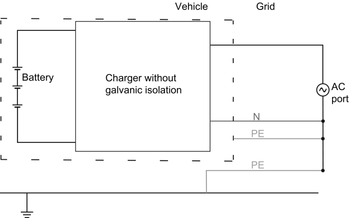
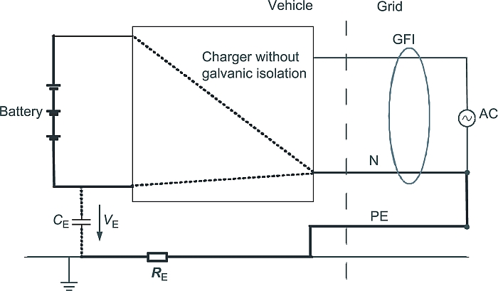
In charging operation, the battery pack, the charger (without galvanic isolation), and the grid connection no longer form an IT, but rather form a TN (Terre Neutre) system (Figure 17.12). Current will leak with the first insulation fault, which is a hazard if it is not shut down immediately. Further, depending on the charger’s topology and control, the potential VE of the battery to earth might fluctuate with switching frequency of the charger, leading to ground leakage currents through ground capacity CE (Figure 17.13). These ground leakage currents cause unnecessary losses and might additionally trigger external GFIs. If galvanic isolation is added to the charger, the conditions of an IT system are regained for charging operation. The price is an increase in volume, weight, and cost. Besides that, the efficiency of the charger will drop because of the transformer needed for galvanic isolation. The necessity of a one-fault tolerance while driving the vehicle is obvious. But while the car is being charged it is usually parked in a safe place such as a garage. A shutdown due to an insulation fault will not have severe consequences for the operator so that charging without galvanic isolation is a viable solution as well.
17.5 Market forces and future trends
The interdependence of charging infrastructure economics and the market development of electric vehicles is investigated. Important standards under development are summarized and an outlook on the development path of electric vehicle charging infrastructure is given in this section.
17.5.1 Economics of charging infrastructure and user acceptance
Infrastructure deployment and costs have a significant impact on the acceptance of electric vehicles. The interdependence of the existence of a public charging infrastructure and the user acceptance for electric vehicles is complicated and no general conclusion can be drawn from the literature. In some demonstration projects it was observed that the users want to have a dense public charging infrastructure, but when it was built up, it was only rarely used (Wietschel et al., 2013). A demonstration project in Tokyo with CHAdeMO fast-charging station showed that electric vehicles were used more frequently when fast charging was available (Takafumi, 2010). The drivers dared to drive longer distances because they knew that in case of a fully depleted battery they would be able to recharge it within 20 min. Despite the much farther driving distances, the quick charger was only rarely used.
These examples show that there is a desire for a public and also for a fast-charging infrastructure when the costs for the infrastructure are not taken into account. Wietschel et al. (2013) investigated the effect of charging infrastructure costs on the overall cost-effectiveness of electric vehicles. If costs for a public charging infrastructure have to be compensated by vehicle owners, electric vehicles are only competitive in very few use cases. The same is true for higher charging powers, as they do not increase the electrically driven kilometers for suitable users. If higher costs have to be covered by the vehicle owner, higher charging powers can even decelerate the market introduction of electric vehicles. The introduction of electric vehicles could be pushed if a semipublic charging infrastructure (car parks, etc.) is offered without extra costs for the vehicle owners. Until 2020 only little potential exists for on-street parkers as the needed charging infrastructure is too expensive. Costs for a public charging point with 3.7 kW power are estimated to be €1.700 with annual costs for maintenance and metering of €725 (Wietschel et al., 2013). The maintenance costs would approximately double the electricity costs if they were allocated to one electric vehicle. Maybe flat rates that do not require individual and calibrated metering can be offered at lower costs.
17.5.2 Standards and regulations
Standards and regulations are an important basis for the development of products. Especially newly defined standards or standards under development have to be observed carefully during the development process of charging infrastructure. The Technical Committee (TC) 69 “Electric road vehicles and electric industrial trucks” is responsible for the standardization of charging systems within the International Electrotechnical Commission (IEC). Besides updating valid standards, new standards in the following area are under development:
![]() EMC requirements for chargers (IEC 61851-21)
EMC requirements for chargers (IEC 61851-21)
![]() DC charging station and communication between vehicle and charging station (IEC 61851-23/24)
DC charging station and communication between vehicle and charging station (IEC 61851-23/24)
![]() Requirements on ac and dc charging, battery swap and communication for light electric vehicles (LEVs) (IEC 61851-3)
Requirements on ac and dc charging, battery swap and communication for light electric vehicles (LEVs) (IEC 61851-3)
![]() Wireless power transfer systems for vehicle charging (IEC 61980)
Wireless power transfer systems for vehicle charging (IEC 61980)
![]() Communication interface for vehicle to grid (ISO/IEC 15118)
Communication interface for vehicle to grid (ISO/IEC 15118)
17.5.3 Development path of charging infrastructure
The grid integration of electric vehicles will take place in different development steps (Lunz et al., 2010a). First, a development path for charging infrastructure is described.
(1) Charging at home: During the market introduction of electric vehicles charging at home with moderate charging power (max. 3.7 kW) will be the most probable case. For on-street parkers, charging solutions are only installed in a few locations, particularly developed via publicly funded demonstration projects.
(2) Charging at work: Companies are able to install a charging infrastructure with comparably low costs if they do not integrate billing systems. As shown in Section 17.2.1, a charging infrastructure at places of work has the highest potential among all recharging locations. A maximum charging power of 3.7 kW is the most economical solution for this use case.
(3) Charging at shopping malls and car parks: The availability of a charging infrastructure at these locations can attract consumers within a certain market share of electric vehicles. But only special markets with a zone of attraction of more than 20–30 km would really benefit from such additional charging infrastructure. Typical grocer’s shops have customers from nearby.
(4) Charging infrastructure for on-street parkers: This part of the charging infrastructure will be the last to be made available. This is because of the high infrastructure costs and only small operational profits due to low energy throughput. However, some companies have shown concepts at low costs for adding charging points to existing street lamps (Ubitricity, 2013).
(5) Fast-charging stations along highways (as planned by Tesla Motors Tesla, 2014): This kind of infrastructure would allow for long-distance rides with electric vehicles. Requirements for this system are fast-chargeable cars (less than 10 min recharging time) and a business model to operate this infrastructure. Problems with peak load design of this infrastructure, for example, for the beginning or end of a holiday, have been discussed above.
Depending on the market share of electric vehicles, charge management becomes necessary to avoid overloading the distribution grid. On the other hand, the integration of the vehicle batteries into the electricity market can generate additional profits for the vehicle owner by providing control power or taking part in energy trading, as summarized as Vehicle-to-Grid, V2G (Kempton and Tomić, 2005a,b,). For the successful grid integration of electric vehicles, different steps can be identified:
(1) Uncontrolled charging at home with moderate power (max. 3.7 kW) will be the dominating scenario at low market penetration of electric vehicles. For up to 1 million electric vehicles in Germany, for example, no grid restrictions are expected during charging if the vehicles are relatively evenly distributed (VDE, 2010). An accumulation of electric vehicles in areas with weak grid segments can cause problems already at this stage.
(2) The reduction of the charging power at frequencies lower than nominal grid frequency can contribute to frequency regulation in the grid (VDE, 2010). The easiest possibility in which to realize this behavior is a power reduction according to a static power frequency curve. For that no communication connection of grid operator and electric vehicle is necessary. The supply of reactive power can also be realized by static characteristics.
(3) The charging time of different vehicles in a distribution grid segment can be controlled by an appropriate charging management to avoid overloading the grid. Supplying smart meters with time-shifted variable price curves is one possibility to indirectly control the charging behavior of electric vehicles. Additionally, the vehicle charging management is then able to minimize charging costs by charging at times with low rate tariffs.
(4) Pooled electric vehicles supply frequency control power in the control power market. Positive as well as negative control power can be supplied by starting or interrupting the charging process. As a first approximation, the battery lifetime is not affected by this as no additional cycles occur. Precondition for pooling is a communication link between the vehicles and the aggregator.
(5) To supply control power even with a fully charged battery and to increase the potential for control power delivery, a bidirectional charger is necessary. Bidirectional power flow also enables energy trading and the supply of additional grid services. When using bidirectional chargers, effects on battery aging have to be taken into account depending on the application and used battery technology.
An additional application for electric vehicles could be increasing the self-consumption of photovoltaic (PV) energy. As the price for electricity consumption is much higher than the feed-in tariff for PV electricity, it is profitable to consume as much PV energy as possible directly in the household. With a suitable charging management of the electric vehicle, the charging time can be shifted toward peak production of PV energy.
17.6 Sources of further information
This chapter provides an overview of different aspects of battery charging systems and infrastructure. Due to the complexity of the topic only few details could be given. Further information can be found in the following:
Yilmaz and Krein (2013): The authors provide a detailed overview on battery charger topologies, charging power levels, and infrastructure. Especially different power electronics layouts are discussed for the different charging concepts.
IEC 61851: The standard “Electric vehicle conductive charging system” defines different charging modes and processes for electric vehicles.
IEC 62196: The standard “Plugs, socket-outlets, vehicle connectors and vehicle inlets—Conductive charging of electric vehicles” contains definitions of different charging connector systems.
NPE (2013a,b): This report of the German National Platform for Electric Mobility provides practical guidelines for the setup of an electric vehicle charging infrastructure. Topics covered are different charging modes, dimensioning of electric installations and the requirements on charging infrastructure and parties involved.
Schroeder and Traber (2012): This paper provides a detailed analysis of the economics of fast charging infrastructure in Germany from an investor’s perspective.
Wietschel et al. (2013): This study from Fraunhofer ISI analyzes rollout scenarios for electric mobility. Also aspects regarding charging infrastructure are treated.