
6 Equipment Inspection, Testing, and Diagnostics
6.1 INTRODUCTION
This chapter provides a summary of the basic methods with which an electric distribution utility can better judge the condition of its equipment: inspection, testing, and diagnostics. It is not meant to provide comprehensive coverage of electrical equipment testing methods and how to apply them: that would fill more than one book. This chapter is intended to review the scope of the field and to make points and provide a perspective on inspection, testing and diagnostics as part of aging power delivery infrastructure management programs.
This chapters begins with an overview of inspection and testing and their goals, in Section 6.2. The various types of tests and diagnostics applied to equipment are covered in Section 6.3. Equipment tests include a variety of methods to evaluate the electrical and mechanical capabilities of the units and to diagnose what might be wrong internally with a unit that gives Orr test results. Section 6.4 covers tests of insulating oil. Oil is used in a wide variety of power system equipment. Oil tests focus both on evaluating the condition of the oil itself, and on using oil and other test results to diagnose the internal condition of the equipment. Section 6.5 concludes with a summary of key points.
6.2 INSPECTION, TESTING, AND DIAGNOSTIC EVALUATION
To be effective, inspection, diagnostics, and testing must be coordinated and applied in a well-designed program that also uses the results from system operation (trouble reports) to identify overall equipment condition and performance, and that prioritizes preventive maintenance, repair, rebuilding, and replacement. Optimum results are derived by then loading equipment to levels determined based on its assessed condition, the loss of lifetime caused by the usage, and the available economic alternatives. Procedures for organizing and managing such programs will be discussed in Chapter 10. This chapter focuses on condition assessment inspection, diagnostics, and testing methods themselves. Inspection, testing and diagnostics are the means through which the condition of equipment is determined. These three types of condition verification all have different meanings.
Inspection involves evaluation of conditions based on visual, aural or equipment-supported inspection of a device or structure. Basically, one looks, and at times listens to or scans, the device to determine if it looks or sounds as if it is in good condition. This inspection may be augmented by equipment to enhance the detail or better quantify the results (infrared camera, microphone, and harmonic analyzer system). Good examples of this are the use of infrared scanners to identify equipment that is running hotter than normal, and devices that check the thickness of paint or galvanization of metal through scanning of the material.
Olfactory inspection can also be an aid in a few cases (“Do you smell something burning? Does this oil smell sooty to you?”) and is a big area for future development of inspection and test equipment. Sniffer machines, which can detect trace amounts of certain chemicals in the air or in a fluid, are being developed to augment inspection and testing of equipment. (At the present time the most frequently seen examples of these devices by the general population are the explosives sniffers used in security checks at airports.)
Another example of equipment-enhanced sensing for inspection is a practice at numerous utilities of leaving the radio of company cars tuned to the AM band while driving line routes for visual inspection of equipment. Cracked insulators, corroded brackets, and broken conductor strands create small amounts of radio interference, detectable as a sudden increase in “static” background noise by the radio when near them.
Testing involves checking the device and its associated support equipment (its system) to make certain it operates as it should, by checking to see that it can indeed function to specification, or for the presence of evidence that something is wrong. Thus, a breaker test involves making certain that it trips in the time and at the speed it should, and that it re-charges or re-sets itself as expected, and that its relay performs as “programmed.” A test of a line switch involves cycling it once to assure that it will open and close as expected. A transformer may be tested at full load, or merely monitored in detail during peak season and its data results (maximum temperature, rate of temperature rise, losses) compared to expected values. Any deviation would trigger diagnostics to determine what was wrong.
Diagnostics involve “tests” that measure factors other than those directly related to a device’s function: tests whose results provide clues to the device’s internal condition, the performance of subassemblies inside it, or the possibility of impending failure. Usually, diagnostics probe the condition of materials (e.g., insulation) and are tracked over time to determine the rate of deterioration or contamination. The amount and type of gas, and the rate of its increase over time, identify whether there are internal faults, arcing, or overheating inside the unit – problems with something other than with the oil itself. This makes them a diagnostic test, not strictly speaking, an equipment test.
“Test” can have two meanings
The word “test” has a somewhat confusing dual meaning with respect to electrical equipment, a fact compounded by the inexact use of the word on a day-to-day basis by many power systems professionals. There is a fine line between testing and diagnostics and two experienced test engineers may not agree entirely on whether a procedure is purely a test or a diagnostic test. This is not important as long as the data collected are used fully, correctly, and well. Strictly speaking “testing” of a device always refers to actions or steps performed to measure or verify its performance or characteristics against its functional specifications. Actions that check the unit to see that it has the correct turns ratio, that its losses, leakage, and thermal buildup are within spec, that it meets trip or operation timing, and that it meets any other specifications for its performance (noise) are tests of the unit itself.
However, many diagnostic procedures involve a “test” of a particular component or factor in the machine or equipment. For example, dissolved gas tests of transformer oil provide an indication of the condition of the oil itself and whether it can do its job, making them a “test” of the oil. However, dissolved gas tests of insulating oil done are done primarily because they are diagnostic – they provide powerful clues to the condition of a transformer’s winding insulation and the causes of problems therein: a clue to the condition of something other than what is being directly tested.
Thus a test of a component or part (transformer oil in this case) can take two forms:
1. Testing of the oil to determine if it performs its function. For example, dielectric breakdown test of transformer oil directly measures one aspect of the performance the oil is expected to provide (insulating ability).
2. Diagnostic tests. By contrast, the oil could be tested for acidity or by dissolved gas analysis (DGA). These tests respectively determine the content of acids in the oil (formed by oxidation) and the amount of gas dissolved in the oil. The former gives an indication of both the condition of the oil and the likely amount of sludge buildup in the transformer. The second test is widely regarded as the best possible early indicator of impending problems with the transformer itself.
Three Purposes for Inspection, Testing, and Diagnosis
Inspection, diagnostics, and testing fall into three different categories, with three different purposes:
1. Acceptance, or capability testing - new equipment is often tested to verify that it both is undamaged and ready for service, and that it meets specifications as to capability, losses, impedance, and a host of other factors important in its performance. Some of these tests may be the same as performed later during routine inspections or condition evaluation, but many are unique, one-time evaluations, such as a test for no load and load-related losses performed on new transformers, to verify what was built to specification.
2. Routine inspection – typically equipment in service is inspected, and perhaps some diagnostics or tests performed, on a periodic basis – annually, every three or five years, etc. This is done for what might be called “general principles” and because warranties may require it. The overall goal is to identify deterioration or damage before it becomes too serious to perform preventive maintenance, and to identify equipment that is about to fail in time to remove it from service in an orderly fashion.
3. Condition evaluation – on occasion, more comprehensive tests than called for on a routine basis are performed on some or all equipment to establish more precisely the condition of these units. The purpose of these tests is to identify as much as possible the condition of the equipment and any problems that might preclude its equipment being left in service with a high degree of confidence that it will perform its function dependably.
Often the line between routine inspection and more thorough condition evaluation is blurred. For example, routine inspection policies at some utilities call for mandatory follow-up testing of any equipment found to have possible problems. Their condition evaluation is considered a second-stage in routine testing; done only if it appears needed. Other utilities include as part of routine testing, through condition evaluation of randomly selected units, the goal being to test enough units to identify any trends of deterioration or deficiency endemic to all units in a certain class or category. Policy on inspection and condition evaluation is appraised and set, using methods that will be discussed later.
Field or Laboratory Evaluation
Inspection, diagnostic tests, and testing can be carried out in the field (where the equipment is installed) or in a laboratory or test facility. The advantage of field tests is that they can be done on-site, usually taking less time and involving less skill and expense than laboratory tests.1 However, generally the laboratory tests are more accurate and thorough.
For example, dielectric testing of transformer oil can be done either as a field test using the ASTM (American Society of Testing and Materials) D-877 disc electrode method, or as a laboratory test using the ASTM D1816 “VDE cell” method. The former involves testing samples of about one pint of fluid for dielectric breakdown strength, by placing the fluid in a small container in which two small disc electrodes are spaced .1 inch apart. Higher and higher voltages are applied until the oil breaks down. The entire test takes but half an hour and uses a portable device the size of a small suitcase that is taken to each transformer to be tested. By contrast, the D1816 “VDE cell” dielectric breakdown test of oil is done in a laboratory. It involves testing a larger sample of fluid drawn from each transformer and taken to the laboratory, in a “VDE cell” within which the oil is circulated, with test electrodes that more closely mimic the field strength and uniformity of voltage seen inside a transformer. This test is regarded as more accurate in depicting electric strength and scatter than the disc electrode test, but it takes more time for the test itself, and for collection of materials and running back and forth from the field to the laboratory.
Non-Destructive, Destructive or Forensic Tests
Testing methods can also be categorized by the condition of the device or equipment being tested before and after the evaluation, as shown in Figure 6.1.
Destructive tests ruin or damage the device or equipment. Afterwards, the entire device, or a portion of what was tested, is damaged and not suitable for service and may in fact have been completely destroyed. Examples are (for cables in this case) voltage breakdown testing of a section of cable carried out to the point of failure, to determine its dielectric strength and mode of failure, and inspection of samples of cable for treeing. The former destroys the cable section being tested. The latter removes part of the cable (which must be repaired).
Destructive tests are generally carried out by manufacturers on new equipment to verify strength and identify failure modes. Utilities use the tests on select samples of equipment that have been in service, in order to determine the rate of deterioration of various components. These tests are often applied to cables, switches, and service transformers. Usually, equipment that is destructively tested is damaged to the point of having no further value. Regardless, this equipment should never be returned to service after the tests, unless it is part of an experiment on durability, etc.
1 At least if the cost of equipment is not included. Often field tests require specialized diagnostic equipment whose cost can be quite high, whereas laboratory tests for the same or similar factors would involve only standard laboratory equipment.
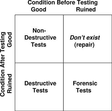
Figure 6.1 Diagnostic and testing methods can be categorized by the condition of the equipment before and after the tests.
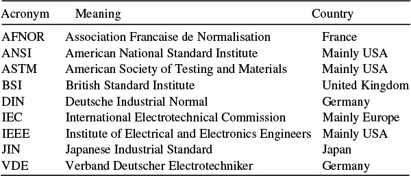
Table 6.1 Standards Bodies with Guidelines or Recommended Testing Methods for Electrical Power Equipment
Non-destructive tests are intended to cause no damage.. However, while such tests rarely fail a unit at the time of testing, some experts believe the added stress of some tests increases the subsequent failure rate. One example is high-energy pulse (thumper) testing for underground cable fault location. In this cable fault test, a failed cable section is pulsed from one end with a series of high frequency, high-voltage pulses. Field personnel use portable aboveground sensors to detect the field generated by these pulses along the cable route This field will be generated only by the cable up to the location of the fault, not beyond it, making it (relatively) easy to find the fault location. The pulses from these tests are suspected of causing high stress on cable insulation, contributing to its premature deterioration.2
Regardless, a non-destructive test or diagnostic is intended to make no impact on the equipment’s subsequent performance. Most non-destructive tests certainly fall completely into this category. Only a few are known or suspected of causing large amounts of equipment stress.
Forensic tests may be carried out on failed equipment after an event in which “something went wrong,” in order to determine the cause of the failure. Often, the equipment was destroyed in the event, and the testing involves a type of detective work to determine how and why the failure occurred. Much of forensic evaluation involves trying to identify the exact sequence of events of the failure by examination of the failed device (what is left of it) – where did the problem begin and how did it spread?
Comprehensive forensic tests are often done after a failure that caused damage to public property or life, often in preparation for a lawsuit. However, forensic tests can be important to a utility trying to manage aging infrastructure because they can establish if there is a pattern in the failures of equipment. For example, if forensic evaluation of all failed transformers of a certain type shows that they fail for what appears to be a voltage breakdown in a certain part of the unit, then diagnostic testing can focus on that in the future.
2 Deterioration of insulation in cables is very roughly inversely proportional to frequency. Thus the same cable should last about 16% longer in service in a European system (50 Hz) than in an American system (60 Hz), all other things being equal. Pulses used in some cable fault testing have a high voltage and a very high frequency content – the pulse edges are of course very high frequency but the pulse repetition rate is often quite high as well. In combination with a pulse voltage raised in order to make the field more detectable, this often results in calculated aging rates of up to 4,000 times normal service.
Standards and Recommendations for Inspection, Diagnostics, and Testing
There are a number of standards bodies that have defined recommendations (standards) for inspections, diagnostic tests, and testing of electrical equipment. Not all of these standards groups have an applicable standard in all categories of tests or equipment. Not surprisingly, where two or more organizations have overlapping standards, they may differ in the details of their recommended testing methods. Table 6.1 lists some of these organizations.
General Categories of Inspection, Diagnostics, and Testing
Voltage withstand and dielectric strength
Voltage capability tests including dielectric strength and breakdown tests are performed to determine if the voltage withstand capability of the equipment is up to requirements. Slight degradations in insulation are detectable as leakage or by other indications given by some types of diagnostics (e.g., partial discharge classification based on field uniformity, power factor tests).
Thermal testing
Thermal tests determine if the device overheats during normal service conditions. Two processes can lead to overheating. First, the unit may be generating more heat inside it than is normal – as from internal faults. Secondly, its ability to cool itself might be degraded, as from sludge covering internal components or blocking cooling ducts. Heat being the major cause of early deterioration of just about everything involved in electrical equipment, such problems can lead to short equipment lifetimes if left uncorrected.
Thermal testing of a unit such as a transformer can be done by subjecting the unit to special full-load tests in a laboratory – subjecting a “cold unit” to a step increase to full load and measuring its temperature over a 24-hour period thereafter. However, often such tests are unfeasible for equipment in the field. The same information can be determined by analysis of load-cycle and temperature monitoring for a period of several weeks, and a subsequent analysis of the results, as will be discussed in Section 9.3.
Mechanical tests
Tests are often done on devices with moving parts, to determine that those parts do move with the speed, smoothness, and other properties required. Thus, line switches are checked to make certain they open and close (corrosion might prevent operation), breakers are checked for speed of operation and re-set, tap changers for proper movement, etc.
In addition, poles and structures may be tested to determine their mechanical strength. Both poles and cables can be tested using a type of penetrating probe that is pushed into the wood or insulating surface, the resistance to the penetration of the probe giving an indication of the strength of the wood or insulating material.
Physical condition determination
This is often entirely from visual inspection. Physical condition determination aims to identify signs of past, present, or forthcoming problems. It seeks to identify any noticeable corrosion, deterioration or damage (evidence that a car hit a pole, or an insulator has been shot), or outward signs of internal malfunction (leaking oil around seals). Physical inspection of the device usually includes visual or infrared examination of the exterior of the unit while in service, but can include detailed examination of its internal parts (as for example when disassembling a circuit breaker). It may also include evaluation of noise and even odor (“Smell something burning?”) using the senses, or special equipment to augment them (infrared scanners, acoustic signal analyzers, so called “sniffers” made to detect trace gases in the atmosphere).
Materials evaluation
Most diagnostic tests evaluate the chemical or mechanical properties of sub-components in an electrical device. These tests determine if the component material (e.g., XLPE cable insulation) itself has deteriorated or is defective in some way (treeing, internal voids). Performing diagnostic tests can also provide data that indicate there may be problems with other parts of the device (dissolved gas analysis of transformer oil).
Timing, Synchronization, and Automation Sequences Tests
Many types of power equipment have moving parts that are designed to operate in very specific ways, one of which is to operate within a specific time or at a specific speed. Timing tests verify that they operate as designed with respect to both the actual timing as well as other timing-related aspects of that operation.
Traditionally, timing tests were considered “just another test,” and in earlier editions of this book were grouped in the section above as one of a category of tests performed on equipment. However, the widespread use of automation, remote control and autonomous equipment in “Smart Grid” system has created a new meaning and requirements for tests of timing. In the 21st century, “timing” can mean not only that the equipment itself operates at the speed required, but that that operation is synchronized with or coordinated to the timing of other equipments action. This might mean that two devices operate not only each within specification, but in the intended sequences, device A before device B, with a certain minimum or maximum time in between. It might mean that a sequence of events occurs in the right order: A opens and then B opens and then C closes. Finally, it might mean that the timing, order, and sequence of events is accurate, as is required to verify the timing of automated systems: if a fault occurs and [this condition is meet] then A opens and then B opens and if [this condition is seen] C closes, etc., all within certain specified times, perhaps.
Such “testing” for timing is quite similar to relay testing of protection schemes, and quite far from the types of tests most useful to managers and operators interested in aging equipment and systems. The authors include a summary here, for completeness.
Electromechanical action tests
A particular circuit breaker might have been designed so that it operates within a certain amount of time after receiving a signal to open. In order to perform the function for which it was designed and has been installed in the power system, it must do so. Definitions of this operation will be very precisely defined: it starts within so many milliseconds or cycles, it completes its operation and is fully open within a certain time. Testing methods, often called “Doble testing” after the company that pioneered the methods, will verify its performance in detail.
Breaker testing may include electrical tests of the timing as well as mechanical tests. Since the purpose of the breaker and the required timing is to successfully interrupt an electric current, the test may involve doing so – perhaps not during a high-current fault but in a manner that leads to diagnostic information on the electrical performance relevant to the test (the contacts and all electric-flow related aspects are also within specifications).
Synchronization tests
Often the action of a particular device is required to coordinate precisely with the timing of other devices, or with electric flow. An example is the testing of switches intended to open only at the zero-crossing of AC current flow. Testing of a three-phase zero-crossing switch will verify that it:
a) operates fast enough overall, opening its contacts within a certain period after being told to open,
b) opens each of its phase switches at the zero crossing of the current for that phase,
c) opens them in immediate succession, i.e., it does not open phase A at the first zero crossing but leave phase B closed for two or three cycles before opening it at a zero crossing.
Automation Programming Testing
Smart equipment such as the switching on a set of distribution circuits may have been set up in a intricate scheme verification of which requires that:
a) Breakers and switches operate correctly (within specifications as to timing, synchronization with zero crossings, etc.), equipment with staged operation (voltage regulators) does as it should.
b) Sensors and monitoring equipment are set correctly to detect conditions relevant to their operator.
c) The programming of operation is correct in all cases.
Testing to verify that all this is correct is generally done in two stages. Individual equipment is tested or verified to operate within specifications for it. The programming and join operation of the devices is tested via real-time simulation, using a Real Time Digital Simulation Test facility to replicate the conditions (signals and readings from monitors) as the equipment would see it, and then creating the conditions under which the equipment is supposed to operate (or not) and verifying it does.
6.3 EQUIPMENT TESTING AND DIAGNOSIS METHODS
This section reviews the various types of electrical test procedures used on cables, conductor, and electrical equipment. Most tests and diagnostics for electrical equipment apply a voltage of some type (DC or AC) to the equipment in order to measure current, resistance, or the rate of change in one or both over time. The methods of detection or measurement range from simple and direct (apply the voltage, measure the current, compute the resistance) to clever and complicated (use an AC voltage to excite a partial discharge at places where there are weaknesses, detect the location by timing of the return pulses).
Electrical testing methods fall into three categories: tests that use AC voltage; those that use DC voltage; and partial discharge (PD) tests, which use an AC voltage of some type but in a different manner than in “AC” tests. Generally, these testing methods require de-energization of the device, although most can be done while the equipment is in place (i.e., they are not solely laboratory tests but can be done in the field).
DC or AC?
Tests of an electrical device using an applied voltage are done for a variety of reasons:
• To determine resistance of insulation.
• To determine if internal faults exist, to identify overall condition.
• To infer amount and type of contaminants, and in some cases, to simply stress the device in the hopes that if there is a flaw, failure will occur now, not months from now while it is service.
Some tests use DC voltages, others use AC voltages of standard or non-standard frequency. Usually test current is kept low through various means of arranging and setting the impedances. Some tests (high potential voltage) can be done using either DC or AC, with slightly different diagnostics results from each.
AC and DC voltages have different effects on a device, a fact that determines which approach is suitable for some tests, and which alters the exact effect of a high potential test, which can use either approach. AC voltage tests apply a voltage similar to that seen by the device when in service. If done at normal system frequency (e.g., 60 Hz) these tests see impedances and produce stresses similar to those that the equipment is expected to endure. AC voltage tests are therefore a good proxy for the stresses and responses expected during service and can be used to verify that a machine or cable’s condition matches that needed for service.
DC tests create no alternating field and “see” no effects of reactance. Thus they measure different aspects of a device’s behavior than do AC tests. DC tests can be used to measure capacitance of a device, or to infer AC impedance or the “complex” condition of insulation, through measurements of time constants or rates of change in field-related factors during certain tests. One advantage is that they put less stress on insulation in some situations: voltage stress is frequency related.
It is useful to consider electrical testing in the frequency spectrum: DC testing is merely testing with voltage whose frequency is zero; various AC and PD tests use a higher frequency, one that may be lower, the same, or higher than system frequency, depending on the specific test procedure. Electrical equipment varies in its impedance as a function of frequency. So do the characteristics of flaws created in manufacturing or by the processes of deterioration and damage that the diagnostic testing may wish to identify.
Therefore, AC tests using a frequency other than standard system frequency (e.g., 7,200 Hz) excite different modes of response from the system and can be used to “tune” a test to examine only certain aspects of a device’s insulation strength or operating characteristics. For example, Table 6.2 shows the difference in stress that AC or DC hi-potential testing of the windings of a transformer puts on a 15 kV transformer. By selecting either DC or AC frequency, a diagnostic test can be tailored to focus on a particular part of a device of greatest interest, or to avoid putting stress on a particular portion suspected of weakness.
Table 6.2 Division of Stress between Paper-Cellulose and Oil Insulation in a Transformer Depending on Type of Test
Insulation |
AC Test |
DC Test |
Type |
Results |
Results |
Paper-cellulose |
25% |
75% |
Oil |
75% |
25% |
Source: Gill, Electrical Power Equipment Maintenance and Testing, 2008
Comparing DC and AC testing, qualitative differences are:
1. DC testing is generally considered slightly less stressful on transformer and cable insulation than AC testing. Therefore, DC testing is less likely to do harm to a device, but AC testing is more likely to reveal flaws that might otherwise be revealed while in service.
2. Generally DC test equipment is lighter, more portable, easier and faster to use.
3. DC testing avoids problems with high charging capacitance, as for example, when testing cables.
4. Generally, DC test results are more sensitive to the temperature of the device than AC tests. They often require adjustment of their raw test results with extensive correction formulas or tables of result-versus-temperature. These correction factors require accurate knowledge of the equipment temperature, which might not always be available (as when testing cables where one cannot measure the duct temperature along the entire length of the cable).
5. AC testing provides a more realistic test of the dispersion of voltage in the device than DC testing and tends to stress insulation more in proportion to stresses expected in service. For example, in transformer tests DC testing tends to stress paper insulation much more, and oil much less than in actual service.
Resistance Tests
Several types of resistance tests are performed on transformers. These are all variations on testing the resistance of the winding insulation. Resistance tests are essentially DC voltage tests applied with a megohmmeter.
1. Insulation Resistance Tests measure the resistance through the transformer insulation. They are carried out with a hand-cranked megohmmeter or modern digital test unit that applies a DC voltage of higher-than-normal level for a brief period, and has a relatively low potential to cause damage or high stress. Lower than expected values of measured resistance reveal flaws in the insulation level.
2. Dielectric Absorption Test is a version of the insulation resistance test in which the test is carried out over a period of up to 10 minutes, with the resistance measurement plotted over that time. Good insulation will reveal a slightly rising insulation level over time in a resistance test, poor insulation will not. Plotted as resistance versus time on log-log paper, a good insulation system will give a straight line, a system contaminated, or with deteriorated insulation, will have a curved profile.
3. Dielectric Absorption Ratio (DAR) test is an older, field version of the dielectric absorption test, which does not plot resistance with time but only evaluates the ratio of resistance measured at 60 seconds to that obtained at 30 seconds. A value below 1.25 is considered unacceptable.
Power Factor Tests
Power factor tests evaluate the insulation strength of a material by measuring both the capacitive and dielectric components of the test current from an application of AC voltage. It then evaluates the condition of the component based on the magnitude of both, and the measured power factor of the test. As in power system analysis, power factor in the test refers to the ratio of the complex product of voltage and current to their scalar product. The voltage and current in this case are the applied voltage and the resulting current flow produced by an AC test applied to a cable, across the terminals of a device, or to a sample of oil. One advantage of measuring PF is that it is independent of sample size (e.g., the cable length). Therefore, it is accurate when one is uncertain of the size of the sample as compared to the size of the device being tested. For example, when testing cable, power factor is invariant as a function of cable length. This results from the fact that both the resistive and capacitive components increase with the length of the cable.
When applied to a cable or oil or other insulating material the power factor test assesses dielectric condition by determining if there is a lag between applied voltage in a test and the current it produces. Simplifying the concept somewhat by neglecting a few details of secondary importance, if dielectric strength is very high, the only current flow produced by the applied voltage will be a capacitive flow, completely out of phase with the voltage, producing a power factor of 0.0. By contrast, if the dielectric strength is weak, current flow through the oil will be resistive – a current will flow in phase with the applied voltage, and power factor will be far greater than 0.
In actuality, a power factor test can provide a bit more information about condition. By varying test voltage, the type of contamination affecting dielectric strength can be identified. For example, dielectric losses due to water or carbon tracking tend to vary as the square of test voltage, whereas those due to corona effects increase exponentially. Therefore, varying voltage can develop a profile that indicates whether moisture or carbon tracking damage has occurred.
PF tests are prescribed as both routine tests, and as among the first of a series of comprehensive tests done on units suspected of having problems, because in most cases the PF test causes no stress on the insulation. Thus, it is suitable for use on equipment suspected of having weaknesses that partial discharge or high-potential tests might exacerbate. Yet the PF test is reasonably dependable for indicating the level of contamination or deterioration in insulation. However, a power factor test does not identify what the cause of the degraded capability is, and further tests may be needed to determine what it is and to interpret that, to find out if the oil can be reconditioned or if it should be replaced.
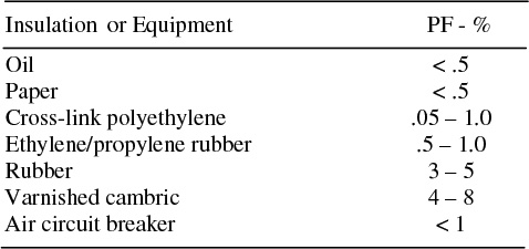
An applicable standard for testing transformers is ASTM D-924, which specifies a type of “cell” used for PF tests of the insulating oil, and gives the results expected. Good oil (e.g., new) has a test power factor of .05. Contamination by the products of deterioration (moisture, dissolved gases, carbon, etc.) will increase the power factor observed. Values above .5% and up to 2% indicate further investigation is in order. Values above 2% indicate a need to do further tests of make repairs, depending on the type of device. Table 6.3 lists typical PF values considered to be the limits for “good” insulation for various types of power equipment insulating materials.
Table 6.3 Limits for “Good” Classification of Various Insulation and Equipment Types Based on PF Test
Polarization Recovery Tests
Deterioration of cellulose insulation and insulating oil inside a transformer can reduce the time constant they exhibit for establishing a space-charge polarization across their insulation or through a sample of oil. If a DC voltage is briefly applied across insulation to build up a charge across it, and then removed, the rate at which the impressed voltage grows and/or dissipates can be tracked. The time constant of the rate of dissipation gives an indication of the quality of the insulation. It will be much shorter if the insulation has more leakage.
Thus, a test of how quickly an insulator or insulated device reacts to an applied DC (capacitive) charge applied to it (i.e., its polarization time constant), is a measure of its deteriorated or contaminated condition. Note that this test is broadly similar to the power factor test in one way: it keys on capacitive/resistive properties of the insulation to identify its strength.
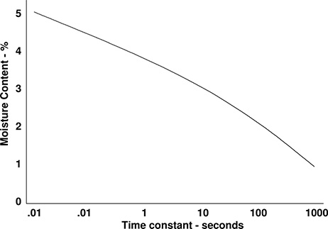
Figure 6.2 Polarization test determines a time constant of the insulation, which correlates with condition. This plot shows time constants derived from laboratory tests of oil-impregnated paper with known quantities of moisture.
Polarization recovery tests of a transformer’s winding insulation are performed on a de-energized unit. The low side windings are joined and test cables are connected to the high side terminals. A known DC voltage (e.g., 2,000 volts) is applied for a period of time that is varied (minimum and maximums are typically 1/50 to 5 seconds). By varying the time of applied voltage, the time constant associated with the polarization as it develops across the insulation can be determined (Gill, 2008). Figure 6.2 shows the results of tests on transformer-type oil-impregnated paper insulation in tests of insulation with known quantities of moisture. Testing for cables of other power equipment is similar in nature.
Hi-Potential (Hi-Pot) Tests
Transformer winding insulation strength, both turn-to-turn and phase-to-phase-to-ground, can be evaluated for leakage and possible internal faults using an hi-potential test, in which a higher than normal voltage is applied briefly to the device in order to “stress test” its insulation strength. The test can be carried out either with DC or AC voltage.
Generally, DC rather than AC hi-potential tests are used when testing cable, as DC avoids any complications due to charging capacitance. Either, or both, AC and DC may be used on transformers, the major difference in results being that the DC test tends to stress paper-cellulose insulation more and the oil less, while AC tests do just the opposite (see Table 6.2). As a rough rule of thumb, DC voltages are preferred to test lower voltage transformers, while AC voltages are used on units rated above 25 – 35 kV because DC testing might over-stress their paper insulation. Thus, the AC hi-potential test is used on most power transformers, DC on most service transformers.
In an AC test, an AC voltage at standard operating frequency but somewhat higher than the standard operating voltage is applied briefly to the transformer terminals, putting the insulation under considerable stress to test it for flaws. Application of this test varies depending on manufacturer’s recommendations and practices, the standard being followed and individual preferences that differ from utility to utility. If done as a check after maintenance, an AC voltage of about 33% (but at least 5 kV) above nominal operating voltage is applied for a period of three minutes. Slightly higher voltages might be used on new units or after a complete rebuild (acceptance tests). Higher than expected currents during this test indicate a weakness in the insulation. DC test procedures are similar in nature.
Hi-potential tests, particularly those involving AC, do put a good deal of stress on a device and fall into that category of “non-destructive” which can push a nearly failed device over the edge, discussed in Section 6.2. The very high test voltages put considerable strain on the unit and will accelerate deterioration of any incipient flaws.
Thus, high-potential voltage tests can be viewed either as an “if it can handle this it should do well in service” or as a “fail it now, not later” test. Either perspective is legitimate. For this reason, some maintenance experts (Gill, 2008) recommend against hi-potential tests as routine procedure. Instead, recommendations are usually to restrict their use to new or rebuilt equipment undergoing acceptance testing. Regardless, common sense dictates that they be applied after less stressful forms of testing a cable, device, or transformer core have been successfully passed, such as resistance and PF tests and the TTR and winding resistance tests in transformers. Those might reveal problems that hi-potential testing would worsen.
Induced Potential Test
The induced potential test can be viewed as a variation on the hi-potential test, in that it too, is a quality evaluation stress test of winding insulation. Carried out much like the hi-potential test, it is done with higher than normal operating frequencies. As with the hi-potential tests, there are slightly different forms of this test, carried out with different voltage levels and frequency. One common form involves applying twice the nominal operating voltage at 7,200 Hz for up to one minute. Others vary the voltage, frequency, and time, with lower voltages and frequencies being applied (e.g. 65% and 120 Hz).
This test puts units under considerable stress due to high voltage and high frequency (see footnote 2, earlier) and is recommended only on 5 year intervals or greater. It also must be carried out with great care to avoid creating resonance or induced voltages in other parts of the transformer and its auxiliaries.
Partial Discharge (PD) Tests
If an AC voltage is applied to a cable, it may cause a “partial discharge” inside any voids, cracks, or gas bubbles in the insulation. Generally, the volume inside the void has a lower breakdown limit than the insulation around it. Therefore, the induced voltage, if high enough, will cause this “weaker” zone to discharge without causing any discharges in “good” parts of the cable.
This partial discharge creates a small, very brief (measured in nanoseconds) electromagnetic pulse, which can be sensed by a suitable type of detector if placed on the cable. The pulse is detected by sensing it at one or both ends of the cable, and the computed time lag between pulse initiation and detection is used to determine distance from the point of measurement to the point of the defect. PD tests excite a cable using an appropriate AC voltage, and use a sensitive detector to track the pulses given off by the partial discharges. The PD test equipment analyzes the timing of both the test voltages and pulse arrival (i.e., both travel the length of the cable to the point of the flaw) to determine the location of the partial discharge. In this way, this test is similar to time domain reflectometry.
There are a host of complications to be overcome, however. The pulse, never very strong (these are only partial discharges, and relatively weak), suffers attenuation as it radiates away from its point of origin, so that the detector must be very sensitive to detect it. And, being of very short duration, the pulse is composed of all many frequencies.3 The attenuation of its radiating signal is frequency dependent. Essentially, it radiates through a filter with different amounts of attenuation in different frequency bands. Attenuation in the different bands depends on the test equipment being used, the cable type, duct types, soil, and other conditions that might influence the impedance as a function of frequency in the cable. Splices and branches along the cable also affect pulse propagation and attenuation, and may create “echo” pulses. If the neutral is badly corroded or damaged, the partial discharge will not pass down the cable. If the test is measuring a branched circuit, it becomes difficult to determine which branch a particular pulse is measuring.
These problems are solved for the most part in a wide variety of commercially available sources of PD tests. While based on this overall concept, each approach has specific characteristics designed to give advantages in some types of situations and/or to work around some of the most common problems encountered. Voltages used are generally about at the normal operating voltage or slightly higher (voltage must be high enough to excite partial discharges). Some test methods use standard frequency, others very low (.1 Hz), others high frequencies. Some use DC and then switch to AC of standard or varying frequency. Other variations include a host of novel and innovative ways to detect and measure pulse characteristics and infer location from them.
3 From a Fourier analysis standpoint: a pulse of “zero” width contains an equal amount of all frequencies. The actual pulse is so short that it has a very wide spectrum.
The wide range of characteristics involved makes it impossible to generalize about either the results or the limitations of PD methods. The amount of stress that is put on the equipment also varies greatly depending on the exact type of test procedure used. However, some PD tests, which apply an alternating voltage up to 1.5 times nominal, can put considerable stress on cables and associated equipment.
6.4 TESTS AND DIAGNOSIS OF INSULATING OIL
A major component in many electrical devices is insulating oil. It provides two functions. First, it provides dielectric strength, acting as an insulator, limiting current flow to where it is intended to flow. Secondly, it provides cooling capability, absorbing heat and transferring it away from where it is produced (e.g., a transformer core). The oil in major equipment such as oil-filled transformers, circuit breakers, and voltage regulators should be checked periodically. This can include both tests to determine that it is capable of doing its jobs (insulation and cooling), and diagnostic tests for clues to the condition of components inside the device (sludge build up, indications of arcing or overheating). Analysis of the insulating oil is one of the best condition assessment tools available for devices such as transformers.
Simple, Fast, and Reasonably Dependable Diagnostics
Tests of insulating oil are among the chief means of diagnosis for power system equipment for several reasons. First, a lot of electrical equipment contains insulating oil – it cannot be ignored and in fact should be checked, meaning that most testing has to deal with it. Secondly, such tests are performed on samples that can be drawn from the device easily without de-energizing it or making any special arrangements. Most power transformers are fitted with an oil sample valve or outlet to facilitate such testing. The equipment itself is not fitted with sensors or otherwise affected and can be left in service, a big advantage. Third, the tests are then carried out away from the device, in an non-energized (except for any test equipment) situation, which is safer and faster.
Finally, and perhaps most importantly, some types of insulating oil diagnostics (e.g., dissolved gas analysis) provide dependable diagnostic information about the severity and type of internal problems in a device. For this reason alone, tests of insulating oil are the cornerstone of condition assessment, particularly for older equipment.
Of course, oil tests and diagnostics are not enough by themselves. Oil tests do nothing to assure that other aspects of a device (bushings) are in good shape. Condition of other equipment can often be determined only by detailed exterior inspection and monitoring (for leakage in bushings, etc). But any program aimed at condition assessment of transformers and similar equipment will have to rely heavily on analysis of the insulating oil, about the only means of non-intrusively diagnosing the conditions inside the device.
Oil Samples Required
ASTM standard D923 provided a recommended standard for collection and handling samples of transformer, breaker and other power system equipment oils and is widely followed within the United States. It recommends sampling fluid from the bottom of enclosures when the fluid (oil) has a specific gravity less than
1.0 (as for most insulating oils), and from the top of the tank for those with a specific gravity above 1.0. This standard also specifies the types of materials to be used for containers and equipment (generally glass, with no rubber in the seals) and how to clean them. It gives recommendations for how much (usually 2 quarts) and under what conditions samples should be drawn (avoid humid days), and how to handle and ship samples, if needed. A good summary of this standard is included in Gill, 2008, Chapter 5 (see references).
Freeze test
A quick, inexpensive, but inexact, sample test for insulating oil is to place the oil sample in a transparent glass bottle and put it into a freezer set to slightly below 0°
C (32°F) for several hours or overnight. Water in the oil will freeze, while the oil will not. Oil with any noticeable moisture content will appear milky or foggy.
Color test
This test involves passing a light of known strength and frequency content through the oil and measuring the spectrum of transmission (amount and color of light passed). The resulting spectrum is compared to a table of known colors for new oil and known changes due to various types of contamination and/or deterioration. The color test can identify quite well the degree of carbonization from switching (tap changers, breakers, oil-filled switches), which correlates with switching operations/condition. It can simultaneously evaluate oil for a number of other conditions too, but is considered inexact, so that it is often not used if more comprehensive tests for acidity, gas, and moisture are to be done.
Water Content (Karl Fischer) Test
Water can exist in the oil inside a transformer or other device in one of three ways. First, it can be dissolved into the oil. Second, it can be emulsified; a state in which it is distributed throughout the oil as minute droplets. Third, it can pool at the bottom of the tank or device. Water has several effects, all detrimental. First, it can reduce dielectric strength. Second, it can be absorbed from the oil into paper insulation and other materials in the equipment, reducing its strengths (both mechanical and dielectric). Third, it can promote corrosion (rust) of the case and other materials.
A small amount of moisture can actually be dissolved in the oil without having a highly deleterious effect on dielectric strength. However, this amount is temperature dependent – typically oil can contain up to 20 ppm at 0°C, rising to
100 ppm at 45°C and 200 ppm at 50°C. If dissolved moisture builds up when the unit is very hot and the unit is then cooled (as could happen during high loading periods). It will then “emulsify” out as micro-droplets throughout the oil – emulsified water. Even a very small amount of emulsified water in oil will reduce its dielectric strength greatly – the tiny droplets form pathways for discharge.
Thus problems caused due to moisture in the oil often occur after the load has passed peak load period and as the oil is cooling from the temperatures reached during peak conditions, but some internal elements of the windings are still warm. Emulsified oil stays that way (unless temperature rises again and it dissolves back into the oil). Typically, it will not “demulsify” (accumulate into larger drops and fall to the bottom of the tank) but will stay mixed into the oil as micro-droplets until removed.4
Tests for water include specific gravity tests, which measure the oil’s specific gravity against that of new oil of the same type. These are non-exclusive tests for water - deviations from a typical new value of .84 may indicate something other than water is present. Worse, the presence of other contaminants (lighter than oil) can counteract the presence of water (heavier than oil) in this test.
A water content test, often called the Karl Fischer Test, can be applied. There are three ways to apply the test, but the concept in all forms is to use iodine to absorb moisture chemically, then to detect and measure its presence in the sample. These tests are inexpensive, fast, quantitative, and dependable.
Dielectric Breakdown Tests
The oil can be directly tested for insulating strength using any of several types of test procedure. Two common types defined by the American Society for Testing and Materials (ASTM) are the D877 test, often called the “cup test” or disc electrode test, and the D1816 test, and often called the VDE test. Both identify at what voltage gradient strength the oil will break down.
The D877 test is performed in the field with portable machinery and involves putting about a pint of oil in an insulated container holding two round-faced disc electrodes separated by a .1 inch gap. Voltage is then raised at a rate of 3 kV/second until breakdown occurs. The test is usually conducted on five samples. A value of 23 kV is considered satisfactory.
The D1916 test is performed in a laboratory using about a quart of fluid in a VDE cell, a type of container within which are spherically capped electrodes with a 36 mm sector diameter and 25-mm radius with a very narrow (.08 inch) gap. The oil can be circulated in the cell, simulating oil movement inside a transformer.
4 Emulsified water is best removed by vacuum dehydration. Cooling the oil will precipitate some but not all emulsified water has droplets large enough that they will drop to the bottom of the unit in all conditions (the amount of water that can emulsify in water is a function of temperature). Typically, centrifuges or filtration will not remove emulsified water. Chemical means could also be used, but most of those methods leave traces of other chemicals which are just as detrimental, if not worse.
This test is considered more sensitive to moisture in the oil, and a better indicator of electric strength as the transformer sees it, than the D877 test.
Acidity and Sludge
Oxidation of the oil (chemical breakdown/combination of the oil with oxygen) will take place anytime the oil comes in contact with air and water, both of which contain oxygen that will chemically combine with the oil to form acid; eventually this acid precipitates out as a sludge. Some materials commonly used in power equipment promote oxidation, acting as a catalyst. One is copper.
Sludge buildup not only can clog radiators but also effectively “removes” oil from the reservoir, reducing the net amount available for cooling. Thus, most transformers are sealed to limit the amount of oxygen (air and moisture) that can get inside the unit. Sludge will stick to internal surfaces of a device, not necessarily accumulate on the bottom of the oil container. Inside a transformer it will coat the core, cooling ducts, and radiator lines, thereby reducing thermal transfer capability and resulting in more rapid and higher heat rise during peak operation. A transformer or breaker with indications of sludge buildup should be given priority for removal of sludge. The sludge can be removed by treating/filtering the oil (slow, uncertain) or by circulating hot, new oil to remove it. Regardless, heavy sludging leads to failure.
Oxidation is accelerated by temperature. A rough rule of thumb is that the rate of oxidation doubles for every 18°F (10°C) rise in temperature. Therefore, overloading a transformer can greatly affect the rate of acid formation. Tests have indicated that acidity is proportional to the oxygen absorbed in the oil.
Generally, insulating oils used in power equipment have “antioxidation” compounds such as DBPC (2.6 di-tert-butyl persesol) added to them to prevent acid formation. These act as “sacrificial” oxidation targets, chemically combining with oxygen to remove it before it can attack the oil itself. Oxidation of the oil begins when these materials are completely consumed.
Acidity tests
There are two ASTM laboratory tests (D974 and D664) and one field test (D 1534) for acidity of oil, all of which determine a “neutralization number” which is the number of milligrams of potassium hydroxide required to neutralize the acid (return it to neutral pH) in 1 gram of fluid. A test value of .4 or less is considered acceptable. Values above 1.0 indicate severe problems. The D1534 field test involves drawing out small samples of the insulating oil and adding it to a “wash solution” already contained in a small glass cylinder. Pre-packaged, sealed small “doses” of KOH (potassium hydroxide) are then added and their number counted. The wash solution has a color-changing property (like litmus paper) – it turns pink when one too many vials of KOH have been added.
Interfacial tension tests
An interfacial tension test can determine if the acid accumulation has or is leading to accumulation of sludge. Acid buildup in an oil leads to sludging, but as shown in Figure 6.3, the latter may follow the other by a good deal of time, and acid alone is not an indication of the presence of sludge.
Interfacial tension tests (IFT), such as ASTM D971 and ASTM D2285 measure the sludging characteristics of the oil and give some indication of the amount of build up. These test for sludge implicitly, but measure the tension between oil and water (i.e., akin to the surface tension between liquid and air). Interfacial tension between the two is reduced by the presence of “polar molecules” (sludge) in the oil. A reading of less than 15 dynes/cm is indicative of sludge buildup (a good reading is 22 dynes/cm).
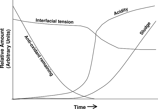
Figure 6.3 Relative rates of antioxidant consumption, acid accumulation, and sludge accumulation, and the resulting change in interfacial tension in one transformer test. A drop in interfacial tension signals that acidity is already increasing in the oil, but is usually a precursor to, rather than an indicator of, sludge formation.
Analyzing Gases Produced by Insulation Deterioration
The different processes of deterioration or damage occurring inside a transformer or other oil-filled device create various gases, such as CO2, acetylene, hydrogen, and methane, which dissolve into the oil or pool in the space above the oil. While dissolved gases can affect the properties of the oil, the primary reason to test for the amount and type of dissolved gases in oil is that they give an excellent indication of the type and state of deterioration taking place inside the device.
The chief cause of gas being generated inside a transformer is from deterioration of the paper-cellulose and oil insulation - deterioration that is greatly exacerbated by heating. Deterioration rates are an exponential function of temperature. Deterioration-to-failure times for “cold units” are often measured in centuries, but lifetime at full load might be only a few years.
Cellulose (paper) insulation overheated to 150°C or above begins a breakdown process that produces carbon monoxide (CO), carbon dioxide (CO2), traces of hydrogen (H2) and methane (CH4), and water (H2O). The presence of ethylene (C2H4) or ethane (C2H6) indicates the oil has been heated to temperatures close to its absolute physical limit of around 550-600°C. Acetylene (C2H2) indicates the oil has been heated to even higher temperatures, usually by electrical arcs passing through it (very bad in a transformer, not so bad in a circuit breaker). Thus, the type and amounts of gas present give an indication of both the amount and cause of deterioration or damage that have occurred inside the device.
Total combustible gas test
For the most part, the gases produced by deterioration and damage (except for water vapor and CO2) are combustible: they will freely combine with oxygen in the presence of a flame or sufficiently high temperatures. Total combustible gas analysis (TCGA) measures the amount of these gases by drawing off some of the gas from the space above the oil in a transformer and measuring what portion of the gas sample burns. Such tests can only be performed on sealed transformers which have a nitrogen blanket (nitrogen filled space) or conservator system, but this includes most types of power transformers. Many power transformers are fitted with a gas-sampling line or an external valve to facilitate such tests. Total combustible gas analysis tests can be performed in the field with a portable unit. These units use a catalytic burner and a Wheatstone Bridge circuit to measure resistivity. The burning of the gases causes changes in the resistance of one element of the circuit, which is detected and correlated with the amount of gas. These tests are quick, inexpensive and precise as to total amount of gas, but non-specific as to the type of gas, and hence the exact nature of the problem. However, large amounts of combustible gases clearly indicate a problem.
Dissolved gas tests
Dissolved Gas Analysis (DGA – Dissolved Gas Analysis) is done in a laboratory and will identify exactly what and how much of each type of gas is present. They are done not from a sample of the top-oil gas, but from a sample of the oil itself. A vacuum pump is used to extract the dissolved gas from an oil sample and pass it to a gas chromatograph. The quantity of each type of gas is then determined by gas chromatography. This gives a better indication than TCGA of both the amounts of deterioration and the type and cause of it.
Use of insulating oil tests
The presence of CO, CO2, and water alone, determined by a DGA test, indicates operation at high but not necessarily undue temperatures, and what might be called standard deterioration – aging with time in service. Sound transformers running at peak loading typically generate small but measurable quantities of these gases. However, traces of the other gases, ethylene, ethane, and methane, indicate problems (non-standard deterioration) and give an indication that the equipment is not a sound unit.
However, the most commonly used gas test is the total combustible gas analysis (TCGA), because it is quick and can be performed in the field. It does not provide accurate data on which gases are present and in what amounts, and so cannot provide the information needed to determine the cause of any problems detected directly. However, by doing TCGA analysis frequently (it is a very inexpensive test) the rate of increase of these gases can be tracked, and that rate is useful in distinguishing among the different gassing causes. Creation of gases from deterioration of paper insulation, even if at very high “normal temperatures” is a very gradual process. A high measurement might mean only that the unit is old and has not been tested/purged in the past. Subsequent tests several months later might reveal a low gassing rate and thus indicate this is the cause. By contrast, impending-failure conditions that are caused by the very high temperatures generated by short circuits or by arcing through the oil create gas at a much higher rate. A high rate of increase over a short period of time (a day in the case of a unit thought to be in jeopardy, a quarter year otherwise) can provide a good clue as to the cause of the gassing: slow – normal deterioration; fast – an internal problem possibly indicating imminent failure.
How the Test is Carried Out is Important
It is important to bear in mind that the cost, time and resources required, as well as the sensitivity and quality of results obtained will depend greatly on both the exact nature of the equipment being used and the procedure for its application. This means keeping in mind what is grounded and what is not, measurements of equipment temperature before and after, etc. Similarly, the level of stress put on the equipment can depend on instructions being followed precisely and how the test was applied.
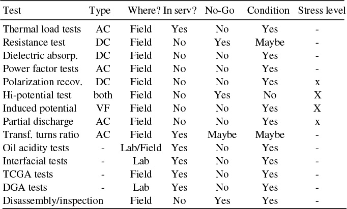
Table 6.4 Power System Electrical Test Procedures
Comparison of Tests and Diagnostic Methods
Table 6.4 compares the various test procedures for equipment and oil on the basis of various characteristics. From left to right, column one describes the type of test, column two the type of voltage used (AC, DC, or VF for non-standard or variable frequency), and column three identifies whether it is performed in the field or laboratory. Column four tells whether the unit can be left in service or must be de-energized while the test is being run. Column Five identifies whether the test is typically used as a “Go/No-Go test” - one that provides a definite indication that the unit is unfit for continued service. Column six (conditions) explains whether the test provides relative diagnostics on condition and deterioration that can be tracked over time. Finally, column seven gives the level of stress caused by the test, the size of the X indicating relative level of equipment stress caused by the testing.
6.5 ON LINE AND REAL-TIME MONITORING AND TESTING
Any test that can be performed on an as-needed basis in the field can be performed on a continuous and ongoing basis by equipment installed to test and remotely report the test data. Whether such online or real-time testing is justifiable from a benefit, cost, and operational basis is another matter entirely. It is technically feasible, and in the case of most types of tests, equipment is available or can be assembled to do so when needed. Online means the data is sent back remotely but perhaps not instantly: the maximum temperature seen during yesterday’s 24 hours, etc. Real-time means the data is sent nearly instantly, with no delay except that very slight time required to assimilate and transmit the data.
Online Monitoring versus Testing
A distinction should be made between online and real-time monitoring of equipment and testing. Monitoring is the remote measurement and reporting of data relevant to its function and operation. Current, voltage, and power factor measured at a power transformer or through a metering point provide data needed to observe how the equipment is operating and make good decisions as to the continued operation of that equipment. For example, temperature is often monitored in a transformer and used for operational decisions on loading. Similarly, breakers and switches might be monitored to verify their position (open, closed, breaker recharged and ready to operate, etc.), and voltage regulators, load tap changers, or switched-bank capacitors monitored as to position, etc. Testing is remote measurement and reporting of data specific to the diagnosis of the condition or status of the equipment. For example, online reporting of the TDG (total dissolved gas) amount in a power transformer provides nothing useful to operators of the system, other than an indication that the unit might be at jeopardy of failing. However, a watchful eye on the total over time will provide good information about the general condition of the unit. Similarly, remote collection of information on the timing of each breaker operation or close can give an indication of the condition of the breaker itself. That information will be of very limited use to operators of the system but can be used to diagnose condition and if and when units need maintenance. Self-diagnosis and incipient failure diagnosis involves local collation and analysis of test results and operation monitoring data to determine testing and diagnosis results which are then transmitted. A system might analyze DGA readings on a transformer as well as acoustic and radio-frequency monitoring of noise, along with temperature, and deduce that the unit was suddenly changing condition rapidly and/or approaching a boundary or pattern for one of more of these readings that indicates concern. An alarm, perhaps in conjunction with all the readings, would be sent. This local analysis might be done by a unit attached to and at the equipment, or a local hub, for example one system that analyzes all four power transformers at a major substation.
A Slow and Long Term Trend Toward More Online Testing
Remote online or real-time reporting of TDG readings and switch operating times is technically feasible and equipment is available (much of it based on methods and equipment originally developed for military applications). But it is seldom used, because it is often not cost justifiable. At many utilities, benefit/cost analysis of online TDG readings shows it will provide little additional benefit beyond that derived from routine manual testing, and at a higher cost. Breaker and other equipment testing via remote collection is similarly not justifiable. That said, three trends will all lead to a gradual increase in the amount of online/real-time testing done remotely.
1) The benefit derived from online testing will gradually improve. As summarized in Chapter 1, the problems caused by aging equipment do not increase dramatically and quickly, but instead slowly but steadily over the long run. Sound management will mean a good deal of old equipment will always remain in systems. Therefore, in the long run, the value seen from online test result reporting will gradually increase – perhaps to two or three times that at present.
2) Cost will drop for the sensors, data systems and hub receiving systems, and analysis and tracking software. There is no reason to think that this will not also be a gradual but steady trend in the reduction of the price of equipment and support software for such applications, along the lines typical in any field of electronics.
3) High rates of automation and smart systems will reduce the marginal cost of adding testing. Finally, Smart Grid systems will result in a nearly omnipresent data communications grid, meaning that the cost of adding testing to the current system will be small compared to the cost of creating the system for that purpose today.
That said, the authors do not anticipate anything other than a very slow move toward online testing and self-diagnosis for equipment. This will occur in a top down manner, with major units such as large auto-transformers and key chock points for system security receiving comprehensive online testing and real-time incipient failure coverage first, with the system gradually deploying to equipment of lesser criticality.
Smart Grid Automated Testing
One key performance goal for many Smart Grid distribution systems is a “self-healing” feature. When breakdowns or failures occur the system will re-configure its switching to isolate failed equipment and connect sections of the system isolated by the failure to a still-working source of power. This is done in a manner that causes the least possible interruption to customer service.
Currently, most self-healing system plans and concepts envision the self-healing capability as only reactionary – the smart equipment waits until a failure has occurred to take action. A potential improvement would be a Smart Grid proactive self-healing capability. This would use automated and remote testing of key equipment to determine where and when it is likely that an equipment breakdown or failure is likely to occur. Switching would then re-configure the network to isolate and deactivate that equipment, avoiding the failure in a way that would eliminate or mitigate service interruptions to customers.
Such pro-active systems will very likely be deployed eventually, at least in places where the value they provide in increased reliability of reduced equipment damage justifies their addition. However, considerable progress needs to be made in the durability and dependability of automatic remote testing sensors, and in the cost of such units, and in evolving central or peer-to-peer control systems to properly handle the outages.
Therefore, it will be the reactionary self-healing systems that drive deployment of Smart Grid self-healing capabilities. A consequence is that their deployment will create a lower marginal cost for the addition of automated remote testing and pro-active self-healing capabilities. The authors expect that while self-healing capabilities will make their way quickly into distribution systems in most first-world countries, pro-active capabilities will deploy much later, and much more slowly.
6.6 SUMMARY AND FINAL COMMENTS
This chapter summarized inspection, testing, and diagnostic procedures for power system equipment. The major goal of these activities, as it relates to aging infrastructure, is to determine the condition of power system equipment already in the field. Properly carried out, such inspections and tests can identify if that equipment is “good to go” for service and give some estimate of remaining service lifetime. They also catch some failures before they occur, permitting the utility to make repairs, saving equipment that might otherwise be ruined.
While this “ounce of prevention” function is worthwhile in reducing equipment replacement costs by saving some equipment from failure, the real value of inspection, testing, and maintenance is its ability to reduce the number of outages that occur in service. It is worth considering that exact knowledge of when a unit would fail would be worth a great deal to a utility, allowing it to schedule replacement, but at exactly the latest moment possible. While even the best of condition-assessment methods can not exactly determine expected lifetime, the information provided is a step in the right direction and worth a good deal toward improving service quality and allowing optimal management of equipment lifetimes.
The methods covered in this chapter are worthwhile only if applied in well-managed program aimed at improving and maintaining service quality at high levels while keeping costs as low as possible. Chapter 9 will discuss application of these methods to power system equipment and identify how the tests are best organized and used in an inspection and test program. Chapter 10 will discuss prioritization methods for O&M, and how utilization of units can be optimized so the utility gets the most overall “bang for the buck.”
REFERENCES AND BIBLIOGRAPHY
J. J. Burke, Power Distribution Engineering – Fundamentals and Applications, Marcel Dekker, New York, 1994.
P. Gill, Electrical Power Equipment Maintenance and Testing – Second Edition, CRC Press, Boca Raton, New York, 2008.
H. H. Malik, A. A. Al-Arainy, and M. I. Qureshi, Electrical Insulation in Power Systems, Marcel Dekker, 1998.
O. C. Seevers, Management of Transmission and Distribution Systems, Fairmont Press, Lilburn, 1995.
W. A. Thue, Electrical Power Cable Engineering –Third Edition, CRC Press, Boca Raton, 2012.