
13 Planning Methods for Aging T&D Infrastructures
13.1 INTRODUCTION
This chapter provides a one-chapter summary of power delivery system planning and the methods and processes used, with a focus on how this planning is made to encompass and focus on aging infrastructure needs. Readers who want more detail than provided here about planning in general can consult Willis (2004). More detail on the methodology for planning of aging infrastructure will be presented in subsequent chapters and in case studies given there and in the Appendices.
Power system planning involves identification of the best equipment to be added, and changes to be made, to the system. It produces specifications and authorization that identify the additions and changes, their locations, manner of interconnection to the system, and schedule of deployment.
Traditionally, system planning was oriented around expansion planning. The utility’s customer base and load were growing. At some point in the future, the present system would prove inadequate to serve the growing electric demand. When would that be? What additions would need to be made so the system would continue to be adequate? That was the traditional power delivery planning paradigm.
A consideration for aging equipment and infrastructures needs to be added. Equipment that has long been dependable is wearing out. Circuit configurations and facility locations picked decades ago may not be best for today’s and the future’s needs. need to be added into the plan to best accommodate these considerations, and mixed with those additions needed to support growth, so that the overall plan is the best – whatever best means. Since cost is an important attribute in power planning, almost invariably one of the planner’s chief goals is to minimize overall cost of handling the growth and the aging.
Aging T&D Infrastructures → Reliability Optimization
The primary negative effect created by aging T&D infrastructures is poor customer service reliability. All of the other impacts, which boil down to higher costs in one way or another, stem from the utility’s attempts to control the situation with regard to equipment breakdowns, safety, and dependability, or to improve reliability in the face of increasing equipment failure rates. Thus, “Planning for Aging Infrastructures” needs to consider operating costs and risk, and reliability and optimizing reliability gained per dollar, tailoring that reliability of service to consumer needs and utility targets.
Long Term Strategy and Value, But Not Long Term-Planning
It takes decades for an infrastructure to deteriorate to the point that aging effects seriously inhibit performance. The monies required for any viable solution are very large and must be spread over many years. Only programs that are basically continuous in nature can economically address the issues. Thus, a long-term view of the problem and its solutions is needed in order to develop a workable and affordable plan.
This means that at some place in the utility, long-term assessment and planning for aging equipment and infrastructures must take place. A utility must understand its present situation, where aging trends are taking its equipment fleet, and what it can expect from various strategies and approaches it can apply. Ideally, it will develop an overall strategy for when, where, how, and why it will address aging infrastructures and the issues they cause.
But this does not mean that all T&D planning need be done with a long-range perspective. Much of the planning at any utility is short-range – two to five years ahead, oriented, but despite that short-range plans and projects are made to fit within long-term strategy. Traditionally, such short-range planning was coordinated with long-term system and business strategy and needs via criteria and guideline formulae. For example, utilities make minimization of losses cost a long-term goal, specifically aimed at making the lifetime cost minimum. This is accomplished in planning which may look only two to five years ahead, by setting the coefficients of formulae used to compute lifetime losses costs as used in the final evaluation of options from a present worth standpoint.
Conceptually, the same criteria and formulae-based approach is used with respect to aging infrastructures (Figure 13.1).
• Corporate strategic long-range planning of and for aging is based on projection of current trends and corporate goals, eventually leading to an overall strategy and plan. This is generally a business-oriented plan but it provides budgets and metrics (for age, condition, etc.) that can be mapped to system and equipment needs. Examples will be given in subsequent chapters.
• Power delivery planners, working with the corporate planners, develop appropriate criteria, targets, and formula, that position cost and value computations and planning goals in short-range planning toward fitting the aging-related plan.
• These are then applied routinely in the short-range planning process. The result is that short-range plans developed in the two- to five-year ahead process will fall in line with both long-range needs and long-term strategy.

Figure 13.1 A utility’s long-range aging-infrastructure priorities are met by the short-range planning process by orienting it to a set of criteria, formulae, and guidelines determined from a long-range plan based upon the utility’s aging infrastructure strategy.
At times, the utility may need a special, initial planning effort leading to a program that initiates aging-related programs to get its effort “off the ground” so to speak – something that is basically making up for not having the three steps above for the past decades. This, too, will be discussed in subsequent chapters.
This chapter begins with a look at the basic purposes of planning and the five steps of the planning process (Section 13.2) reviewing the most common pitfalls in each. The purpose of short-range and long-range planning and how they interrelate to aging infrastructures is then discussed in Section 13.3. Section 13.4 then looks at the T&D planning process as implemented in most modern utilities, again emphasizing aspects that particularly interact with the aging infrastructure issues. Section 13.5 stresses the importance of the systems approach in all planning for aging T&D systems. Finally, Section 13.6 summarizes key points with respect to aging infrastructure system planning.
13.2 PLANNING: FINDING THE BEST ALTERNATIVE
What is the Mission?
Planning is a decision-making process that seeks to identify the available options and determine which is the best for the situation at hand. Its purpose is to determine the best schedule of future resources and actions to achieve a company’s, an individual’s, or an organization’s goals with respect to power. Usually, among the major concerns of planning are financial considerations - minimize cost, maximize profit, or some similar goal. In addition, service quality and reliability are almost always considerations. And often, other criteria are important, including environmental impact, public image, and a host of factors that a utility, energy services company, or energy consumer must weigh in making a selection regarding power supply. But regardless, planning is the process of identifying alternatives and selecting the best from among them.
Before beginning the planning step, it is best for a utility to review its mission statement – its overall definition of what guiding purpose and value-system defines its goals. This is particularly true with respect to meeting the challenge of aging infrastructures. Dealing with aging infrastructures, and getting what is desired in the outcome, means having focus and being realistic about constraints, goals, and capabilities. The mission statement is a good place to start. Given the realities of the situation, the aging system, a limited budget, regulatory pressures, is the current mission statement realistic? Making sure that the company’s mission statement matches both what it wants to do, now that it has assessed its aging infrastructure problem, and making sure that those principles are realistic and feasible, are big steps toward success.
A company’s “Mission Statement” succinctly defines the overall corporate objectives, while its economic goals explain its financial priorities. Usually, mission and financial goals have been incorporated in the economic guidelines and design procedures that the planner applies in his work. Regardless, while mission statements are often taken lightly by some employees, a review of the company’s mission and financial goals provides the planner with strategic insight into its planning guidelines and economic evaluation formula. Table 13.1 lists the mission statements from four large metropolitan electric distribution utilities in the United States. Planning goals for T&D, for DSM, for IRP, will be different among these utilities, because they have different priorities for what their executive management wants to accomplish. How the aging infrastructure problem will be handled in each utility and the priorities the utility puts of various approaches and solutions should be different as a result.
Mission statements are qualitative assertions of the overall philosophies and goals that lead to the quantitative engineering and economic criteria used in distribution planning. By understanding what their company is trying to do, the T&D planners have a better understanding of how to achieve those goals.
Table 13.1 Mission Statements of Four Electric Utilities
|
Planning: A Six-Step Process
Planning is a process of determining the best course of action or schedule of commitments that can be made to achieve one’s goals. The modern power delivery planning process can be segmented into the six steps shown in Figure 13.2. Each one is an important part of the process for planning in any type of industry, but in particularly utility T&D planning.
Any of the six steps, poorly performed, can lead to poor decisions, a poor plan, and ultimately failure to attain those goals. Mistakes and lack of focus in any step will lead planners astray, although the types of mistakes that result will differ, depending which one of the five was the first misstep. Below, each of the five steps is described, along with a brief summary of the goals for this step and pitfalls to be avoided in each. A lengthier discussion, with examples, can be found in Willis (2004).

Figure 13.2 Planning involves the six steps shown. See text for details.
Step 1: Identify the Scope of the Problem
Before beginning their work, every group of planners should identify their goal – exactly what they are trying to do. It is recommended that the planning problem and scope be formally written, as “this project involves planning of short- and long-term electric supply for all 821 homes planned for the new West Oaks subdivision.” This written definition of the scope defines the extent of the problem to be solved. All subsequent parts of the planning process should focus on that, and not stray (as some planners are often wont to do) to solve other problems or work in other areas. Trying to resolve a wide range of other problems in the nearby area at the same time this goal is achieved is not part of this project.
Step 2: Identify the Goals
A common mistake made by many planners is to begin their activity without specifying the goals for the particular planning situation at hand, or identifying how these goals might have changed from prior planning situations. It may be one thing to identify the problem, but the goals must explain in detail how to identify what the planners need to accomplish.
Goal definitions are quite different than mission statements. A mission statement lays out an organization’s direction, principles, and values. A goal defines explicitly what is desired to be accomplished in some situation. The former is strategic, the latter tactical. Time devoted to framing the planning situation at hand and explicitly defining the goal for it will be time well spent.
Again, as was the case with scope statement, it is best to produce a formal, written definition. This might read something like: “The goal is to develop a plan, able to be implemented within two years, which identifies all required equipment, labor, permits, and other expenses for electric facilities. This will provide the lowest long-term cost when evaluated on a present worth basis, and provide West Oaks subdivision with expected SAIDI and SAIFI of 2.0 hours and 1.25 events respectively, with all system factors meeting company standards.”
Aging Infrastructure Situations Often Encounter Severe Environmental and “Urban Fit” Constraints
Very often, particularly when dealing with aging infrastructure problems in the interior of older metropolitan areas, there are additional goals unique to a particular plan or situation. For example, it might be important to accommodate the esthetic and land-use preferences of local community leaders, or to use equipment or rights-of-way and sites already in inventory. Or, most often, a key requirement is to not require any new sites, rights of way, or visible disruption of an already crowded urban landscape. Some goals are unique to each particular case, created by an unusual situation or set of circumstances. Table 13.2 lists a number of special goals that are not uncommon to encounter when planning for an aging T&D system.
Table 13.2 Examples of Special Planning Goals or Criteria Often Encountered When Dealing with Aging T&D Systems
Fit within a specific budget. The utility may have a particular amount of money designated for aging infrastructure improvements. This money must be spent in an optimal manner, but further funds will not be available. Budget-constraining techniques (see Chapter 5) are often helpful in this situation. Substation improvements must be accommodated within existing sites. The utility either cannot obtain, or management does not want to endure the political hassle, uncertainty, and cost of trying to gain more real estate at existing substation sites. As a result, innovative ways of cramming more capacity and more complex configurations into an existing, already-crowded site, such as use of GIS equipment, compact line designs, and small-footprint transformers, must be found. No new substation sites and rights of way. This is occasionally a goal of management – to minimize the number of new substation sites, ideally to zero. New sites are expensive, subject to political and regulatory hurdles that make approval uncertain, and often create adversarial relationships within the community, which management judges it is best to avoid “at any cost.” Lack of new sites does not cause a capacity limitation issue (lack of new room at existing sites does). It causes a problem with economic and capacity reach issues of the feeder system. So called long-reach planning techniques as discussed in Willis (2004). Expansion plan must include “targeted DG and DSM or renewable energy sources of power.” Regulator or community leaders may demand that any solutions include the use of modern technologies as a means to cut T&D capacity needs, including load reduction methods and on-site generation. Integrated resource T&D planning and DG planning methods are often needed in these situations. Planners should recognize that while these special resources may provide only a small amount of relief from the reliability of service and capacity challenges of the area, they should be used to their fullest, and that they are required and in a larger sense to address societal expectations and political needs that the company cannot ignore. High reliability is required to a specific site or customer. A special customer or site may need extraordinary reliability of service even if the neighborhood around it need only be given the average level of service for the rest of the system. Examples are a professional sports stadium, a hospital, or a police or fire division headquarters located in an older area of the city. |
Step 3: Identify the Alternatives
This third step is often the most critical part of planning. This is identifying what could be done - all the alternatives open to the planner. What options are available? What variations on these options would be possible? This function encompasses determining the range of possibilities for solving the problem.
This is where the majority of great “planning disasters” occurs - the mistakes that lead, weeks later, to statements like, “Why didn’t we think of that?” For, while apparently the least challenging part of planning, a good deal of skill, breadth of thinking, and time, are required to identify the range of possibilities. Time and resources are always limited, and the temptation is strong to assume that one can see all the options just by “a quick look at the problem.” But this is seldom the case. A brilliant solution to an unusual problem most often comes from recognizing that there are also unusual options available to solve it.
The downfall of planners: failing to consider all the alternatives
The discussion of Step 2, above, mentioned that planning power delivery systems in older areas of a system can be a challenge, with locally unique challenges in many unique situations. That makes Step 3 particularly important: often viable alternatives are not obvious. Common fixes used in most situations (run a new circuit) are not possible or preferable. Uncommon approaches might be possible (the neighborhood contains many old but structurally sound buildings: a new substation can be put inside the façade of one, or a new façade that looks old, leaving the neighborhood’s appearance unaltered from the street.1
This step is often where a surprising number of computerized “automated planning procedures” and tightly prescribed template-based planned methods let their users down. When looking at or reviewing their planning procedure, electric system planners should study if and how it assures them that it does consider all possible options. Just as planners need to remind themselves constantly to be open-minded, and not to have pre-conceived notions about where the solution lies, they need to assure that computer programs and processes they use are also not limiting their identification of the full range of options. In general, it is recommended that planning in older areas in the interior of major metropolitan areas be treated as a special situation, with a team of at least two planners. The team requires both innovation and a lack of adherence to traditional thinking, and above average consideration of those things that only come with years of experience. Often, what works best is a team composed of a younger planner with an innovative attitude and a very experienced old hand whose personalities mesh well.
1 The authors used this approach when working together in the late 1990s, on the upgrading of T&D capability in an aging area of a major American city. To this day most people walking past on the sidewalk are unaware they are passing a five-transformer, 200+ MVA power substation that feeds one-fifth of the entire downtown area.
A common failing: too short a planning horizon
Beyond a team that will be a bit more innovative than usual and is more savvy than needed in the typically suburban planning situation, another requirement for success in most aging infrastructure areas is a longer planning horizon. Simply put, the system did not get into its current dilemma in a short period of time and a successful plan is going to be one that rights its wrongs quickly and permanently. Managers should require that, in addition to a short-range plan that fixes immediate issues and priorities, the team have an overview of what is required and how the long-term issue will be dealt with. Such a longer range vision often provides insight and help to the short range planning, but will be neglected by planners in the interests of urgent short-term priorities, unless they are explicitly told they have both the time and resources to delve into the longer range
Failing to look far enough ahead often limits the available options by default, contributing to poor planning. A common lament among T&D planners at some utilities is, “We could have done a much better job, but the good sites and land were already taken.” What is usually left out of this complaint is that the planning period used for distribution expansion evaluation was only three to four years ahead. The utility is losing out to other people interested in acquiring sites for other purposes, people who are looking ahead more than three or four years.
By looking only a few years ahead, the utility reduces the number of options available to it. In addition, planners often fail to see the consequences of long term growth and change. If the area has the possible potential to redevelop into significantly more load, then eventually it will redevelop, and the existing system, aged as it may be, will have to be bolstered. The question, then, is not if, but when is that potential redevelopment soon enough to affect elements and economies of today’s short-range plan?2
Having a sufficiently long planning period does not in and of itself assure good planning, but it is a necessary first move in that direction, particularly in difficult situations such as those commonly encountered in long-developed areas with aging infrastructures. For distribution planning, a minimum planning period of five to seven years is normally recommended, and in aging areas, a horizon at least 20 years old. Long range plans do not need to be developed with great specificity (nothing 15 years out is going to be built for a long time, and conditions might change). But they do need to be developed to the point that plan ners can answer the question: “Where are we going over the long run?”
2 Anyone who thinks that a blighted, older area of a city can be beyond redemption and will forever remain an older, sleepy area should consider the history of the inner harbor area of Baltimore.
“Do nothing” should always be one of the alternatives considered
One of the most serious mistakes made by planners is to assume that something must be done. Occasionally, it is both less expensive and better from a service standpoint to delay any commitment or change to the electric system - to do nothing. Even when this is not the case, “nothing” should always be included in a planning report as one of the reviewed options. This permits the planners to explicitly identify why something must be done, by showing that “doing nothing” would violate criteria or requirements, or lead to very poor economy.3 Evaluation of “nothing” is a key element of justifying a plan’s recommendations.
Step 4: Evaluating the Alternatives
All alternatives should be evaluated against a common and comprehensive evaluation standard, one that considers every aspect pertinent to any option, and one that addresses all the goals. For power delivery planning this means evaluating alternatives against criteria and attributes that represent the utility’s requirements, standards and constraints. For DSM programs this means matching customer needs with marketing standards and guidelines.
Very often, the actual planning process will combine the evaluation and selection functions in a process designed to reject alternatives quickly and with minimum effort. Regardless, all alternatives should be evaluated completely with respect to everything that bears on the problem at hand. Planning methods should be examined carefully to make certain that they, too, like the various alternatives being considered, are complete.
Alternatives must be evaluated against both criteria and attributes. Criteria are requirements and constraints the plan must meet, including: voltage, flicker, other service standards, contingency rules, loading limits, safety and protection standards, and so forth. Such criteria only have to be satisfied: if standards allow voltages down to .95 per unit, then a design alternative is acceptable if it has voltages of .95 per unit, but no lower. On the other hand, attributes are values for which the planners wish to achieve the best performance possible: an attribute is a quality that is to be minimized (or maximized) while still meeting all criteria. One attribute in nearly all electric supply planning is cost. And while voltage drop, protection coordination, and other requirements are quantities that the planners would like to see exceed standards by comfortable margins, they should be treated as the criteria they are: good enough is good enough.
Traditional power delivery planning is single attribute planning, in that only the one attribute (cost) is to be minimized. This third step, evaluation, rejects the alternatives that do not meet all criteria and passed all the others. Among those left, the minimum cost alternative can be selected (in Step 5). Cost is a multi-faceted attribute, all aspects of which must be included in the evaluation: equipment, site costs, taxes, operations and maintenance, and losses. Table 13.3 lists some of the more common criteria and cost factors that need to be assessed in electric supply evaluation at the distribution level.
3 A common argument against this approach is that evaluation of “do nothing” is not needed because the answer is so obvious that it does not need to be included. But if that is the case, it is simple to do, so why not include it and document its evaluation?
Table 13.3 Some Typical Criteria and Costs Evaluated in Electric System Planning

Where mistakes occur in the evaluation step
Mistakes that take place in the evaluation function generally occur because the planners do not check to see if their methodology meets three requirements:
1. It considers all criteria and factors that are important to the goals. For example, if a goal is to achieve a certain level of expected reliability, then the planning methods need to be able to assess reliability of all plans on an equivalent basis.
2. It must evaluate all criteria fully with respect to all resources. For example, some planning methods evaluate reliability only with respect to outages and connectivity. When evaluating DG and DS, the reliability method must analyze and accommodate lack of fuel availability and potential for failure of the units themselves.
3. It treats all options equitably. For example, if planners include the cost of oil spill containment and fire prevention equipment when evaluating T&D alternatives that include oil-filled transformers, they should provide like detail in the assessment of the DG alternatives.
Step 5: Selecting the Best Alternative
In many planning procedures, this function is combined with the evaluation function, and it is difficult to identify where evaluation ends and selection begins. In fact, efficient computerized planning methods that help planning engineers minimize the time and effort required to complete the planning process tend to combine Steps 3 through 5 into one process. But regardless, if the most important point in the identification-evaluation/selection process is the definition of “best,” it must match the goals and value system being used. The evaluation/selection method being used must mirror the desires of the organization, and be capable of distinguishing between alternatives in a valid manner in these areas.
A surprising number of planning mistakes, or inefficiencies, occur in the final selection process, because the planners do not assess alternatives on the basis of what is truly important to their goals. A planning method’s selection function should be examined to determine that it:
• Uses the definition of “best” that matches the planning goals. The fact that alternatives were evaluated on the basis of a particular attribute in Step 4 does not mean that it is weighted properly in the selection phase. For example, a common failure in T&D planning is to assess the value of electric losses in a distribution plan, but then fail to acknowledge their value in selecting the best design.
• Can accurately distinguish between alternatives. What are the limits of accuracy of the planning process? If it is only accurate to within 3%, then selection of a “best” alternative on the basis of its being 1% better than another is questionable. Error range in the evaluation and selection among close cases must be small enough to assure that the determination of “which is best” is accurate.
Many computerized planning procedures produce only approximate evaluations. Planners often fail to consider these limitations and interpret minor differences in computed evaluations as significant, when they are not.
Step 6: Being a Proponent of the Plan
This step is in many ways the key to success in the 21st century utility industry. Plans have to be sold to executive management, to stakeholders including in some cases stockholders, and in all cases, community and regulatory leaders. The planner is often heavily involved in this process and sometimes asked to lead it.
There are several critical points to keep in mind about this step. First, this represents a major change in perspective for the planners. In Steps one through Five, objectivity was a key. Make certain all options are considered on an equivalent and balanced basis to evaluate and report fully and fairly.
Once management’s approval process has selected of an alternative, the planner’s job changes. The planner, whose job was to objectively present the alternatives and their evaluation to management, now becomes a proponent whose job is to help sell that plan to all stakeholders. This can be a challenge, because management may have picked an alternative other than what the planner believed was best. Despite this, the planner’s job is to fully support carrying this option forward as the plan, helping sell it to all other stakeholders, and guide it through the regulatory approval process, until it is handed off as a fully authorized project to be built.
This job is easiest if the preceding five steps were well structured within a fully documented and institutionalized framework, used a credible planning method at every step, and was transparently and traceably documented throughout. Defensibility is often the most important element of a good plan.
13.3 SHORT- AND LONG-RANGE PLANNING
Lead time - the time it takes to prepare, build, and install facilities - sets the minimum planning period for any endeavor. If it takes up to five years to order materials, obtain permits, survey, build, test, and put into service a new substation in the core of a major metropolitan area, then the power distribution utility has no choice but to plan at least five years ahead in order to make certain it will have all new substations by the time they are needed.
Thus, the minimum possible planning horizon is a function of the lead time required to put solutions into place. Lead time varies depending on the type of equipment, the level of the system, and the local planning approval process for electrical facilities, and other aspects of the situation. Table 13.4 gives some typical lead times by “level of the system.”
Short-Range Planning: Decisions and Commitments
The purpose of electric utility short-range planning is to make certain that the system can continue to serve customer load while meeting all standards and criteria. This stage of planning is driven by the lead time - by the fact that it takes time to get things done and that decisions must be made ahead of this lead time.
Short-range planning must identify the commitments and purchases that must to be made today in order to allow them to be implemented in time to maintain service-within-standards in the future. In the case of the substation example given earlier, it takes five years to make all preparations. Therefore, the utility must plan at least five years ahead, so it knows when to “trigger” the process of creating that substation. Using a shorter lead time means selecting “do nothing” by default.
Table 13.4 Typical Minimum Lead Times at Various Levels of the Electric Utility Power System

The product of the short-range process is a series of decisions - the selection of various alternatives over other ones - for the expansion of the electric service facilities in various areas of the system. It is implemented as a series of projects, often one project per area and major decision, but sometimes with several lumped together into a larger project. Usually, the product of the planning process is a set of detailed project descriptions, each specifying what facilities and equipment are to be bought, where they will be put, how they will be fit into the system, as well as what other commitments and plans need to be enacted. Short-range planning initiates a process which then fills in the design and procurement detail and produces the land acquisition requests, drawings, permit requests, materials lists and construction authorizations, hiring, re-organization, marketing, advertising, customer survey, and other efforts necessary to make it happen.
The “short-range plan”
The “short-range plan” is a schedule of additions, enhancements, reinforcements and changes that are to be made to the system and that have been authorized and committed. Although there is always some recourse in any plan, the short-range plan is composed of decisions which have, in effect, been “locked in.” As such, it tends to be very “project oriented,” as shown in Figure 13.3. The short-range planning process leads, ultimately, to a series of separately identifiable project authorizations, each committing to a particular addition(s) to the system, with its own scope of work, schedule, budget, and justification. These project authorizations are the hand-off from the planning process to the engineering and construction process.
Long-range Planning: Focus on Reducing Cost
Long-range planning focuses on making certain that the equipment and facilities called for in the short-range plan provide lasting value and the lowest overall cost during their lifetime, unlike short-range planning, which seeks to identify problems and solve them before they occur. The reason to look beyond the lead time, and to plan for the long run, is to assure the decisions being made have the most lasting value.
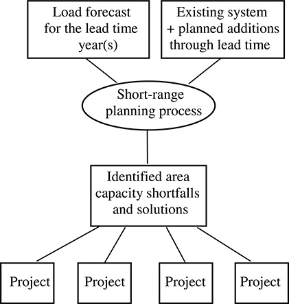
Figure 13.3 The short-range planning process consists of an initial planning phase in which the capability of existing facilities is compared to short-term (lead time) needs. Where capacity falls short of need, projects are initiated to determine how best to correct the situation. The load forecast is primarily an input to the short-range planning process, i.e., it is used to compare to existing capacity to determine if and where projects need to be initiated.
problems and solve them before they occur. The reason to look beyond the lead time, and to plan for the long run, is to assure the decisions being made have the most lasting value.
How can a planner know if a new distribution line, DG unit, or other electrical addition is a good investment, with a low lifetime cost and a high utilization over that lifetime? That lifetime begins when the new line is completed and put in place, which happens at the end of the lead time. Thus, long-range evaluation begins at the lead time and assesses cost, value, and equipment contribution over a lengthy period thereafter. Its purpose is to determine if the short-term decisions will have long-term value. Given typical economic factors, and considering the uncertainties in predicting conditions over the very long term, a ten-year period is generally considered the minimum for such economic evaluations.4
A good long-range planning process is an end in itself
Long-range T&D planning is one of the few legitimate instances where a process’s major goal is itself. The long-range plan, along with its accompanying budget estimates and indicators of economic factors for the future system, is the major goal of the long-range planning process. More importantly, it is crucial that this plan’s development be ongoing, that it be maintained and continuously updated in order to provide long-range evaluation, guidelines, and direction to T&D planning and investment decisions.
To study a new transmission line, substation, distributed generator, or other planned expansion item and determine its impact over a future period from five to 25 years ahead, the planners need to have a good idea of the future conditions throughout the time the new project will be in service. This includes a forecast of the future load levels it will be called upon to serve, as well as a description of the system and conditions within which it will operate. They need a long-range plan, not just for the particular facility they are planning, but as a backdrop to their evaluation of this project.
This long-range plan must lay out the economics (value of losses, etc.) and operating criteria (usually assumed to be the same as today’s) that will be applied in future operations. It must specify the load that will be served (long-range load forecast), and it must specify the other electric additions that will be made during the period (e.g., other DG units planned for future years). This is so their interaction and influence on the performance and economy of any proposed short-range addition or change can be fully assessed over a good portion of its lifetime.
4 When using typical discount rates (e.g., 11%) analysis of a ten-year period of service captures 66% of the present worth of a level investment with a 40-year lifetime, while a 15-year period captures 80% of its present worth. Thus 10- to 15-year periods that begin at the lead time see a majority of the present worth aspects of an investment, but not all.
Table 13.5 Purposes of the Long-range Plan
Definition of “future” for evaluation of short-term planning decisions. Identification of mismatches between levels - coordination of plans. Forecast of long-range budget needs (for financial planning). Identification of long-term direction and strategy. A basis for evaluation of new ideas or changes in procedure. |

Figure 13.4 The coordinated multi-level long-range plan, where the major goal is the maintenance of a long-range plan that identifies needs and development of the system, so that short-range decisions can be judged against long-range goals. Here, the load forecast is a part of the plan, and there is no “project oriented” part of the activities.
The long-range plan does not need great detail
A long-range plan needs only enough detail to permit evaluation of the economics and “fit” of short-range decisions regarding long-range system requirements. A long-range plan needs only a certain amount of detail, sufficient to its purpose. Effort beyond this is wasted.
Other functions of the long-range plan
A good long-range plan provides several other useful functions, as listed below. The first is the long-term economic evaluation discussed above, the reason why a long-range plan must exist if good economy of investment is to be assured. But there are other valuable contributions that the long-range plan makes to the planning effort, and to the utility as a whole:
• Forecast of long-range budget. The long-range plan identifies capital costs, operations and maintenance costs, and losses’ costs to the point that they can be estimated for budget and financial planning purposes.
• Identification of long-term direction and strategy. A long-range plan provides a clear direction and long-term strategy for the electric system’s future. It may not be the best direction or strategy, but good or bad, it shows engineer, manager, operator, marketer, and executive alike, the current vision of how electric power will be supplied.
• A basis for evaluation of new ideas or changes in procedure. Proposals for changes in standards or system design are difficult to evaluate unless they can be compared on a fair basis against present standards and future needs. A long-range plan provides a “base case” to which new proposals can be compared, whether they suggest adopting a new primary voltage (23.9 kV versus the current 12.47 kV) or other changes in approach.
• Coordination of planning among levels of the power system. At some level, someone benefits if the plans for transmission, substation, distribution and distributed generation levels of the system fit together well. To assure this, their plans must be coordinated. This is best done by looking at the long-term implications of their interactions.
This long-range plan must lay out the economics (value of losses, etc.) and operating criteria (usually assumed to be the same as today’s) that will be applied by the utility in its future operations. It must specify the load (long-range load forecast) the system will be expected to meet, and it must specify how the T&D planners expect to handle that load growth - what new facilities will be installed in the long run to accommodate the future pattern of load growth. Most importantly, it should specify how the various long-range plans at the sub-transmission, substation, feeder, and customer levels will fit together. The economics of interaction of all four levels, leading to a least-cost system, is assured by evaluation of long-term PW value in a coordinated manner - Figure 13.4 shows the major flow in the long-range distributon planning process, while Table 13.5 summarizes its key purposes.
Handling Uncertainty: Multi-Scenario Planning
An important point to bear in mind is that long-range elements in their plan do not have to be built, committed to, or even decided upon, for years to come. This means that the utility can change its mind, or beyond that, be of two or more minds at the same time. There can be more than one long-range plan.
Uncertainty in predicting major events is a major concern in long-range planning. Will a possible new factory (employment center) develop as rumored, causing a large and as yet un-forecasted increment of growth? Will the bond election approve the bonds for a port facility (which would boost growth and increase load growth)? Situations such as these confront nearly every planner. Those of most concern to distribution planners are those factors that could change the location(s) of growth.

Figure 13.5 Multi-scenario planning uses several long-range plans to evaluate the short-range commitments, assuring that the single short-range decision, fits the various long-range situations that might develop. This shows the scenario variations for the case involving two possible future events.
In the presence of uncertainty about the future, utility planners face a dilemma. They want to make no commitment of resources and facilities for load growth that may develop, but neither can they ignore the fact that there are lead times required to put facilities in place, and that the events could happen. Given the reality of lead times, planners must sometimes commit without certainty that the events they are planning for will, in fact, come to pass.
Ideally, plans can be developed to confront any, or at least the most likely, eventualities, as illustrated in Figure 13.5. Multiple long-range plans, all stemming from the same short-range decisions (decisions that must be made because of lead times) cover the various possible events. This type of planning, called multiple-scenario planning involves explicit enumeration of plans to cover the various likely outcomes of future events. It is the only completely valid way to handle uncertainty in T&D forecasting and requirements planning.

Figure 13.6 Four scenarios of load density maps for a large U.S. city. See text for details.
Uncertainty in T&D growth forecasts cannot be addressed by planning for the expectation of load growth
One of the worst mistakes that can be made in T&D planning, integrated or otherwise, is to try to circumvent the need for multi-scenario planning by using a single probability-weighted spatial forecast. Such an approach invariably leads to plans that combine poor performance (as evaluated with respect to both electrical and customer service) with high cost.
As an example, the forecast in Figure 13.6 shows a detailed spatial forecast of electric load growth over a twenty year period for a large city, done in 1993 (intermediate years were forecast, too, but are not shown). At the top are maps of load in 1993 and as projected 20 years later in the base case. This map is very close to what actually developed in the intervening 20 years, although with the 2008 recession, the overall load level and pattern of spatial distribution shown will not be reached until about 2016.
The difference in the two top load density maps represents the challenge that lay ahead of this utility’s planners in 1993 - design a system to deliver an additional 1,132 MW in the geographic pattern shown, and add that as needed to the system that was in place in 1993 over the 20 year period.
At the bottom in Figure 13.6 are two alternate forecasts each of which included a possible new “theme park and national historical center” - something like Disney World - that was being considered by an international entertainment mega-company at the time, at one of two sites. The park itself was 35 MW. The real impact on the metro area load would be because it would generate a need for new hotels, restaurants, and other entertainment venues, much as existed in Orlando at the time. Altogether it would cause tremendous secondary and tertiary growth, adding over 12,000 jobs to the region, and leading to an average annual growth rate of about 1.5% more than in the base forecast during the decade following its opening.
Thus, the theme park means an additional 260 MW of growth on top of the already healthy expansion of this city. The maps in Figure 13.6 show where and how much growth is expected under each of three scenarios:
1) no park (base forecast, considered 50% likely);
2) site A for the theme park (25% likely);
3) site B for the theme park (25% likely).
As can be seen, the locations of the additional scenario growth will be very much a function of where the theme park is located. Hence, the three scenarios make a difference in both the amount of equipment and new circuits needed, and where they would be located. T&D equipment will have to be re-located and re-sized to fit the scenario that develops. The problem that the planners faced at that time is that they had no certainty as to which of the three scenarios would work out.

Figure 13.7 The probability-weighted sum of the three forecasts in Figure 13.6. This is perhaps the worst forecast the T&D planners could use to develop their plans.
One thing the planners do not want to do is form a single forecast map based on a probability-weighted sum of the various possible forecasts, an “expectation of load growth” map. Such a map is easy to produce: it is just the sum of the three forecast maps, each weighted by its probability (Figure 13.7).
While mathematically valid (from a certain perspective, at least) this forecast map will contribute nothing useful to the planning effort - it represents a future with one-quarter of a theme park at location A, one-quarter at location B and the other half somewhere else. That is one scenario that will never happen. Using it as the basis for T&D planning will lead to plans that spread resources too thinly over too much territory. If the base scenario develops, it will have too much capacity in many places not needed. If either theme-park scenario develops, it will have about half the extra capacity needed to serve it in the right places, and half somewhere else. A plan based on a spatial expected load forecast would be, relative to any expected output, a poor plan. Planning with the forecast shown in Figure 13.7 guarantees only one thing: the T&D plan will be inappropriate no matter what happens. In particular, if either of the alternate scenarios occurs, the plan is very non-optimal.
13.4 THE T&D PLANNING PROCESS
Figure 13.8 shows the T&D planning process in overview, as it applies in modern utility cases. Figure 13.9 provides a bit more detail as to the flow of information and process, and will be referred to throughout the rest of this chapter. The exact organization and emphasis of these individual-planning steps will vary from one utility to another. What is important is that all are accomplished in a coordinated manner. Other chapters in this book will focus on the data, procedures, and analytical techniques needed in each step. Here, the emphasis is on what each of these steps is and how it fits into the overall planning process.
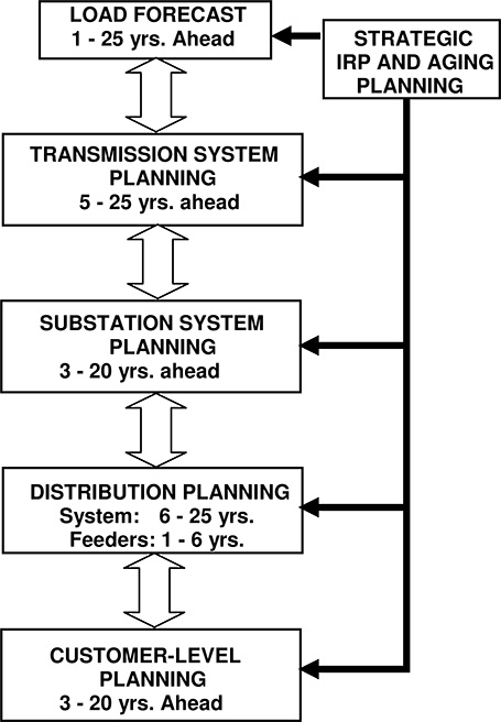
Figure 13.8 The basic T&D planning process involves six discrete stages.

Figure 13.9 The T&D planning process is driven by a strategic, corporate-level plan that includes the acknowledgment of aging issues the company has included in its plans, its business goals and criteria it wants to adhere to, and its corporate load forecast. The delivery planning process includes load forecast, and planning functions for transmission, substations, distribution, and customer levels, as well as maintenance of a coordinated long-range plan encompassing all the levels. Its inputs are the corporation’s forecast, strategic goals and planning and design criteria. Its outputs are the short-range projects.
Five of the six stages consist of both short- and long-range planning portions of length shown in Table 13.6. The strategic planning is only long-range in context. It might consider the short term, but is really a single comprehensive view of the long-term goals, direction, and consequences for the utility.
For the load forecast, “short-range” planning consists of producing a single “base” forecast - a non multi-scenario “most accurate” forecast for use in all short-range T&D planning. This needs cover no more than a decade ahead, that being the longest short-range planning period for any of the levels shown in Table 13.6. For the other four stages, short-range planning is aimed at achieving recognition of problems and definition of solutions within their lead time requirements.
Long-range planning is focused on evaluating the utilization and investment economics of all short-range projects, using a present-worth perspective or something similar. Short-range projects and decisions are judged against this sounding board of long-range performance. The load forecast can and often will be multi-scenario. Working for that, the long-range planning steps of all four subsequent stages are merged into a single, long-range T&D plan, with appropriate and coordinated representation of all system levels.
Table 13.6 Typical Short and Long-range Planning Periods for T&D System Planning

The short-range planning periods shown in Table 13.6 are recommended for normal utility circumstances. The long-range planning at each level begins at that short-range lead time and extends through a period at least twice and as far as four times farther into the future. In particular, if planners expect their results to address aging concerns and work toward solving them, planning must include a long-range element. Aging and its impacts are long-term issues and they can only be addressed through a long-term view. A short-term focus inevitably results in deferral of steps needed to reverse, stall, or at least mitigate age-driven trends.
Spatial Load Forecast
The planning process is driven by a recognition that future customer demands for power, reliability, and services may differ from those at the present. The load forecast projects future customer demand and reliability requirements, which define the minimum capability targets that the future system must meet in order to satisfy the customer demands. Forecasting for T&D planning requires a spatial forecast, as was illustrated in Figure 13.6.
Spatial forecasts: critical to aging infrastructure planning, particularly when on a tight budget
Chapter 8’s discussion of the problems traditional contingency-based planning encounters in dealing with modern utility systems demonstrated how one aspect of modern system interaction is a need for broader areas of contingency support. One result of this is that the interaction of capacity/load ratios in one area of a system, with that in other areas, is of greater importance in the overall performance of the power system. When a power system is loaded to modern (high) equipment utilization rates, and composed of aged (failure-prone) equipment, the reliability of service in one area of the system is sensitive to the quality of the planning done in nearby areas. All need each other for support, and a mistake in one area affects not just that area (as it did traditionally) but all its neighbors. The cost of making an error in matching capacity to peak load is much greater in contemporary power systems than it was in traditional power systems.
Spatial forecasts have always been an important element of good power delivery planning. But they take on an even more critical importance because of these aging infrastructure issues. The forecast of location of customer demand is as important in T&D planning as the forecasting of the amount of load growth: both are required in order to determine where facilities need to be located and what capacity they must have.
• Timing. Usually, spatial forecasts project annual figures (peak, etc.) over a period into the future or from three to five times the lead time of the equipment being planned - a spatial forecast for substation planning (five year lead time) would be carried out through 15 to 25 years into the future.
• Spatial resolution. Spatial forecasts are accomplished using the small area technique (Figure 13.10), dividing the utility service area into hundreds or perhaps tens of thousands of small areas and forecasting the load in each. As a general rule of thumb, the small areas must be no larger that about 1/10th the size of a typical equipment service area at that level, in order for the forecast to have sufficient “where” information for planning. Thus, spatial resolution needs are less at higher voltage levels - transmission can be planned with “small” areas that are perhaps 25 square miles in size, whereas substation planning must be done on a mile basis and distribution on a 40 acre (1/16 square mile) basis.
• Quantities forecast. A T&D forecast projects the peak demand (usually with respect to very specific weather called “design conditions”) at every locality, since these local peaks are what the T&D system must satisfy. In addition, simulation methods forecast customer type (residential, commercial, and industrial) and annual energy requirements (kWh).

Figure 13.10 A load forecast for T&D planning is accomplished by dividing the service territory into a number of small areas - either equipment service areas or the cells of a square grid - and forecasting customer demand in each.
Table 13.7 The Spatial Load Forecast Step

Table 13.7 summarizes key points and methods for spatial forecasting. The book Spatial Electric Load Forecasting – Second Edition (H. L. Willis, Marcel Dekker, 2002) presents details and practical advice on spatial forecasting, and reviews a number of popular spatial forecasting techniques. Some spatial forecast methods include an end-use based small area analysis, in which usage of electric energy by end-use (heating, water heating, lighting, etc.) is used to provide estimates for marketing and demand-side planning. Advanced methods may use end-use analysis to estimate the customer value of reliability of service. Cumulatively, these forecast characteristics of load location, amount, customer type and number, reliability, and service requirements set goals that the future system must meet. If the existing system cannot meet them, then additions or changes must be made to upgrade its capability.
Spatial forecast coordination with corporate strategic planning
There are a number of different analytical approaches and computer algorithms that are applied to spatial forecasts for T&D planning. What is best for any given situation depends on planning needs, data, and other details specific to a utility. But by far the most important aspect of the spatial load forecast, and good T&D planning, is that it be consistent with the corporate, or “Rate Department” forecast, which projects sales and revenues for the utility as a whole. The T&D forecast must be based upon the same assumptions and forecast as the corporate plans.
Strategic Planning
No long term goals can be dependably achieved without planning on when, where and how they will be achieved. Utility strategic planning incorporates three aspects that directly interact with and even dictate elements of the T&D plan:
- Budget. The utility’s business and corporate planning sets spending limits and constraints. These are passed on to the T&D planning process through the budget approval process and have been a part of traditional T&D planning for generations.
- Integrated Resource Plans. The utility’s plan with respect to the use of distributed renewable energy, energy efficiency, demand response, and market-driven incentive plans, along with Smart systems and energy storage heavily influences what is needed from the T&D system.
- Aging. Aging is a long term effect and one that will affect no only utility spending and performance, but also the characteristics of that spending and performance (how much is capital, how much is O&M; how SAIFI and SAIF vary from circuit to circuit and their volatility year to year).
T&D planning needs to not only acknowledge and comply with all three elements of the utilities strategy, but ideally be driven by the strategic plan. Conversely, the utility must include all three of these elements, with respect to its system, in its corporate strategy. Essentially it must develop a strategy in these three areas of delivery system concern, if it is to build a base for comprehensive and effective planning – and hence effective use of its investment.
In the context discussed here, corporate strategy is not a spatial planning process. Costs, profits, and risks are not spatial, because money is fungible: a dollar made in the downtown area is just as valuable as a dollar made in rural areas.5 As a result the corporate plan and strategy will be unspecific as to locations and interactions with aging areas of the system. Its preparation will need to address the fact that there are aging areas of the system, etc., but locational information is not needed and not used.
This lack of need for spatial detail eases the strategic planning process. As will be shown in examples later in Chapter 16’s example and in the Appendices, “big picture” planning has to deal with the fact that the utility has so many old units, etc. Detailed implementation of that strategy through the T&D plan, however, has to both deal with specific areas and equipments, and tie the way it deals with them back to those elements of the plan and those required for expansion and other purposes. Lack of coordination so tight it could be called integration of expansion planning and aging-equipment refurbishment and replacement programs, will lead to noticeable inefficiencies in the use of capital.
Transmission Planning
In modern (deregulated) utilities, “transmission” has two very distinct meanings applied to two very different parts of the power system:
Wholesale grid: The regional grid, which interconnects generating plants and key bulk switching stations around the region, and connects the regional power system to other regions, is composed of high-capacity transmission lines, typically of voltages between 230 to 765 kV. This is the portion of the system that creates the wholesale market in electric power, and assures open access to merchant generators and buyers alike. System security, rather than reliability, is really the key factor in assuring “dependability” here.
Sub-transmission: The term sub-transmission has been used for decades to designate those transmission voltage lines whose purpose is to deliver power to distribution substations. This is a mission quite distinction from that of the wholesale grid. Sub-transmission lines are generally of between 35 and138 kV, although some 230 kV lines exist primarily for this purpose.
The regional wholesale transmission grid is a key element in a healthy and economical regionally electric industry – it creates or enables the open access competitive market for electric power. The wholesale grid is usually planned and operated by an independent regional authority somewhat distinct, and often at arms-length from, the distribution utilities. Only part of the criteria and goals at this level relates to delivering power. Without doubt, one purpose of the wholesale grid is to deliver the required power to customers, but in addition, the transmission system is planned to provide:
5 In utilities with service areas that overlap multiple regulatory jurisdictions, such as those that serve customers in several states, strategic and corporate plans do have to take the variations in state regulation and policy into account. In this respect strategic planning can become spatial.
1. System Security and Stability – the ability of the system to maintain interconnected integrity subsequent to any reasonably likely failure or event, and to react to transient events in a smooth manner.
2. Generation access (deregulation) or generation dispatch (traditional) – provide sufficient electric tie strength between generation plants and the system to assure all plants can truly access the system – that transmission constraints do not limit choice of what generation can be run.
These two goals mean that a good deal of the transmission system is planned from the perspective of generation: permitting generation access the system, ensuring system security no matter what happens, and providing stability against major disturbances. These aspects of transmission planning are not directly concerned with meeting power delivery needs, but with assuring that the generation-grid level of the system provides a stable bulk transmission capability and open access opportunity for all.
Planning of the “generation-grid” combination, which includes most of the high voltage transmission, is an activity quite apart from what might be termed “sub-transmission” planning - the planning of power transfer capability to the distribution substations, which is the only type of planning relevant to power delivery planning.
In general, sub-transmission planning reacts only slightly with grid planning - the grid is planned and presented as a “given” to the sub-transmission planning process. This is particularly true because of the “Chinese wall” that often has to exist between the wholesale (open access) and retail (local Distribution Company) under deregulation.
Thus, the interaction of the planning processes at the transmission-grid/sub-transmission-junction, has the most limited “coordination” of any of the junctions between adjacent levels of the power system. Sub-transmission is part of the power distribution planning process. It is best done as part of the distribution planning process. The sub-transmission – substation – feeder system ought to be planned as one system.
Figure 13.9 shows the recommended relation of sub-transmission planning to the other stages of utility system planning. Key aspects of these relationships include:
• Transmission encompasses two planning functions: as mentioned above, the “generation-grid” planning which focuses on establishing a strong grid with security and dispatch freedom and meeting all power pool requirements, and the “sub- transmission” planning, which includes all planning activities related to moving power to substations so that it can be distributed to customers. Only “sub-transmission planning” is overtly a power delivery planning function.
• Forecast of future load for transmission planning comes through the distribution planning process. Fully half of the statistical variation in future loads due to “load growth” is a function of distribution planning (Willis and Powell, 1985). To the transmission-sub-transmission planning process, the “loads” to be served by the system being planned are the high-side loads of the distribution substations. How much load is collected to a particular substation depends on the distribution planning - whether load growth ends up at one substation, or another, or is split between them is determined by the distribution planning. This “high side substation load forecast” is best produced by starting with the spatial forecast, assessing the preferred patterns of distribution substation service areas in the distribution planning/substation planning stages, and then passing the target substation loads to the transmission planning process. If particular loads prove difficult to serve, transmission planning can provide feedback to distribution planning, asking if alternate possibilities can be considered.
• Coordination with substation planning. The transmission system must reach every substation. Therefore, sub-transmission planning needs to be coordinated with the siting, capacity planning, and scheduling of substations (which of course has to be coordinated with distribution system planning, as shown in Figure 13.10). This coordination involves planning and scheduling of the sub-transmission and substation levels in which the cost impacts among the levels are “traded” back and forth. In many utilities, all these functions are combined into one “sub-transmission level” planning process. Given that this is coordinated well with distribution planning, it is a good approach.
Table 13.8 summarizes the important elements of this part of the sub-transmission planning process.
Table 13.8 Sub-Transmission Planning
Purpose: |
short and long-range planning of facilities to deliver power to the distribution substations. |
Timing: |
short-range - 3 to 7 years; long-range - 5 to 20 years. |
Products: |
short-range - sub-transmission project schedule coordinated with substation and transmission grid plans. Long-range - a base sub-transmission plan. Coordination with: “transmission system” planning (EHV, grid, generation), substation-level planning (must deliver power to substations). |
Tools used: |
transmission network load flow and short circuit, route optimization software, combined sub-transmission-substation optimization programs. |
Substation Planning
In many ways, the substation level is the most important level of the system for two reasons. To a great extent this level fashions the character of the whole system. Substations are where the transmission and the primary feeder levels meet, the points to which the sub-transmission must deliver power, and from which the feeders must take it to neighborhoods throughout the system. The substation levels defines how and where cost, contingency, or capacity at one level can be traded or played against the other, and how expansion of both can be coordinated.
The substations’ sites set very definite constraints on the design and routing of the transmission and distribution systems - transmission lines must “end” at the substations and feeders must begin there. Substation location heavily impacts the cost and performance, and particularly the available design freedom, at both T and D levels. Substation capacity limits also heavily influence both transmission (how much incoming capacity is needed) and distribution (what amount of power can be distributed out of a substation).
As a result, regardless of whether substation planning is done as a separate planning function (about 20% of utilities), or as part of transmission planning (60%), or as part of distribution planning (20%), it should be interactively coordinated with both sub-transmission and feeder system planning. This means that communication should be explicit and frequent enough that glaring differences in marginal costs of expansion at the T, S, or D levels will come to the attention of the planning establishment in the utility and be dealt with by appropriate changes to the plan.

Figure 13.11 Residential and commercial growth in the shaded area is expected to add 31 MVA over the next decade. Either Edgewood or Kerr substation could be expanded at about the same cost to serve this growth. However, expanding the feeder system out of Kerr would be expensive - present feeder getaways are saturated, the system is underground and many duct banks are congested, and several geographic barriers make feeder runs quite lengthy. By contrast Edgewood’s all-overhead feeder system would be straightforward to expand, costing $1,900,000 less. Despite this, the overall optimal alternative is to expand Kerr, because transmission limitations at Edgewood would cost more to overcome than their savings at the distribution level.
For example, in Figure 13.11 distribution planners have made plans to expand Edgewood substation from 55 to 90 MVA capacity in order to serve a peak load that is expected to grow from 49 to 80 MVA due to load growth in the area indicated. Both Kerr and Edgewood substations are close enough to the load growth to pick up this new load, and either could be expanded with roughly the same plan and cost - addition of another 27 MVA transformer and associated equipment, at a cost of $750,000 PW.
However, from the perspective of the distribution system, expanding the feeder system out of Kerr substation instead of Edgewood would cost an extra $1,900,000 PW. Thus, Distribution Planning selected Edgewood for addition of new feeders and equipment to serve the load growth. But suppose that expanding transmission delivery capability at Edgewood by the required 31 MVA will require extensive reinforcement of towers and conductor, at a cost of $2,600,000 PW, whereas the changes needed at Kerr to accommodate a similar increase in peak load are minor and would run only $325,000 PW. Then it is best for the utility to decide to serve the new load out of Kerr, since even though Edgewood is the least expensive distribution option, when overall T-S-D cost is considered, it comes to $600,000 PW less to serve the load growth from Kerr.
The planning process at many utilities can not accommodate this very simple, common sense approach to cost minimization. The procedural “hand-offs” between transmission, substation, and distribution planning groups does not convey enough information, nor allow for sufficient back-and-forth cooperative communication, so that cost differences like this are noted and the planning process can recognize if and how to adjust to them. At many utilities, the distribution planners will pass no details other than the projected total load for a substation - “We need 80 MVA delivered to Edgewood.” At others the reverse happens, with transmission planners setting limits on substation capacity due to transmission constraints, without information of whether these could be eased if economically justifiable based on distribution costs.
Substation planning is important chiefly because of this requirement, that as the meeting place of transmission and distribution it defines their cost interaction. Planning procedures at this level ought to reflect this relationship and foster the required communication. There are at least three possible avenues to do so.
1. Planning meetings between transmission and distribution planning can be scheduled frequently and set up so that a free exchange of planning details, not just planning results, occurs. The authors are well aware of the institutional barriers that exist within many large utilities to this type of communication. In the case of one large investor-owned utility, the managers of the transmission and distribution groups, both of whom had been in their positions for over four years, had never met and had exchanged only a handful of formal “form reports” during their respective tenures. Under deregulation, there could well be formal procedures defining the limits of and requiring such cooperation. Regardless, the results of such communication are significant savings, and worth considerable cultural adjustment. Situations like the Kerr-Edgewood example occur more often than is recognized.
2. Use of methods and software for the sub-transmission, substation, and distribution planning functions that accepts marginal or incremental cost data for the other level, or for the substation level that accepts such data for both. For example, some service-area based optimization algorithms applied to substation-distribution system planning can accept transmission system cost curves for incoming capacity, cost which is included in the optimization.
3. A system of common planning procedures and nomenclature that sets typical target values for every level of the system and reports the incremental cost of all projects at any level, to all planners at other levels in routine, periodic reports. This would pass on to all the distribution, substation, and sub-transmission planners information for their use on the costs at other levels of the system. This provides the information, but not the incentive, for cooperation.
Table 13.9 Substation Planning
Purpose: |
short and long-range planning of facilities to control, transform and route power from T to D. Consideration of substation located DG, energy storage, and Smart controls. |
Timing: |
short-range - 3 to 7 years; long-range - 5 to 20 years. Products: short-range: substation project schedule coordinated with sub-transmission and distribution plans; long-range -long-range plan. |
Coordination with: |
sub-transmission planning, distribution planning, sustainability plan, Smart systems/technology strategy. |
Tools used: |
AM/FM-GIS systems, substation selection optimization applications, sub-transmission-substation-feeder system optimization applications. |
Frankly, application of all three of the above measures is best so as to lead to the most coordinated planning, which will minimize the potential for planning errors. Table 13.9 summarizes substation planning.
Feeder Planning
There are two very different aspects of “feeder planning.” The first is feeder system planning (Table 13.10), which involves the planning of the overall distribution feeder system in conjunction with the substations. The second, feeder planning, which involves the detailed layout of feeders and their specification is to a detailed engineering level of itemization and precision (Table 13.11).
Feeder system planning
What might be called “strategic” feeder planning involves determining the overall character of the feeder system associated with each substation, and with the role it plays in assisting in inter-substation contingency support. This includes determining the number of feeders from the substation, their voltage level, the overall service area served by the substation as a whole and the general assigned routes and service areas and peak loads for each. Additionally, operating problems (voltage, reliability, contingency switching) and overall costs may be estimated (budgetary).
Table 13.10 Feeder System Planning
Purpose: |
Long-range planning of the feeder system, mainly so that feeder impact of substation-level decisions is assessed for substation planning. |
Timing: |
Five to 20 years. |
Products: |
Evaluation of feeder-level cost and performance impact of all substation-level decisions; long-range feeder level cost estimates for budgeting. Integration of Smart technology into local delivery. |
Coordination with: |
Substation planning, customer-level planning. |
Tools used: |
Multi-feeder (multi-substation) optimization programs, combined substation-feeder system optimization application for capacity, reliability, economics. |
Generally, feeder system planning is 6 to 20 years ahead - well beyond any lead time for feeders but with considerably less detail than needed for short-range feeder planning. It is only a long-range and strategic planning activity, but it is an essential one. Its purpose is to provide “distribution system” feedback to planning decisions or alternatives being considered at the substation and sub-transmission levels and assess interactions of those levels.
As was mentioned earlier, the interplay of sub-transmission, substation, and feeder costs can be significant. In particular, the value of the primary distribution system associated with any particular substation probably outweighs the value of the substation itself. The 30-year PW of feeder losses on a heavily loaded system may exceed the value of both. Substation planning, particularly siting and sizing, can often be the economic equivalent of the tail wagging the dog. Small changes in location or planned capability can affect the cost of the feeder system dramatically and in some cases, a shift of one mile in the location of a suburban substation can have a PW impact of over $1,000,000.
Feeder system planning is often called multi-feeder planning to distinguish it from feeder planning which includes functions that can be done on a feeder by feeder basis. To be of maximum impact, multi-feeder planning should cover multiple substations, assessing how the feeder system interacts with substation capacities and costs - optimizing substation service areas while considering both substation and feeder costs (Figure 13.12). Proven techniques for simultaneous substation-feeder system planning exist and are described elsewhere in greater detail (Willis,2002).
Feeder System Planning is a Key Element of Reliability Planning for Aging Infrastructures
Chapter 8 highlighted the need to use the feeder system to provide load transfers and contingency ties between substations. Feeder system planning, aimed at making certain that sets of feeders associated with each substation can accomplish the required target levels for transfers under normal and contingency situations, is essential to assure dependable backup capacity in an integrated T&D system plan. Overall policy decisions on what type of switching support to have both within each substation area, and for transfer of loads between substation areas, is a multi-feeder design aspect. While some single-feeder planning has to be done as a follow-up to the decisions made at this stage, assurance of reliability via good contingency withstand and support capability at the feeder level is done on a system basis.

Figure 13.12 Multi-feeder system planning evaluates the performance of the entire feeder system associated with a set of substations. Its goal is to capture completely the interaction of substation level and feeder level constraints and costs to determine the overall substation-feeder optimum. A big part of this boils down to assigning “optimal service areas” to all substations while acknowledging capital and operating costs and electrical and geographic constraints at both the substation and feeder levels simultaneously, while determining the boundaries (dotted lines) between the substations.
Short-range feeder planning
Short-range feeder planning (Table 13.11) involves determining in detail the routing of each feeder and identifying its equipment to near engineering precision. In many utilities, feeder planning and feeder engineering are merged into one function - “Distribution Planning” produces completed feeder plans replete with detailed equipment specifications and route maps, pole locations, and all construction details. It also provides the final authorization and scheduling for construction.
Generally, feeder planning can be done on “a feeder at a time” basis, often using only load-flow and short-circuit analysis tools augmented by engineering judgment to determine alternative designs in a “trial and error” approach to find the best feeder layout. However, many modern CAD systems for feeder planning have load-flow and short-circuit applications that can be run on a number of feeders at once, and augment these with optimization utilities to help refine load balance and switching plan development among feeders. Feeder planning is done differently at every distribution utility, but there are standard recommended procedures that are well documented (Engel, et al. 1992; Burke, 1994; Willis, 2004). Table 13.11 summarizes its essential elements.
Purpose: |
Short-range planning of the feeder system, to produce project definitions and authorization for feeder additions and enhancements. |
Timing: |
One to five years. |
Products: |
Feeder system project specifications, schedule, and budget, accommodation costs for customer DG, etc. |
Coordination with: |
Feeder system planning, substation planning, customer planning, DG and DR planning, sustainability plan, and construction. |
Tools used: |
8,760-hour load models. “Feeder design” or CAD systems, feeder optimization programs (either single or multi-feeder), AM/FM and GIS systems. Reliability “load flows” for the design of optimized switching locations and branch and trunk tie capability. Possibly “shotgun” load flow macros that run 8,760-hour analysis on the year with and without DG & DR interactions. |
Customer-Level Planning
Traditional supply-side-only planning, through the first three quarters of the 20th century, included very little if any “customer-level” planning functions. Regulated utility IRP (integrated resource planning) of the type widely practiced in the late 1980s and early 1990s included a great deal of customer side measures to control load and efficiency - various DSM (demand side management) options were optimized on some type of societal resource-value basis, (see Willis and Rackliffe, 1994).
In the 21st century, “DSM” has expanded to include not just load-related adjustments and energy efficiency measures, but customer-owned generation and energy storage. It also includes much more emphasis on free-market driven incentives. Programs and policies in the 20th century envisioned utility control of load reductions. Their equivalents in the 21st century envision customer control and choice responding to real time and other market-driven incentives. Regardless, it appears almost certain that IRP will become the mainstream, expected approach for the industry.
For this reason, “customer-level planning” along with full consideration of customer-side resources and customer operation of them, can be expected to be an aspect in all power delivery planning. Table 13.12 summarizes key points in planning at the customer level. The interaction may be much more than just oblique, because customer actions with regard to load reduction, load scheduling, energy efficiency improvements, renewable generation, and energy storage can have a very substantial impact on T&D, since they affect the demand, the energy use, and the reliability needs the system must meet.
Customer-level planning often has a very long planning period, much longer than distribution planning, and often as long as that of generation. There are four reasons why both its short- and long-range planning periods are longer than almost all other levels of the system:
1. Lead time. While DSM programs can often be approved and implemented nearly immediately, it can take years of slow progress to obtain meaningful levels of participation - rates of 50% may take a decade or more to obtain. This “ramp up time” has the same effect as a long lead time.
2. Customer commitments. In starting a DSM program, a utility is beginning a very visible customer-interaction. Such programs are not entered into lightly and are often studied over the very long term to make certain the utility can feel confident it will commit to them for the long-term. Starting such a program and then canceling it several years later is not only costly, but leads to customer confusion and lack of confidence in the utility.
3. Proxy for generation. Customer side resources are often traded against generation in integrated resource planning. Comparison of the two resources needs to be done over the time span used for planning of generation, which means a present-worth or similar economic comparison over a 20-to-30 year period.
4. Uncertainty of resource. Even when the utility has absolute control of major customer loads such as space heating and cooling, there is still a small modicum of uncertainty about the available load reduction at any time, due to the variation in loads that might be on at that time. Taking such DSM measures, and the uncertainty in them fully into account is a normal part of good power delivery and energy resource planning and designing systems to achieve performance goals such as SAIFI targets and voltage regulation criteria.
But there is much more uncertainty about the availability of the customer side resources in an industry where the utility’s customers can respond to real-time price signals, and can or cannot operate their generation and storage as they see fit. Customers may or may not maintain their renewable generation over time. They may prefer to operate it differently than the utility expects. At peak periods customers will probably respond to price signals as expected, but perhaps they will not if it is an unusual situation. Even customers who originally buy energy storage systems as a reliability augmentation resource may begin using them, over time, to reduce cost/earn money via daily arbitraging of energy prices, changing the pattern of customer response the utility grew used to seeing on a daily basis.
Planners simply do not know the details of these customer-side response issues with the specificity that they know, say, the expected capacity of a feeder or a utility owned DG unit. That uncertainty needs to be taken into account in their planning of the delivery system’s capability and performance. It means achievement of traditional SAIFI targets, voltage regulation, and loading guidelines faces much more volatility. Where to put “a stake in the ground” with respect to the needed amount of power delivery capability is much more difficult.
Here, important aspects of regulatory policy and industry expectations have not yet been fully identified. Since the utility’s customers are now resource owners and operators, they can be viewed as partly responsible for performance lapses in the system’s ability to satisfy their energy needs. Does a customer who owns an energy storage system capable of powering his home or business for three hours have any right to complain that his lights went out when the local feeder was out of service for two hours? Does a homeowner who fails to maintain her 15 kW of PV panels so they are available during peak demand periods have a right to complain that voltage at her service entrance dropped to 108 volts? One can argue either side of these questions, and people will, because there is validity in some of the arguments on either side. Different solutions set different precedents and have far different implications on costs and benefits, particularly as to how the cost of the entire utility system is allocated to energy users via the utility’s rates. Regardless, eventually, policy and expectations will harden around a set of guidelines and expectations that the industry pretty much follows, but at present they are not yet fully formed. And regardless of what those are and how they are implemented, planning for customer-side performance targets and criteria will need to be done probabilistically, and planning for the attainment of the utility’s own business performance goals and targets will be messier, face more volatility, and require more comprehensive risk-mitigation methods than in the past.
Customer-level planning generally begins by adding more detailed, end-use and customer value attributes to the load forecast - forecasts by end-use and appliance category and of reliability value functions. It then tries to optimize PW cost of providing end-uses to the customers by juggling various DSM and T&D options. Generally, optimization methods function by balancing marginal cost of the various customer-side options against marginal cost curves obtained for the supply side. DSM and DG evaluation may also be part of value-based planning in which the utility and customer value functions are jointly optimized.
Table 13.12 Customer-Level Planning
Purpose: |
Short- and long-range planning of customer-level resources including DSM, DG, DS, RTP and TOU rates. |
Timing: |
One to 25 years. |
Products: |
Schedule of customer-side resource projects/programs; long-range plan of DSM/DG/DS targets. |
Coordination with: |
All levels of planning, corporate forecast/rate plan, spatial load forecast. Note: this planning is often done by corporate or rate department planners. |
Tools used: |
End-use load models. Integrated resource (T&D or otherwise) optimization. Customer response models. Value-based planning analysis. Eco-demographic models. Spatial customer/load forecast models. |
13.5 THE SYSTEMS APPROACH
Throughout this chapter, discussion of T&D planning has stressed the need to coordinate the planning of the various levels of the power delivery (T&D) system. The various levels – transmission, substation, and distribution – are interconnected, with the distribution, in turn, connected to the customers (and hence a function of the local load density). The best equipment types, sizes, and designs at each level of the system are a function of the types of equipment, sizes, and designs selected for the other levels of the system. In general, the equipment is so interconnected that it is impossible to evaluate any one aspect of design without taking all others into account.
Consider the question of substation spacing - determining how far apart substations should be, on average, for best utilization and economy. Within any service territory, if substations are located farther apart, there will be fewer of them, saving the utility the cost of buying and preparing some substation sites, as well as reducing the cost of building a large number of substations. Thus, overall substation cost is a function of spacing, but how it varies depends on land and equipment costs, which must be balanced carefully. With fewer substations, however, each substation must serve a larger area of the system. Hence, each substation will have a larger load, and thus require a larger capacity, meaning it must have more or larger transformers.
The larger substations will also require a larger amount of power to be brought to each one, which generally calls for a higher sub-transmission voltage. Yet, there will be fewer sub-transmission lines required (because there are fewer substations to which power must be delivered). All three aspects of layout are related - greater substation spacing calls for larger substations with bigger transformers, and a higher transmission voltage, but fewer lines are needed - and all three create better economies of scale as spacing is increased. Thus, transmission costs generally drop as substation spacing is increased.
Nevertheless, there is a limit to this economy. The distribution feeder system is required to distribute each substation's power through its service area, moving power out to the boundary between each substation’s service area and that of its neighbors. Moving substations farther apart means that the distribution system must move power, on average, a greater distance. Distributing power over these longer distances requires longer and more heavily loaded feeders. This situation increases voltage drop and can produce higher losses, all of which can increase cost considerably. Employing a higher distribution voltage (such as 23.9 kV instead of 13.8 kV) improves performance and economy, but regardless, it costs more to distribute power from a few larger substations farther apart, than to distribute it from many smaller substations close together. Feeder costs go up rapidly as substation spacing is increased.
The major point of this section is that all four of the above aspects of system design are interconnected: (1) substation spacing in the system; (2) size and number of substations; (3) transmission voltage and design; and (4) distribution feeder voltage and design. One of these factors cannot be optimized without close evaluation of its interrelationship with the other three. Therefore, determining the most cost-effective design guideline involves evaluating the transmission-substation-feeder system design as a whole against the load pattern, and selecting the best combination of transmission voltage, substation transformer sizes, substation spacing, and feeder system voltage and layout.
This economic equipment sizing and layout determination is based on achieving a balance between two conflicting cost relationships:
1. Higher voltage equipment is nearly always more economical on a per-MW basis.
2. Higher voltage equipment is available only in large sizes (lots of MW).
In cases where the local area demands are modest, higher voltage equipment may be more expensive simply because the minimum size is far above what is required - the utility has to buy more than it needs. How these two cost relationships play against one another depends on several factors: the load, the distances over which power must be delivered, and other factors unique to each power system such as the voltages at which power is delivered from the regional power pool, and whether the system is underground or overhead.
Figure 13.13 illustrates the difference that careful coordination of system design between levels of the power system can have in lowering overall cost. Shown are the overall costs from various combinations of T&D system layout for a large metropolitan utility in the eastern United States, all designed to achieve the same reliability targets. Each line connects a set of cost computations for a system built with the same transmission and distribution voltages (e.g., 161 kV transmission and 13.8 kV distribution) but varying in substation sizes (and hence, implicitly, their spacing).
In all cases, the utility had determined it would build each substation with two equally sized transformers (for reliability), with none over 75 MVA (larger transformers are too difficult to move along normal roads and streets, even on special trailers). Either 161 kV or 69 kV could be used as sub-transmission, either 23.9 kV or 13.8 kV could be used as distribution voltage. Any size transformer, from 15 MVA to 75 MVA, could be used, meaning the substation could vary from 30 MVA to 150 MVA in size. (Peak load of such substations can normally be up to 75% of capacity, for a peak load of from 23 to 100 MW.) Substation spacing itself is implicit and not shown. Given the requirement to cover the system, determining transmission voltage, distribution, and substation size defines the system design guidelines entirely.
Overall, the lowest cost T&D system guidelines are to build a 120 MVA, two-transformer (two 60 MVA units) substation fed by 161 kV sub-transmission and distributing power at 23.9 kV. This has a levelized cost (as computed for this utility) of about $179/kW. In this particular case, a high distribution voltage is perhaps the most important key to good economy - if 13.8 kV is used instead of 23.9 kV as the primary voltage, minimum achievable cost rises to $193/kW.

Figure 13.13 Overall cost of T&D system depends on the balanced design of the sub-transmission, substation, and feeder level, as described in the text. Cost can vary by significant margins depending on how well performance and economy at various levels of the system are coordinated.
The very worst design choices plotted in Figure 13.13, from an economic standpoint, would be to build 25 MVA substations fed by 161 kV sub-transmission and feeding power to 23.9 kV feeders ($292/kW). This would require many small substations, each below the effective size of both the transmission and distribution voltages, and lead to high costs. Overall, 161 kV and 23.9 kV are the correct choices for economy, but only if used in conjunction with a few, large substations. If substations are to be 25 MVA, then 69 kV and 13.8 kV do a much more economical job ($228/kW), but still don't achieve anything like the optimum value. The point is that achieving economy in power delivery involves coordinating the interactions, performance, and economies of the multiple system levels.
The Systems Approach Is Important for Aging Infrastructure Planning
The discussion and figure above showed the economic advantages that the systems approach can provide. These are certainly important to all utilities, including those facing aging infrastructure issues. However, there is another, and vital reason to apply the systems approach as a rule in all planning for aging T&D infrastructures:
The systems approach helps work around constraints in siting, size, or topology by drawing on the resources of the other levels in the power system to solve problems present at another.
As mentioned in Chapter 8, very often the owner of the aging T&D system is “stuck” with too few and too small substation sites. Sub-transmission rights of way may be narrow and non-optimal in routing. Expansion and addition may be costly, time consuming, and politically unacceptable.
Regardless, in many cases the utility has little choice but to make the best of these assets, particularly in aging areas of its system where additional land and rights of way are very expensive. The best way to improve performance is to seek out strengths in adjacent levels of the system in order to help support the weakness in another. Techniques discussed in Chapters 10, 11, and 14 can be applied to do just this, as was summarized in Section 13.5. More detailed discussions of the “systems approach” necessary to optimize the synergism among the sub-transmission – substation – feeder system levels to truly maximize the reliability/cost ratio of the entire power system chain are contained in the Willis (2004).
13.6 SUMMARY OF PLANNING IN AN AGING T&D INFRASTRUCTURE
Planning involves the selection of the best alternative from among those at hand. In the power industry, that selection depends to a certain extent on the values of the group making the decision. All cost evaluations for power delivery planning are based in part upon economic evaluation that is consistent over the range of all alternatives. Usually, this means that present and future costs must be compared. Present worth analysis, levelized costing, or some similar method of putting present and future value on a comparable basis will be used. While methods and standards vary from one company to another, the important point is that planners apply their company’s method consistently and correctly.
Traditionally, planning at many electric utilities has been something like a rhinoceros – never looking far ahead but instead focusing on only what is right in front of it, protective of its own turf, capable of surprising speed and powerful enough to get its way much of the time, but frequently content to move slowly and merely stay where it is. Utilities with aging T&D infrastructures need to revise their planning focus, taking the following lessons to heart:
• Good planning is more important that ever. A system that has weaknesses or high equipment utilization ratios is especially intolerant of planning mistakes.
• Optimization of reliability/cost is a key element of planning for aging T&D infrastructures.
• Constraints in siting, size, and routing are usually the major challenge in planning.
• Think of the long range, but act for the short range. Money and resources should only be committed on the basis of good short-term benefits and efficacy, but every commitment should fit into a coherent long-range plan.
• Spatial forecasting is more important that in normal T&D planning, important as it is in that venue.
• Feeder system planning, and coordination of feeder system strength to provide contingency support to the substation level, is a key factor in simultaneously achieving reliability and economy.
• The systems approach is a vital element of success in handling constraints in siting, sizing, and routing.
REFERENCES AND BIBLIOGRAPHY
D. Atanackovic, D. T. McGillis, and F. D. Galiana, “The Application of Multi-Criteria Analysis to a Substation Design,” paper presented at the 1997 IEEE Power Engineering Society Summer Meeting, Berlin.
T. W. Berrie, Electricity Economics and Planning, Peter Peregrinus Ltd., London, 1992.
J. J. Burke, Power Distribution Engineering – Fundamentals and Applications, Marcel Dekker, New York, 1994.
M. V. Engel, et al., IEEE Tutorial on Distribution Planning, Institute of Electrical and Electronics Engineers, New York, 1992.
R. Orans et al., “Targeting DSM for Transmission and Distribution Benefits,” Electric Power Research Institute, Palo Alto, CA, 1992.
F. Schweppe et al., Spot Pricing of Electricity, Kluwer Press, Cambridge, MA, 1988.
L. J. Vogt and H. L. Willis, “DSM: Transmission and Distribution Impacts,” Volumes 1 and 2, Report CU-6924, Electric Power Research Institute, Palo Alto, CA, 1990.
H. L. Willis, Power Distribution Planning Reference Book – Second Edition, Marcel Dekker, New York, 2004.
H. L. Willis and R. W. Powell, "Load Forecasting for Transmission Planning," IEEE Transactions on Power Apparatus and Systems, August 1985, p. 2550.
H. L. Willis and G. B. Rackliffe, Introduction to Integrated Resource T&D Planning, ABB Guidebooks, Raleigh, NC, 1994.
World Bank, Guidelines for Marginal Cost Analysis of Power Systems, Energy Department paper number 18, 1984.