Chapter 21
It’s a 3D World After All
IN THIS CHAPTER
![]() Understanding the basics of modeling in 3D
Understanding the basics of modeling in 3D
![]() Accessing modeling tools
Accessing modeling tools
![]() Specifying coordinates in 3D
Specifying coordinates in 3D
![]() Managing user coordinate systems
Managing user coordinate systems
![]() Changing the current working plane
Changing the current working plane
![]() Navigating in three dimensions
Navigating in three dimensions
![]() Applying visual styles
Applying visual styles
The addition of the Z coordinate releases your design work in AutoCAD from the planar world of two dimensions into a much more lifelike three-dimensional space. AutoCAD’s 3D capabilities have grown by leaps and bounds since AutoCAD 2007 was released with its souped-up 3D engine. Not only have the AutoCAD model creation and editing tools advanced, but it is now also a dab hand at visualization and rendering. You can view 3D models from any angle or slice through them to see what they look like inside. And finally, because the world of technical drawing is still a two-dimensional one, you can use AutoCAD’s viewing options to generate 2D drawing views from 3D models.
If you’re an AutoCAD LT user, just sit out most of this chapter and the next two. One of the major areas where AutoCAD LT differs from regular AutoCAD is in its extremely limited 3D functionality. Even viewing 3D models is much more difficult than necessary in AutoCAD LT. Those users can acquire nearly all the 3D viewing capabilities of the full version of AutoCAD, but you need a separate free program to do so. Just go to www.autodesk.com/products/dwg/viewers and download DWG Trueview.
This chapter takes a look at some of the tools available in AutoCAD’s 3D Modeling workspace and introduces you to many of the general concepts of creating 3D objects. You also discover how to look at your model from different viewpoints, and how to change the way it appears onscreen.
 Three-dimensional modeling and visualization is a lot more demanding on computer hardware than 2D drafting; 3D models tend to be bigger than 2D drawings, so you may need more disk space. And you’ll certainly be happier with more than the bare minimum of RAM required for 2D in AutoCAD. In the online extras for this book, I list AutoCAD system requirements and point out the increased resources needed for 3D work. In particular, note the desirability of using an engineering graphics card as opposed to a gaming card for heavy-duty 3D work.
The 3.5 Kinds of 3D Digital Models
Here are the three basic types of 3D computer models:
- Wireframe: Consists of edges and vertices only. Although they do occupy 3D space, they’re totally unrealistic and difficult to read correctly. AutoCAD can help you create wireframe models, but nobody does so any more. You only need to view a complex 3D model in wireframe mode to understand why.
-
Surface: Consists of infinitely thin skins that stretch from edge to edge of a model. AutoCAD can create two types of surfaces, and hence the 3.5 reference in the section heading.
- Mesh surfaces are composed of thousands and thousands of three- or four-sided faces. Mesh surfaces tend to be imprecise. Think of the mirror disco ball in a nightclub. From a distance, it looks like a sphere, but as you get closer you can see that it is made up of many small, flat patches. A terrible punster would say that they make a mesh of the model, but I would never stoop so low. Mesh surfaces are most often used for 3D animation or terrain modeling.
- NURBS surfaces: NURBS (Non-Uniform Rational Bezier Spline, if you must know) surfaces are far more precise (as you’d expect with a name like that!) and are frequently used in consumer product design. Think of a balloon as the surface model of a bowling ball.
Due to space limitations, I don’t cover either type of surface modeling in this book.
-
Solid: Has edges, surfaces, and mass. It’s a true 3D model, so you can do interference checking between them to make sure that the parts of an assembly will fit together properly. You can also find the surface area, volume, center of gravity, and moments of inertia of 3D models. Unfortunately, AutoCAD always assumes that the material has a density of 1. If your real-life part will be made from something other than water, you need to multiply the mass values by a suitable conversion factor, depending on the actual material being used.
 AutoCAD has several commands related to applying materials to solids, but they affect only the appearance and not the density.
Although surface and solid models are created and modified differently, the 3D objects that make up the models are made up of the same subobjects. The subobjects that a 3D object is made up of are
- Vertex: The 3D equivalent of an AutoCAD point object. Vertices are defined by a single X,Y,Z coordinate that can exist anywhere in 3D space, and are located at the corners of a 3D object. Spheres have no vertices.
- Edge: The boundary of a face, as defined by two X,Y,Z coordinates, one at each vertex. Spheres have no edges.
- Face: The surface area bounded by three or more edges, except for spheres, which are covered by one face.
Figure 21-1 shows a simple 3D object (a six-sided cubic shape created with the AutoCAD BOX command) and its subobjects.
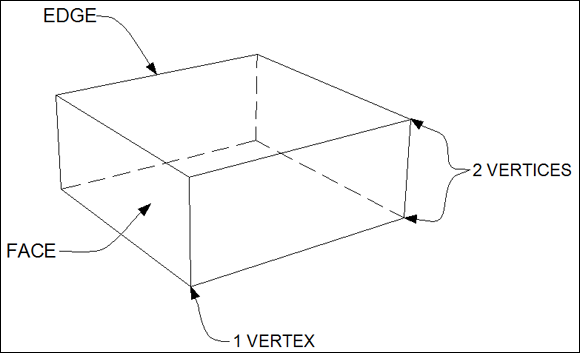
FIGURE 21-1: Subobjects of a 3D object.
Tools of the 3D Trade
AutoCAD includes a plethora of tools for creating, editing, viewing, and visualizing 3D models. You can find the most commonly used tools for 3D modeling on the 3D Modeling workspace’s Ribbon.
AutoCAD comes with two 3D workspaces: 3D Modeling and 3D Basics. I suppose the idea is that if you’re new to 3D, you get your feet wet with the 3D Basics workspace and then graduate to the 3D Modeling workspace after you gain some experience. Personally, I think that the 3D Basics workspace is a waste of time; my preference is to have the whole enchilada available from the get-go. In this book, I work exclusively with the 3D Modeling workspace.
AutoCAD’s 3D environment is a lot like its 2D version, with important differences. You should be aware of the following program settings and elements:
- Hardware acceleration: Graphics functions, such as changing visual styles and running 3DOrbit, can be processed on the main CPU — or, if hardware acceleration is enabled, on the graphics card. Turning on hardware acceleration, if your graphics card supports it (which I cover in the next section), nearly always improves 3D performance.
- Workspaces: AutoCAD comes with two 3D workspaces. I highly recommend that you use the 3D Modeling workspace. For more about the tools in the 3D Modeling workspace, see “Entering the third dimension,” later in this chapter.
- Drawing window: The drawing window’s background, cursor, and dynamic tooltip colors change when you switch between 2D and 3D views, and in 3D views when you switch between parallel and perspective projection. Click Options on the Application Menu, click the Display tab, and then click the Colors button to access color settings for the different interface elements. Note that I’ve tweaked the background color on my system so that it’s clear on the printed page. Unless you’ve made changes already, you’ll be looking at a very dark gray background rather than the light gray one in this chapter’s figures.
-
UCS icon: When you're working in 3D, the UCS icon shows the orientation of the current X,Y plane and the direction of the Z-axis. For information on using the UCS icon, see “Changing Planes,” later in this chapter.
Before AutoCAD 2012, the UCS icon merely showed you the orientation of the X-, Y-, and Z-axes. If you used the UCS command to set a new UCS, the icon reoriented accordingly. Starting in AutoCAD 2012, the selectable UCS icon is in the driver’s seat in that you can directly manipulate the icon to change the UCS.
Warp speed ahead
When you start AutoCAD for the first time after installing it, the program assesses your computer’s graphics card and — if it’s up to the task — enables hardware acceleration. With hardware acceleration, you can change the view of your model — even models with lighting and applied materials — in real time, with no deterioration in quality. Hardware acceleration also boosts the overall visual quality of drawing objects as well as regeneration performance.
Autodesk tests a wide range of cards and drivers with each new release. To find out whether your graphics card is supported for AutoCAD, check out the graphics hardware list online at http://usa.autodesk.com/adsk/servlet/syscert?siteID=123112&id=18844534.
If your graphics card is unsupported, you may lose some or all of the shading and rendering options such as shadows, reflections, transparency, and refraction. On the other hand, current generic graphics hardware is often acceptable unless you are doing heavy-duty photorealistic renderings of things such as complex machinery or highly detailed architectural models.
In any case, if AutoCAD automatically turns on hardware acceleration, you are probably good to go.
Entering the third dimension
If you’re new to the 3D game and you’ve been working in 2D until now, you need to do a couple of things before you can start a new 3D model in AutoCAD: You have to change the workspace, and then you have to open a new file by using a 3D template. The following steps explain how:
-
 Click the Workspace Switching button on the status bar and then choose 3D Modeling.
Toolbars, palettes, and Ribbon panels flash on and off, and soon AutoCAD settles down to display the Ribbon, as configured for the 3D Modeling workspace with a few additional panels.
-
Click the Application button and choose New; then click Drawing.
The Select Template dialog box appears.
-
Choose
acad3d.dwtif you’re working in Imperial units oracadiso3d.dwtif you’re working in metric. Click Open.A 3D modeling space appears (see Figure 21-2) where, rather than look straight down at the drawing area, you look at it at an angle from above.
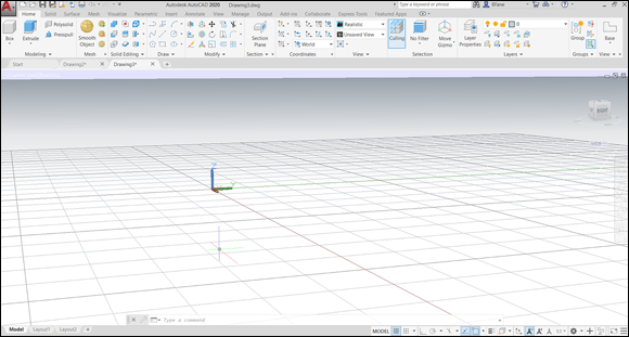
FIGURE 21-2: Ascending the Z-axis.
 To switch from 3D to the 2D world, simply click the Workspace Switch button on the status bar and choose Drafting and Annotation.
Untying the Ribbon and opening some palettes
You can access most of the AutoCAD 3D modeling tools from the Ribbon and 3D-related palettes. The following list introduces you to the Ribbon tabs and palettes available in the 3D Modeling workspace. Note that not all items in this list are visible in Figure 21-2 and that this list omits some items that aren't unique to 3D.
- Home: Contains a subset of the most frequently used 3D tools for creating and editing solids, surfaces, and meshes as well as user coordinate system (UCS) command options, view tools, 2D drawing and editing commands, and layer and group tools.
- Solid: Contains tools for creating and modifying 3D solids. I show you some of the finer points of solid modeling in Chapter 22.
- Surface: Contains tools used to create, edit, and analyze NURBS surfaces.
- Mesh: Contains tools used to create and modify meshes, convert them to solids, and generate live sections.
- Render: Contains tools to add lighting and materials to a 3D model, and generate rendered output. Chapter 23 presents the basics of rendering in AutoCAD.
- View: Contains tools to navigate, visualize, and change the current view and UCS of a 3D model. I cover navigation tools, coordinate systems, and visual styles in this chapter.
- Output: Contains tools to output a 3D model to a DWF or PDF file or even to generate a 3D print. I cover plotting 2D drawings in Chapter 16, and outputting 3D designs to paper isn’t significantly different. See the online Help system for specific information. I don’t cover exporting to 3D DWF or 3D printing in this book.
The following list describes what you can do with the palettes found on the View tab of the Ribbon:
- Materials Browser: Apply materials to the objects in the current model, and manage materials in saved material libraries.
-
Materials Editor: Apply, create, and modify materials in the current model. Chapter 23 introduces you to materials.
Applying materials in AutoCAD affects only the appearance and not the density or other properties. - Advanced Render Settings: Manage rendering presets.
- Visual Styles Manager: Create, modify, and manage visual styles in the current model.
The following palettes are found on the Render tab of the Ribbon:
- Lights in Model: Use this palette to manage lights in the current model.
- Sun Properties: Use this one to specify the lighting settings for the Sunlight system in the current model.
Modeling from Above
So far in this book, I’ve explained how to work with X and Y coordinates only. X and Y coordinates by themselves define a two-dimensional plane known (logically enough) as the X,Y plane.
In this chapter and in Chapters 22 and 23, you supply a third value — a Z coordinate — to locate geometry above or below the X,Y plane. You use the same methods to specify Cartesian (X,Y,Z) coordinates as the ones I set out in Chapters 1 and 8. You just add a comma and another number. The following techniques can be used to specify points in 3D:
- Coordinate and direct distance entry
- Point filter
- Object snap
- 3D object snap
- Object snap tracking
Using 3D coordinate input
I introduce you to 2D coordinate entry in Chapter 8. To recap, the input formats are
- Absolute Cartesian coordinates: Expressed as X,Y — the distances along the X- and Y-axes from the origin (0,0).
- Relative Cartesian coordinates: Expressed as @X,Y — the distances parallel to the X- and Y-axes from the last point.
- Relative polar coordinates: Expressed as @d<a — the distance and angle in the X,Y plane from the last point.
Do not enter spaces after the commas. AutoCAD treats the spacebar the same as Enter, and a space messes up the coordinates.
Although you can use these 2D coordinate input methods in 3D, you usually have to give AutoCAD just a little more information when you want to work in three dimensions. You can use absolute or relative Cartesian coordinates by simply adding a Z coordinate to the end. In addition, there are two 3D–only coordinate formats, both based on 2D polar coordinates. You can enter 3D coordinates with the following methods:
- Absolute Cartesian: Expressed as X,Y,Z. Working with absolute coordinates in 3D should look familiar because the input is like working in 2D except that you add a Z coordinate at the end.
- Relative Cartesian: Expressed as @X,Y,Z. Relative coordinates in 3D work just like they do in 2D except that you add the Z coordinate.
- Cylindrical: Expressed as @d<a,z. Cylindrical coordinates are similar to relative polar coordinates (d is the distance and a the angle from the last point in the X,Y plane) with the addition of a Cartesian Z coordinate to locate the point above or below the X,Y plane.
- Spherical: Expressed as @d<a1<a2. Spherical coordinates are also based on relative polar coordinates, but instead of a Z coordinate to specify a location above or below the X,Y plane, you specify an angle from the X,Y plane.
Using point filters
Coordinate entry (as described in the preceding section) is fine if you already know the coordinate values or distances in 3D space where you want to locate your points. Often, however, you may need to derive 3D points from existing geometry without knowing those exact values. Using point filters, you can locate new points based on existing points. You can use point filters to construct 2D and 3D coordinates.
When AutoCAD prompts you to specify a point, you can either enter point filter values at the command line or bring up the right-click menu and choose a filter option from the Point Filters submenu. After selecting a point filter option, specify a point to filter out part of the coordinate value and then enter the requested value. For example, use the -X,Y filter to enter your own Z coordinate value after specifying a point on the current working plane.
Object snaps and object snap tracking
![]()
![]() Object snaps allow you to accurately specify points on existing objects in a 3D model. You can use endpoints, midpoints, and center object snaps on 3D objects, but AutoCAD also provides a set of object snaps specific to 3D modeling.
Object snaps allow you to accurately specify points on existing objects in a 3D model. You can use endpoints, midpoints, and center object snaps on 3D objects, but AutoCAD also provides a set of object snaps specific to 3D modeling.
Three-dimensional object snaps allow you to specify points on 3D objects that regular object snaps don’t recognize, such as a vertex or the center of a face. You enable 3D object snaps by clicking the 3D Object Snap button on the status bar. Right-click the 3D Object Snap button and choose the running 3D object snap modes that you want to use.
![]() Object snap tracking allows you to calculate points that are not on an object by using object snap points on existing objects. When working in 3D, you can track points on not only the current X,Y plane but also along the Z-axis. While tracking points along the Z-axis, AutoCAD provides feedback in the form of a tooltip that lets you know you’re moving along the Z-axis in the positive or negative direction.
Object snap tracking allows you to calculate points that are not on an object by using object snap points on existing objects. When working in 3D, you can track points on not only the current X,Y plane but also along the Z-axis. While tracking points along the Z-axis, AutoCAD provides feedback in the form of a tooltip that lets you know you’re moving along the Z-axis in the positive or negative direction.
 The ELEVATION system variable allows you to specify a height above or below the current working plane. When you enter a 2D coordinate, AutoCAD uses the value assigned to the ELEVATION system variable (by default, it’s 0) to create a 3D coordinate. You can set the OSNAPZ system variable to 1, to substitute the Z coordinate value of a point specified by using an object snap with the value of ELEVATION.
Changing Planes
Come fly with us while I explain changing planes in AutoCAD. Just step through this metal detector over here while I x-ray your bags.
Okay, it’s not that kind of plane. This section covers using the user coordinate system (UCS) to control the current working (or X,Y) plane. The UCS icon, displayed either at the lower-left corner of the drawing window or at the origin (0,0,0), shows you the orientation of the current work plane and the positive direction of the Z-axis. I cover UCSs in Chapter 8.
Displaying the UCS icon
By default, the UCS icon is displayed in both 2D and 3D views. You can lose your bearings pretty easily when working in 3D, and I strongly recommend that you keep the UCS icon in your sights at all times. You can toggle it on or off by clicking the UCS Icon icon (yes, the UCS icon is labeled “UCS Icon”) in the Viewport Tools panel of the View tab on the Ribbon.
In previous releases, the UCS icon was merely a graphical indicator of the current coordinate system. If you set a new UCS in model space, the UCS icon adjusted to show you the orientation of the new X,Y plane and Z-axis. In other words, the UCS icon was driven by the current coordinate system. Beginning with AutoCAD 2012, the UCS icon moved across to the driver’s seat! You can select the UCS icon and see new multifunction grips that allow you to set a new UCS by dragging the grips on the origin and the legs of the icon. There’s also a right-click menu. You can enable or disable UCS icon selectability on the Settings tab of the UCS dialog box. Type UCSMAN and press Enter to open it. In the next section, I show you how to create a new UCS by selecting and manipulating the UCS icon.
Adjusting the UCS
Every drawing you create uses the World Coordinate System (WCS), but when working in 3D, you need to create additional work planes. For example, you might want to drill a hole on the angled face of a wedge. User coordinate systems (UCSs) are necessary when you need to draw objects on work planes other than the WCS. In the real world, think of latitude and longitude as the WCS; street naming, house numbering, and hotel room numbers are all local systems and are equivalent to UCSs. Traditional UCSs are static; create one, and it stays current until you change it. By default, such coordinate systems are unnamed, but you can assign a name and save it for future use.
![]() A couple of releases back, AutoCAD introduced Dynamic UCSs. Because dynamic is the opposite of static, what you get is a temporary coordinate system that changes as you move the mouse pointer over different planar faces of a 3D object. Click the Allow/Disallow Dynamic UCS button on the status bar, or press the F6 key to toggle Dynamic UCS on and off.
A couple of releases back, AutoCAD introduced Dynamic UCSs. Because dynamic is the opposite of static, what you get is a temporary coordinate system that changes as you move the mouse pointer over different planar faces of a 3D object. Click the Allow/Disallow Dynamic UCS button on the status bar, or press the F6 key to toggle Dynamic UCS on and off.
Name that UCS
The UCS command offers ten options to help you define a new UCS. Access the UCS command options from the Coordinates panels on either the View tab or Home tab of the Ribbon.
After you select one of these UCS options from the Ribbon, follow the command prompts at the command line or the Dynamic Input prompt.
- World: Align the UCS to match the WCS.
- Face: Align the UCS to the face of a 3D solid.
- View: Align the UCS so that the X plane is perpendicular to your current viewing direction.
- 3 Point: Specify a new origin for the UCS, and then the positive direction of the X- and Y-axes. Alternatively, use the multifunction grips on AutoCAD’s UCS icon to create a new UCS by moving and realigning the icon.
For more information on all the UCS command’s options, refer to AutoCAD’s online Help system.
The more UCSs in your drawing, the more you need help managing them. AutoCAD offers a handy-dandy UCS dialog box for doing just that. Open it by clicking the dialog box launcher (the little arrow at the right end of the panel label) on the Coordinates panel of the View tab or Home tab, or simply type UCSMAN and press Enter. The three tabs in the UCS dialog box are
- Named UCSs: Lists world coordinate system and other types of user coordinate systems. Set a UCS current with the Set Current button, or right-click a UCS to rename or delete a named UCS. You can’t rename or delete the World UCS.
- Orthographic UCSs: Lists the six default orthographic coordinate systems (front and back, left and right, top and bottom) relative to the WCS. These UCSs are automatically created by AutoCAD and can’t be deleted or renamed.
- Settings: Controls properties of both the UCS icon and the UCS.
After you define a UCS that you think you might want to use again, you can save it in the UCS dialog box. I explain how in the following steps, which you begin by creating a solid box:
-
Start a new 3D drawing by selecting
acad3d.dwt(oracadiso3d.dwtfor the metric crowd) for the template, and ensure that the 3D Modeling workspace is current.Refer to the steps in the “Entering the third dimension” section, earlier in this chapter, if you need a refresher.
-
 On the Modeling panel of the Home tab, click Box.
AutoCAD prompts you:
Specify first corner or [Center]: -
Type 0,0,0 and then press Enter.
AutoCAD anchors the first corner of the box at the origin of the WCS and prompts:
Specify other corner or [Cube/Length]: -
Drag the cursor away from the first corner and click a point to set the length and width of the box.
Exact distances don’t matter in this example. AutoCAD prompts you:
Specify height or [2Point]: -
Drag the cursor upward from the second corner and click to set the height of the box.
AutoCAD creates the 3D box and exits the command.
Then you define the UCS by following these steps:
-
Move the cursor over the UCS icon.
The UCS icon shows the orientation of the world coordinate system. As you move the cursor over the icon, it turns a greenish-gold color, indicating that it can be selected.
-
Click to select the UCS icon.
A square, multifunction grip appears at the origin, and round, multifunction grips appear at the ends of the icon’s legs.
-
Move the cursor over each multifunction grip and look at the grip menus.
Hovering over one of the round grips at the end of a leg lets you choose between realigning the selected axis and rotating the UCS around one of the unselected axes. Hovering the mouse pointer over the origin grip lets you move the UCS origin to a new location and either keep the current alignment of the X- and Y-axes or realign them. The third grip option, World, restores the WCS.
Now you use the UCS icon’s multifunction grips to set a new UCS.
-
Click the UCS icon to select it, and then move the cursor over the square, multifunction grip at the origin.
The cursor jumps to the origin, and the grip menu appears.
-
From the grip menu, choose Move and Align.
AutoCAD prompts you:
** MOVE AND ALIGN **Specify origin point or align to face, surface, or mesh: -
Move the cursor to a different corner of the box, and when the UCS icon origin is over the corner, click to set the new origin.
If you want, you can drag the round grips on the axes to realign the new UCS.
Finally, you have to save it. Follow these steps:
-
 On the Coordinates panel of the Home tab, choose UCS, Named UCS.
AutoCAD displays the UCS dialog box.
-
With the Named UCSs tab current, select Unnamed in the UCSs list.
The new, unnamed UCS is the current UCS in the drawing and is listed at the top of the list.
-
Right-click Unnamed and choose Rename from the shortcut menu.
An in-place editor is displayed that allows you to rename the UCS.
-
Type a name for the new UCS and press Enter.
The Unnamed UCS is renamed (see Figure 21-3).
-
Click OK.
The UCS dialog box closes, and the new UCS is saved in the drawing.
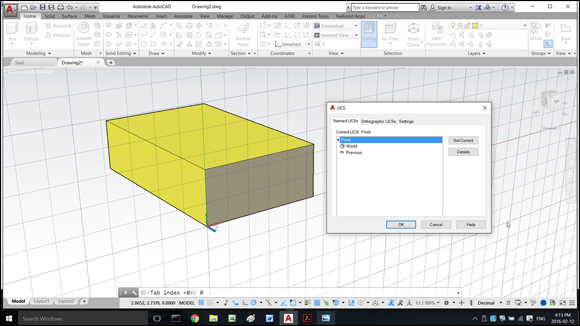
FIGURE 21-3: Naming a custom UCS.
To switch back and forth between the two UCSs, simply select the one you want to use from the Coordinates panel:
 Use WCS: On the Coordinates panel of the Home tab, choose UCS, World.
- Use your custom UCS: On the Coordinates panel of the Home tab, click in the Named UCS drop-down list and choose the name of the UCS you just saved.
AutoCAD likes giving you lots of choices. You can also restore a named UCS from the UCS drop-down list at the bottom of the ViewCube. I fill you in on the ViewCube in the “Taking a spin around the cube” section, later in this chapter. Or you can right-click the UCS icon, choose Named UCS, and then choose the UCS from the menu.
Using Dynamic UCS
![]() A named UCS allows you to work on different work planes, but it can take a bit of effort to set up, and that can distract you when you’re focused on 3D modeling. With Dynamic UCS, you can focus on modeling, not on creating a UCS. To enable or disable the Dynamic UCS feature, click the Dynamic UCS button on the status bar.
A named UCS allows you to work on different work planes, but it can take a bit of effort to set up, and that can distract you when you’re focused on 3D modeling. With Dynamic UCS, you can focus on modeling, not on creating a UCS. To enable or disable the Dynamic UCS feature, click the Dynamic UCS button on the status bar.
Figure 21-4 shows an example of drawing a circle on the side of a 3D solid. When Dynamic UCS is enabled, AutoCAD highlights the face of the 3D solid that the UCS will be aligned with. Click over the face to align the UCS with the face, and then finish the command. The circle is aligned with the face of the 3D solid, and the previous UCS is then restored.
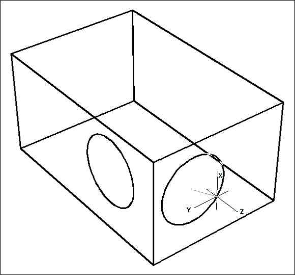
FIGURE 21-4: Dynamically create a UCS on a 3D solid.
Navigating the 3D Waters
If you’re new to 3D in AutoCAD, you may be wondering how to look at whatever it is you’re modeling from whatever angle you desire.
The easiest way to switch to viewing from a different direction is to use ViewCube (shown in Figure 21-5) to switch to a standard orthographic 3D view or an isometric view.
- The six standard orthographic (straight-on) views are Top, Bottom, Left, Right, Front, and Back.
- The four standard isometric views are SW (left-front), SE (right-front), NE (right-back), and NW (left-back). An isometric view is one in which you see the object from above — or below, but AutoCAD’s standard views don’t do below.

FIGURE 21-5: The 3D ViewCube.
Before I explain the ViewCube, however, here’s a bit of background information for you.
An isometric view is an unrealistic 3D view because all lines that are parallel in reality are also parallel in the view. In a perspective view, lines that are parallel in reality appear to meet at a vanishing point, as parallel lines appear to do in reality. (Think of railroad tracks heading across the prairie.) Isometric views are parallel projection views, and you can view 3D models by using those views in either the full version of AutoCAD or AutoCAD LT. Perspective views are more commonly used in architectural applications, and parallel views are more commonly used in mechanical design.
This warning is for AutoCAD LT users. Users of the full version of AutoCAD don’t need to worry. AutoCAD LT can open drawings created in the full version. Those AutoCAD drawings can be saved with perspective projection current, and if you open such a drawing in AutoCAD LT, you can see it in perspective. You can switch from perspective to parallel projection by changing the PERSPECTIVE system variable’s value from 1 to 0. Be careful if you do this, because you can’t change it back again! You could use UNDO to reverse the change, but if you save and close the drawing, you’re sunk.
The six orthographic and four isometric views work well for showing 3D models of common objects such as mechanical components and buildings. You can also change to plan view, which is a top-down view of either the world coordinate system or a UCS.
AutoCAD LT has limited 3D viewing capabilities. The same preset views are in both AutoCAD and AutoCAD LT, and you can also use the Viewpoint Presets dialog box (ddVPoint command) in which you set a viewing position by specifying angles in and from the X,Y plane. Finally, there’s the really ugly command-line-only VPOINT command, left over from last-millennium releases. Man, that one’s so ugly that it’s not even on the Ribbon!
Orbit à go-go
![]() Preset views are fine for many 3D modeling tasks, but if you really want to have fun, 3DOrbit (not in AutoCAD LT) is your ticket to it. Orbiting a 3D model in AutoCAD is similar in concept to orbiting Earth in a satellite, only a lot cheaper. The three orbiter modes are Constrained, Free, and Continuous.
Preset views are fine for many 3D modeling tasks, but if you really want to have fun, 3DOrbit (not in AutoCAD LT) is your ticket to it. Orbiting a 3D model in AutoCAD is similar in concept to orbiting Earth in a satellite, only a lot cheaper. The three orbiter modes are Constrained, Free, and Continuous.
 Free Orbit displays an arcball on the screen in the form of a circle representing a sphere around the object. You click various places inside, outside, and on the arcball and then drag to change the 3D view. The idea is that you’re spinning an imaginary sphere containing the model. As you drag the cursor, AutoCAD updates the screen dynamically.
Constrained mode is pretty much like Free mode with training wheels in that you can orbit only horizontally and vertically.
Continuous mode lets you leave a mode spinning continuously. To change the orbit direction and speed, simply click-drag-release the mouse. The model orbits in the direction defined by the mouse motion, and the orbit speed is determined by how fast the mouse was moving when you released its button.
While you’re using the 3DOrbit command, right-click and select Other Navigation Modes to switch between the three modes on the fly.
You might also want to experiment with different projection modes:
- Parallel projection is the default AutoCAD projection. Lines that are parallel in the 3D object remain parallel in the projected view on the screen.
- Perspective projection makes objects look more realistic (for example, train tracks appear to converge in the distance), but lines that are parallel in the model don’t appear parallel in perspective projection.
If you manage to 3DOrbit out of control and can no longer see the model, right-click to display the 3DOrbit shortcut menu and then choose Zoom Extents. The Zoom, Pan, and Preset Views options offer other ways to get the model back in your sights.
When you start orbiting with no objects selected, AutoCAD tries to update the display of everything in the model in real time; with a complex 3D model, the process can take some time. To speed things up or to simply regain your bearings, select some objects before you start orbiting. Then AutoCAD updates the display of the selected objects only. When you exit Orbit mode, the entire model redisplays based on the new viewpoint.
Taking a spin around the cube
With so much talk about hybrid devices these days, Autodesk decided to create its own, in the form of the ViewCube (not in AutoCAD LT). The interactive ViewCube tool (see Figure 21-6) provides visual feedback about the current viewpoint, and allows you to set a preset view current or orbit the model, restore a named UCS, and define and restore the Home view of a model.

FIGURE 21-6: ViewCube, the multifunctional viewing device.
To change the view of the model by using the ViewCube, you can do one of the following:
- Click a corner, an edge, or a face to align the current view with the same viewpoint represented on the ViewCube.
- Click and drag the main area of the ViewCube to orbit the view of the model.
- Click one of the roll arrows to rotate the current view 90 degrees.
- Click one of the adjacent face triangles to switch to the adjacent orthographic view that is indicated by the triangle.
- Click one of the letters (N, E, S, W), or click and drag the compass to rotate the view around the center of the drawing.
Home view is a special view you can define so that you have a known reference view in the model. That way, if you lose your bearings, you always have a way to get back home. You can restore Home view from the ViewCube or from the SteeringWheels right-click menus.
Grabbing the SteeringWheels
![]() SteeringWheels act as a kind of navigation hub that allows you to access several different 2D and 3D navigation tools from a single user interface. AutoCAD LT includes only the 2D Navigation wheel. AutoCAD (the full version) comes with the 2D Navigation wheel and three other wheels that are designed to be used with 3D modeling. The three additional wheels are
SteeringWheels act as a kind of navigation hub that allows you to access several different 2D and 3D navigation tools from a single user interface. AutoCAD LT includes only the 2D Navigation wheel. AutoCAD (the full version) comes with the 2D Navigation wheel and three other wheels that are designed to be used with 3D modeling. The three additional wheels are
- View Object: Contains tools to center a model in the current view, zoom in and out, or orbit around a model
- Tour Building: Contains tools to move the viewpoint forward and backward, look around the model from a fixed location, and change the elevation of the current viewpoint
- Full Navigation: Contains a combination of the tools found on the 2D Navigation, View Object, and Tour Building wheels with the addition of tools to walk around or fly through a model
All wheels include the Rewind tool, which allows you to restore a previous view. The Rewind tool is similar to the Previous option of the Zoom command.
When a wheel is active, move the cursor over the wedge that contains the tool you want to use. For many of the tools, you either click over the tool or click and drag to use the tool. Some tools support alternative versions of themselves when you press and hold the Shift key. To get an idea of what each tool does, hover the cursor over the tool to display a tooltip message. To read more about each of the wheels and the tools on them, see AutoCAD’s online Help system. To display the help that's specific to the wheels, right-click when a wheel is displayed and choose Help from the shortcut menu.
Visualizing 3D Objects
It really doesn’t seem like that long ago when the only way to view 3D models was in Wireframe mode, but the last several releases have dramatically improved AutoCAD’s visualization capabilities. It now has almost a dozen different display modes, called visual styles, that you can set with the click of a drop-down menu. Figure 21-7 shows the default visual styles, and you can add your own in the Visual Styles Manager palette.
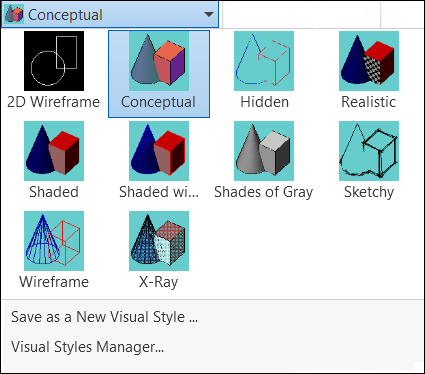
FIGURE 21-7: Some new styles to try on.
Visual styles are collections of settings that determine how a 3D model is displayed.
- 2D Wireframe: AutoCAD’s classic 2D viewing mode: full wireframe, dot-based grid, the 2D UCS icon, and no perspective.
- Conceptual: An illustrative kind of shaded view. Colors are unrealistic and edges are heavy, but you get a good sense of the model’s form. Refer to Figure 21-3 to see an example of the Conceptual visual style.
- Hidden: Looks slightly like Wireframe view (no surfaces are visible), but edges behind faces are hidden.
- Realistic: Fully shaded, but not rendered visual style; edges are not displayed, and a default ambient lighting highlights the faces with different intensities of the object color. Materials and textures are visible if they’ve been applied. Have a look at Figure 21-8 for an example.
- Shaded: Similar to Realistic, but with more subdued lighting. Textures do not appear in this visual style.
- Shaded with Edges: Same as the Shaded visual style, except that isolines are set to be displayed.
- Shades of Gray: Like Shaded, except that all object colors are changed to different intensities of gray.
- Sketchy: Does not apply shading to the faces of 3D objects, but gives the edges of 3D objects a hand-sketched look. Somehow, I’m not sure of the logic in spending several thousand dollars on hardware and software so that you can produce something that looks hand-sketched.
- Wireframe: Pretty much the same as 2D wireframe, except for background color, optional perspective, and the 3D (rather than 2D) UCS icon. Figure 21-4 shows a simple model in the Wireframe visual style.
- X-ray: Similar to Shaded with Edges, except that Materials and Textures are applied like the Realistic visual style, and faces are set to 50 percent opacity.
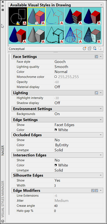
FIGURE 21-8: A manager for your visual styles.
AutoCAD’s preconfigured visual styles are only the beginning. You can modify any of the styles and create new ones in the Visual Styles Manager palette (refer to Figure 21-8).
![]() To display the Visual Styles Manager, click the dialog box launcher (the little arrow at the right end of the panel label) on the Visual Styles panel of the View tab, or enter VisualStyles or VSM at the command line and press Enter.
To display the Visual Styles Manager, click the dialog box launcher (the little arrow at the right end of the panel label) on the Visual Styles panel of the View tab, or enter VisualStyles or VSM at the command line and press Enter.
On a Render Bender
The different visual styles presented in this chapter are good for helping you navigate while you’re working on a 3D model. But when it comes time to impress a client, you need to use photo-realistic rendering, which I discuss in Chapter 23.