
CHAPTER 1
Setting Up Your Workbench |  |
BEFORE YOU START TO LEARN ABOUT electronics and electronic components, you will need to put together a few pieces of equipment that are required to build the experiments in this book. Figure 1-1 shows some of the basic tools you’ll need. Each piece of equipment is described in more detail in this chapter.
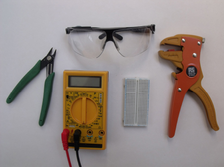
FIGURE 1-1 Some of the equipment you’ll need to build the experiments in this book. From top, moving clockwise: safety glasses, wire strippers, breadboard, multimeter, and wire cutters.
 INTERESTING FACT
Electronic components are the individual building blocks of every electronic circuit. You will be learning about some of the many different types of electronic components in Chapter 3. Each electronic component contains a number of attached wires and these allow you to connect several components together; these wires are sometimes called component leads.
Breadboard
Each of the experiments in this book shows you how to build an electronic circuit. If you are new to electronics, you might be wondering just what an electronic circuit is. You create an electronic circuit by joining several electronic components together using electrical wire. The results of creating a circuit can be complex or simple, such as causing a light to flash on and off.
You can build electronic circuits in several ways, but one of the easiest ways is to use a breadboard. Despite its name, a breadboard isn’t something you cut bread on! An electronic breadboard, or plugboard as it sometimes called, is a plastic panel that lets you connect and build electronic circuits without requiring the use of special equipment such as a soldering iron. Figure 1-2 shows some typical sizes and configurations of breadboard; these are the types that I used when building the experiments in this book.
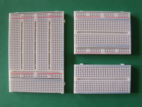
FIGURE 1-2 Various sizes of breadboard
Breadboard comes in many different sizes, shapes, and configurations, so you don’t need to use the same type of breadboard that I use. What you do need to understand, however, is how breadboard allows you to connect electronic components together. Notice that a breadboard contains lots of holes, which are sometimes identified by letters and numbers. Hidden inside the breadboard, underneath each of the holes, are connector strips that electronically link various holes together inside the board; you’ll use these holes to connect multiple component leads—the electrical wires—together.
Figure 1-3 shows an example of how these internal electronic connections are configured inside a typical breadboard.

FIGURE 1-3 The gray lines show how the internal connections of a typical breadboard connect various holes together.
Each hole in the breadboard is large enough for you to push an electronic component lead into it. The electronic connection inside the board then “grabs” the lead and makes an electrical connection to the other holes in the same row. The gray lines in Figure 1-3 show, for example, that holes a1, b1, c1, d1, e1, and f1 are all connected together. If you want to change a circuit layout, it’s simple: just carefully pull the component leads out of the board and start over.
 NOTE
NOTESome breadboard layouts may differ from those that I used to write this book, so always refer to the manufacturer’s instructions to identify which holes are connected together. If you use a different type of breadboard, you may need to modify the component layouts slightly to those shown in each chapter.
Each experiment in this book will show you a circuit diagram that will be explained in detail, and close-up photographs will show you how you can build the circuit on a piece of breadboard. Figure 1-4 shows you what a breadboard layout looks like (this is the breadboard layout for the water sensor experiment in Chapter 11). The breadboard layouts in this book don’t show the black lines that you can see in Figure 1-4, but they are shown in this photograph so you can see how the internal connections of the breadboard link the various component leads and wires together.

FIGURE 1-4 Each experiment shows a number of close-up photographs to help you build the breadboard layout.
Once you become more experienced in electronics, you will probably want to learn how to make your electronic circuits more compact and permanent. You’ll then need to learn how to build electronic circuits on stripboard or printed circuit boards by using solder and a soldering iron. But, for now, as you learn to create circuits, we’ll use a breadboard method that allows you to correct mistakes easily.
Interconnecting Wires
INTERESTING FACTA conductor is a material that allows electricity to flow through it; an example is copper wire. An insulator is a material that does not allow electricity to flow through it; an example is plastic, such as the plastic insulating sheathing that surrounds the wire.
Along with the internal connections inside the breadboard, you will often need to create additional electrical connections to the components that you insert. To do this, you will need to use some solid insulated copper wire of a suitable diameter and current rating, which has been suitably stripped (that is, the ends of the wire have been stripped of the plastic insulation so that the copper wires are bare). The stripped part of the insulated wire can then be simply pushed into the holes like the component leads—an example of this is shown in Figure 1-5.
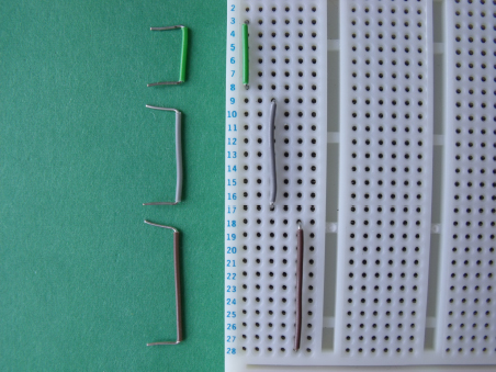
FIGURE 1-5 The interconnecting wires can be pushed into the breadboard holes.
NOTEYou should be able to purchase precut and prestripped interconnecting wires from the same electronic supplier that you purchase your breadboard from. However, you might find it more cost-effective to buy a roll of insulated solid copper wire from an electrical supplier and then cut and strip the wires to size yourself. You’ll read how to do this shortly.
Safety Glasses
You should always wear safety glasses to protect your eyes if you decide to cut or strip interconnecting wires or component leads. Safety glasses come in many different shapes and sizes, and it is important that you choose a pair that fit your head and face correctly and cover your eyes sufficiently. My safety glasses are shown in Figure 1-6.

FIGURE 1-6 Safety glasses
Always wear safety glasses when cutting or stripping wires or leads. Also, make sure that you hold one end of a component lead when cutting it to keep it from flying through the air into your or someone else’s eye. Also be aware that wire cutters and strippers are sharp and can cut into your skin.
Wire Cutters and Strippers
Wire cutters, like those shown in Figure 1-7, are useful for trimming interconnecting wires and can also be used to strip back the wire’s plastic insulation.
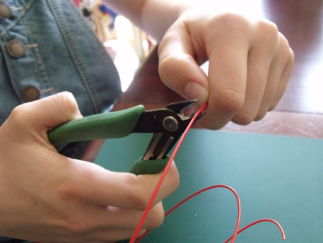
FIGURE 1-7 Wire cutters can be used to cut wires to size.
Figure 1-8 shows you how you can use wire cutters to trim back, or strip, the plastic insulation off the wires. Simply hold the wire in one hand while carefully cutting into the insulation (but not into the metal wire) with the wire cutters. Then, carefully slide the insulation away with the cutters. Make sure that you practice the technique on some scrap pieces of wire before you start a project; it takes practice to get it right.

FIGURE 1-8 You can also use wire cutters to strip the insulation from interconnecting wires.
You can also use wire strippers to strip the insulation, and these make the job a lot easier.
Wire strippers come in various shapes and sizes, and the type that I used to build the experiments in this book is shown in Figure 1-9. This photograph shows you how to strip the insulation from the wire: First, carefully insert the wire into the mouth of the strippers, and then squeeze the handle, as shown in Figures 1-9 and 1-10. This will produce a cleanly stripped cable. The strippers that I use include a wire cutter conveniently built into the handle, so I don’t need to use a separate wire cutter to cut the wires to size; I can simply squeeze the handle of the wire strippers to cut the cable, as shown in Figure 1-11.

FIGURE 1-9 Position the wire into the jaws of the wire strippers.
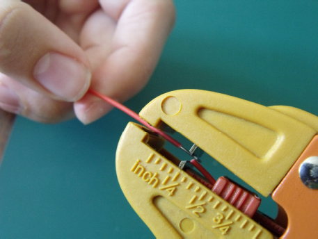
FIGURE 1-10 Squeeze the handle so that the jaws strip the insulation.

FIGURE 1-11 A handy cutting tool is sometimes built into the handle.
Always keep your fingers away from the stripping and cutting parts of the wire strippers. If you are not confident using wire cutters or strippers, ask a responsible adult to help you out.
Multimeter
A multimeter is a device used to take measurements in an electronic circuit, such as voltage, current, resistance, and capacitance. (You will learn about these measurements in Chapter 3.) A fairly basic multimeter that I have used for many years to build electronic circuits is shown in Figure 1-12.
This type of multimeter is sufficient for the projects in this book; it shows electrical measurements using a digital display. The price of multimeters varies from $10 to many hundreds of dollars, but you can get by with a basic multimeter to follow the experiments in this book; at a minimum, it should be able to measure voltage, current, resistance, and capacitance. You can also build the projects in this book without using a multimeter, but you’ll get the most out of the experiments if you use one.
Take measurements by connecting the meter to the circuit using the two leads and probes—more details of how to do this are described in each chapter. Some of the more expensive multimeters are called “auto-ranging” meters, which means that the meter automatically adjusts the reading on the display. Otherwise, basic multimeters require you to adjust the meter setting manually.

FIGURE 1-12 A multimeter should measure voltage, current, resistance, and capacitance.
Electronic Components
Without electronic components, we can’t build an electronic circuit. Chapters 2 and 3 discuss some of the different types of electronic components used in this book in more detail. Some of the electronic components that you will be using are shown in Figure 1-13.

FIGURE 1-13 A selection of electronic components that you will be using
NOTEThe component descriptions and part numbers required for each project will be outlined clearly in the parts list in each chapter. The book’s Appendix also suggests some useful resources to help you find components. Some experiments described in the book require you to use other household items as well, and these will be clearly outlined in each chapter.
Antistatic Precautions
Some sensitive electronic components, such as integrated circuits, can be damaged by static electricity. Static electricity can build up inside your body just by walking across a carpet, for example; have you ever gotten an electric shock when you touched another person or thing after walking across a carpet? This static electricity buildup can be transferred from your fingers into delicate electronic components, too, and it can sometimes damage them.
NOTEYou can learn more about electrical grounding and antistatic precautions on the Internet.
To remove static electricity from your body, you can wear an antistatic wristband with a strap and alligator clip connected to an antistatic mat; the mat is then connected to an earth point or ground, often supplied by plugging the mat into a three-hole electrical outlet. (In the United States, that third, round hole in the outlet is the ground. It’s connected to some wiring in the wall that disappears into the ground. In the United Kingdom, earth grounding for antistatic mats is sometimes achieved via a special plug that links everything to the “earth pin” of your household electricity supply.) You should be able to purchase these items from an electronics supplier.
 HINT!
HINT!Always avoid touching the metal pins of an integrated circuit when building your experiments.
Warnings Before You Get Started
Playing and experimenting with electronics can be fun, but you should be aware of some important things before you get started:
• Always read through each chapter first before embarking on building the experiment, and then build the experiments only if you feel confident in your ability to do so.
• Some experiments include flashing lights. If you are affected by flashing lights or suffer from epilepsy, please do not build these experiments.
• Electronic components are small and can be a choking hazard. Make sure that you keep them away from small children.
• The components in these experiments should not become hot in normal operation. If any of the components become hot, remove the battery from the circuit immediately and check that the circuit has been constructed correctly before reconnecting the battery.
• Never short out a battery. This can be dangerous and could cause the battery to leak or explode.
• Always connect electrolytic capacitors the correct way around in a circuit so that the positive lead is connected to the positive side of the circuit and the negative lead is connected to the negative side of the circuit. Connecting an electrolytic capacitor the wrong way can cause it to leak or explode.
• Never connect these experiments to the household electricity supply—mains electricity (the AC power in your house) can kill you.
• Each of the experiments has been tested extensively as part of writing this book; however, the author cannot guarantee the long-term performance, or accept legal responsibility for, the results of building these experiments. The reader builds the experiments outlined in this book at his or her own risk.
Ready for the Basics
You are almost ready to start building the experiments in this book. But before you start to build anything, you still need to understand some electronics basics. In the next chapter, you will do just that!
..................Content has been hidden....................
You can't read the all page of ebook, please click here login for view all page.