CHAPTER 18
Heads or Tails? Flip an Electronic Coin |  |
FOR SOME GAMES, YOU FLIP A COIN to see which player starts first. Each player shouts “Heads!” or “Tails!” to predict which side of the coin will face up before the coin is flipped—each player has a 50/50 chance of winning the coin toss. But a coin has no electronics inside! As an inventor, you want to find a way of creating an electronic circuit that does the same thing. This experiment shows you how to build it.
If you haven’t built the random number generator experiment in Chapter 17, you should do so before starting this experiment. The electronic coin uses a lot of the core electronic circuitry of the random number generator and shows you how, with some creative thinking, you can modify the circuit to produce a slightly different end result.
 |
Experiment 15
Flipping an Electronic Coin |
In this experiment you’ll use a seven-segment display to create a circuit that simulates a coin toss to show heads or tails. Before you read any further, though, think about how you might use some of the circuit modules that you have learned about in this book to create such a circuit. You might already have some specific ideas about how to make it; if that’s the case, that’s great, because you are already starting to think like an inventor.
You could create an electronic coin in many different ways. In this experiment, you’ll see the circuit that I created. I’ll explain my thought process behind the circuit design as I go.
This experiment flashes LEDs on and off. If you suffer from epilepsy or are affected by flashing lights, this experiment is not for you.
Making the Display Show Heads or Tails
If you have already built the random number generator, you’ve experimented with a seven-segment display and you discovered that you can create many different numbers, letters, and shapes on the display, depending on how you illuminate various LED segments. Figure 18-1 shows you how I imagined a seven-segment display would look for this experiment.

FIGURE 18-1 The three versions of the seven-segment display
Of course, a single seven-segment display is unable to show the words “heads” and “tails,” so I’ve shortened these to a letter h and a letter t to show the results of the coin flip. If you permanently illuminate segments E, F, and G of the display, it provides a good template upon which to create the two letters. Along with the template, then, you can simply illuminate segment C to produce the letter h or segment D to produce the letter t.
Now that the display is taken care of, you need a circuit so that segments C and D can be illuminated alternately to create the two letters.
Decade Counter
For the random number generator experiment, you used a 4026B IC to produce the output codes to show the numbers 0 to 9 on the display. For this circuit, you’ll use a different IC called a 74HC4017 decade counter, which has ten output pins (Q0 to Q9).
It is called a decade counter because it is able to count to ten. Every time this IC receives a clock signal (for example, from the output of a 555 astable timer IC), each output pin activates in turn, as shown in Table 18-1.
TABLE 18-1 How the Outputs of a 74HC4017 IC Work
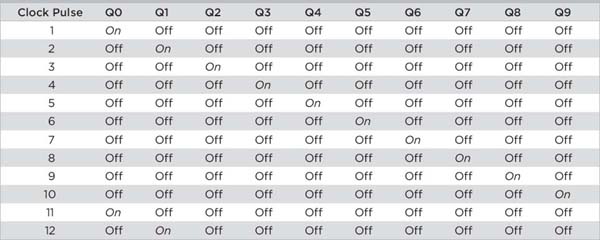
You’ll soon see how you can use just three of these output pins to create your electronic coin.
The Circuit Diagram
The complete circuit diagram is shown in Figure 18-2.
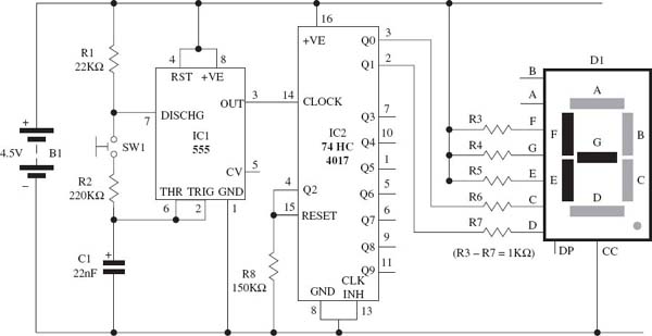
FIGURE 18-2 The circuit diagram for the electronic coin
If you compare this circuit diagram with the diagram for the random number generator, you’ll see quite a few similarities.
How the Circuit Works
The electronic coin is made up of four building blocks: power supply, input, control circuitry, and output. This circuit is powered by three 1.5 volt AA batteries that are wired in series to create a 4.5 volt power supply. The normally open switch (SW1) creates the input for this circuit. There are two main parts to the control circuit:
• A 555 timer (IC1) that is wired in astable mode; this creates the clock part of the circuit
• A 74HC4017 decade counter chip (IC2), which counts the clock signals from the 555 timer and converts them into the code shown in Table 18-1
The seven-segment LED display (D1) and its series resistors (R3–R7) create the output part of this circuit.
Notice that the seven-segment display (D1) has three of its LED segments permanently illuminated to create the template shown in Figure 18-1. These segments are E, F, and G, and they are connected to the positive supply rail using three resistors—R3, R4, and R5—so that they are permanently illuminated.
Assume for the moment that push-button switch SW1 is being pressed to close the circuit. When the battery is connected to the circuit, the 555 timer (IC1), which is wired as an astable circuit, starts to produce a fast train of pulses on its output pin 3. The timing speed of the astable circuit is determined by resistors R1 and R2 and capacitor C1. The output pin of the 555 timer is connected to the clock pin of IC2, which is a 74HC4017 decade counter IC. Only three output pins of IC2 are being used: pin 2 is used to activate segment D of the seven-segment display, pin 3 is used to activate segment C, and pin 4 is connected to the reset pin 15 of IC2 to reset the counter when it is activated. This means that IC2 operates as shown in Table 18-2 every time a clock pulse is received, and this continues in a never-ending loop.
TABLE 18-2 How IC2 Drives the Display

If you remove your finger from the switch (SW1), this takes resistor R2 out of the circuit and stops the 555 timer from producing pulses at pin 3; this shows the result of the coin toss to appear on the display.
Things You’ll Need
The components and equipment that you will need for this experiment are outlined in the following parts list. Prepare the items that you need before starting the experiment.
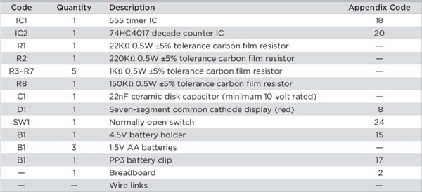
 NOTE
NOTEThe Appendix Code column of the table refers to specific parts that I used in this experiment. Information about sourcing these parts is outlined in the Appendix.
The Breadboard Layout
NOTERefer to Chapter 3 for building breadboard layouts and fault-finding guidelines.
The breadboard layout for this experiment is shown in Figure 18-3.

FIGURE 18-3 The breadboard layout for the electronic coin
If you have already built the random number generator, you’ll find it easy to modify that breadboard layout to create this one. You’re mainly replacing IC2 and changing some of the connections around the display. Notice the orientation of IC2 in this experiment: it differs from the orientation of IC2 in the last experiment.
Figure 18-4 shows a close-up of the display connections with the display removed. Figure 18-5 shows a close-up of the wiring around IC1 and SW1.

FIGURE 18-4 Display connections with the display removed

FIGURE 18-5 Close-up of the wiring around the 555 timer IC
Time to Experiment!
Now that you have built the breadboard layout, it’s time to play. Connect the battery to the circuit, and the display shows either a letter h (heads) or a letter t (tails), as shown in Figure 18-6.
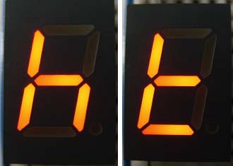
FIGURE 18-6 Displays showing “heads” and “tails”
Press the push-button switch (SW1) for a few seconds; you’re flipping the electronic coin! The display shows a letter b, because segments C and D are switching on and off very quickly, so it looks like both are illuminated at the same time. Now remove your finger from the button and you should see an h or a t on the display. Try flipping the coin a few more times to see if you can predict whether the coin will land on heads or tails.
Try changing the value of C1 to see what effect speeding up or slowing down the speed of the 555 timer has on the display. And if you decide to experiment with an electrolytic capacitor, make sure that its negative lead is connected to pin 1 of the 555 timer.
Summary
This experiment showed how I designed this electronic coin. It demonstrates how easy it is to connect various electronic circuits to produce a fairly complex design. Keep this breadboard layout when you are finished experimenting, because you will be using it again when you build the final experiment in Chapter 20.
..................Content has been hidden....................
You can't read the all page of ebook, please click here login for view all page.