
CHAPTER 17
Pick a Number! Create a Random Number Generator |  |
GAMES ARE PART OF OUR EVERYDAY LIVES, whether they are simple board games, more complex handheld electronic games, or games that use consoles. We like to play games because they can be exciting and they help us to pass the time. I’m sure that lots of times you have been so engrossed in playing a game that you lose track of time—before you know it, several hours have passed. This part of the book contains experiments that let you explore how you can use various electronic building blocks to creating your own electronic game circuits.
We’ll start with an experiment to create a random number generator, kind of like an electronic die. This experiment introduces you to some new electronic components and shows you how to build an electronic random number generator that produces a random number between 0 and 9.
 |
Experiment 14
Creating a Random Number Generator |
If you have played a board game, you will have noticed that they usually require at least one die (or two dice), like the one in Figure 17-1.

FIGURE 17-1 A simple die
A die has six sides and contains a number of dots that represent the numbers 1 to 6. To use a die, you usually throw it on a tabletop, and the number that lands on top tells you to move a certain number of spaces in the game.
This experiment is split into two parts: the first part introduces you to a new LED component (a seven-segment display), and the second part shows you how to build the random number generator.
This experiment flashes LEDs on and off. If you suffer from epilepsy or are affected by flashing lights, this experiment is not for you.
Experimenting with a Seven-Segment LED Display
For this experiment, you will be using an LED display that can show numbers between 0 and 9. This type of LED is called a seven-segment display and is shown in Figure 17-2. (This display contains seven individual LED segments configured in the shape of a number 8, plus an additional LED for the decimal point, which means that the display actually contains eight LEDs! You’ll ignore the decimal point in this experiment, however, and concentrate on the seven main segments.) This display might look familiar, because similar displays are used in lots of different household applications, such as the timer on a microwave and the lighted display on a DVD player.

FIGURE 17-2 The seven-segment LED display used in this experiment includes the pin connections on the top and the bottom of the component. (Note that if you use a different seven-segment display in your experiment, the pin-outs may be different.)
Each LED can be illuminated individually, and the combination of LEDs illuminated will determine which number is displayed. Each LED segment is identified by a letter A to G; these are not shown on the seven-segment display but are usually shown on circuit diagrams and manufacturers datasheets.
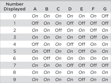
Table 17-1 shows which LED segments must be switched on to produce the numbers 0 to 9. It’s like reading a secret code—each number has its own special combination. If, for example, you want to show a number 3 on the display, the LED would need to illuminate segments A, B, C, D, and G. Notice that to create a number 8, all segments are illuminated.
TABLE 17-1 How Numbers Are Created on a Seven-Segment Display
The type of seven-segment display that you are going to use in this experiment is a common cathode (CC) type, which means that all of the cathode leads (negative connections) of each of the LEDs are linked together, like the one shown in the circuit diagram (Figure 17-3) for this part of the experiment.
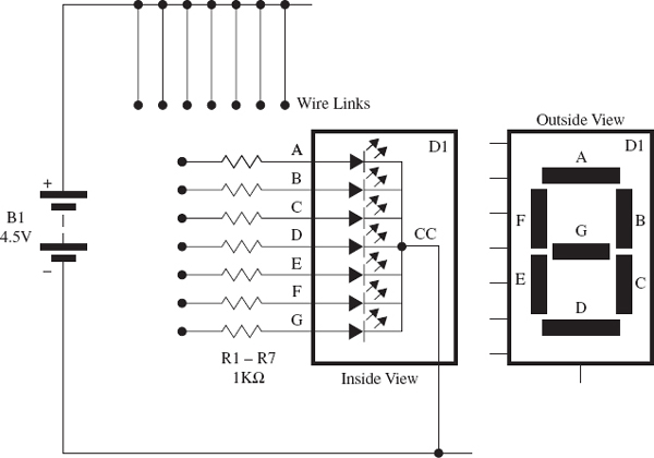
FIGURE 17-3 The circuit diagram for the seven-segment display experiment
 NOTE
NOTEThe Appendix Code column of the table refers to specific parts that I used in this experiment. Information about sourcing these parts is outlined in the Appendix.
Things You’ll Need
The parts that you’ll require for this part of the experiment are outlined in the following parts list. Prepare the items that you need before starting the experiment.
 NOTE
NOTEAnother version of seven-segment LED display is also available, called a common anode type. Can you guess how each of the LED segments is connected in this type of display?

FIGURE 17-4 Experimenting with a seven-segment display to create a number 3
You can experiment with the CC display using seven individual 1KΩ resistors and a piece of breadboard, as shown in Figure 17-4. In the figure, I have used five of the wire links to connect various resistors to the positive side of the battery to create the number 3 on the display. You can see that these five wire links are connected to resistors A, B, G, C, and D.
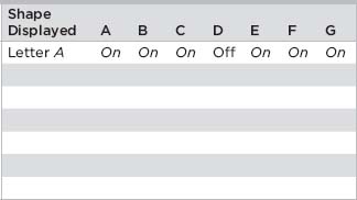
Once you have built the breadboard layout to create the number 3, you can experiment a bit more by adding or removing wire links to illuminate various LED combinations. Use Table 17-1 as a guide to creating the numbers 0 to 9 on the display. Then try different combinations to see if you can produce other shapes and even letters on the display. You can use Table 17-2 to record some of your findings; an example is shown at the top of the table.
TABLE 17-2 What Other Shapes Can You Create?
 INTERESTING FACT
There are a total of 128 different display combinations that can be produced using a seven-segment display. This is because each segment has one of two states; it is either illuminated or switched off. The total number of display combinations can be calculated by multiplying 2 by itself 7 times; 2 × 2 × 2 × 2 × 2 × 2 × 2 = 128. See if you can create them all!
Building a Random Number Generator
Now that you’ve experimented with a seven-segment display and understand how it works, you’re ready to build a random number generator circuit.
The Circuit Diagram
If you have been reading this book from the start and have been working through each of the experiments, you should be familiar with circuit diagrams. The circuit diagram for the random number generator experiment is shown in Figure 17-5. Do you recognize parts of this circuit? It might look complicated, but if you break it down into its individual building blocks, it is much easier to understand.

FIGURE 17-5 The circuit diagram for the random number generator
How the Circuit Works
The random number generator is made up of four building blocks: power supply, input, control circuitry, and output. This circuit is powered by three 1.5 volt AA batteries that are wired in series to create a 4.5 volt power supply. The normally open switch (SW1) creates the input for this circuit. There are two main parts to the control circuit:
• A 555 timer (IC1) that is wired in astable mode; this creates the clock part of the circuit.
• A 4026B seven-segment counter chip (IC2), which is a new component to you. It counts the clock signals from the 555 timer and converts them into a code that can drive the seven-segment display.
The seven-segment LED display (D1) and its series resistors (R3–R9) create the output part of this circuit.
Assume for the moment that push-button switch SW1 is being pressed to close the circuit. When the battery is connected to the circuit, the 555 timer IC (IC1), which is wired as an astable circuit, starts to produce a train of pulses on its output pin 3. The timing speed of the astable circuit is determined by resistors R1 and R2 and capacitor C1. The output pin of the 555 timer is connected to the “clock” pin of IC2, which is a seven-segment counter IC. Every time IC2 is “clocked,” it produces a coded output on its seven pins 6, 7, 9, 10, 11, 12, and 13, which produce the numbers 0 to 9 when connected to the correct LED segments in the display. These coded outputs are similar to the codes in Table 17-1. If you remove your finger from the switch (SW1), this takes resistor R2 out of the circuit and stops the 555 timer from producing pulses from pin 3. You’ll see how this works shortly.
Things You’ll Need
The components and equipment that you will need for this part of the experiment are outlined in the following parts list. Prepare the items that you need before starting the experiment.
 NOTE
NOTEThe Appendix Code column of the table refers to specific parts that I used in this experiment. Information about sourcing these parts is outlined in the Appendix.
The Breadboard Layout
NOTERefer to Chapter 3 for building breadboard layouts and fault-finding guidelines.
The breadboard layout for this experiment is shown in Figure 17-6. Follow this layout to build your breadboard—take your time, because many connections are required. Make sure that you use the 2.2μF electrolytic capacitor for C1 when you first build the breadboard layout, ensuring that the positive lead of the capacitor is connected to pin 2 of the 555 timer.
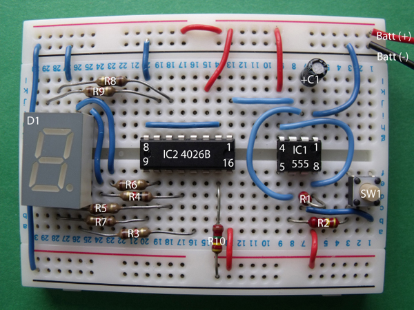
FIGURE 17-6 The breadboard layout for the random number generator
To help you better see the circuit, the display connections are shown in more detail with the seven-segment display removed in Figure 17-7.

FIGURE 17-7 The breadboard layout with the seven-segment display removed
Figure 17-8 shows the layout from a different angle to help you identify the connections around the 555 timer and switch SW1.
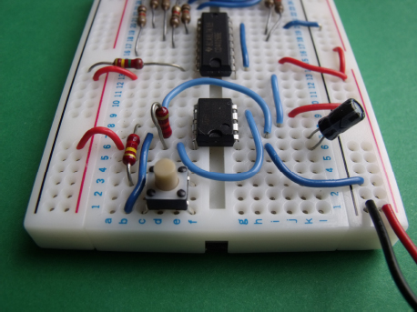
FIGURE 17-8 Wiring around the 555 timer and switch
Time to Experiment!
Once you have built the breadboard layout, connect the 4.5 volt battery to the circuit. The display shows a number—either a 0 or a 1. Now press the switch and keep your finger on it; the display starts to count slowly from 0 to 9 in a never-ending loop. If you remove your finger from the switch, the count stops and remains on a number until you press the button again. Impressive, isn’t it!
You might be thinking at this point that the circuit is not really suited to creating a random number (as a die can do when you toss it), and you are right; you need to make a few adjustments to get this right.
First, increase the speed of the 555 timer to make the count go a lot faster. Do you know how you might do this? If you read Chapter 5, you’ll remember that you can change the speed of a 555 timer by altering the values of its timing resistors and capacitors. In this experiment, you’ll change the value of capacitor C1 to do this.
Remove the battery from the circuit and remove the 2.2μF capacitor (C1). Replace it with a 10nF ceramic disk type, as shown in Figure 17-9.
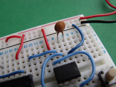
FIGURE 17-9 Change the capacitor to a 10nF ceramic disk version.
Next, connect the battery again to see a number on the display. Then press the switch for a few seconds, and you should see a flashing number 8 on the display. This happens because the 555 timer is producing clock pulses at a much faster rate because of the capacitor value; the display is changing from 0 to 9 very quickly, making it difficult to see which number is being displayed.
Remove your finger from the button, and you’ll see a number on the display. Since you can’t see which number will appear when you remove your finger (because the display is changing so quickly), the number that appears is equal to a random number. Now press and release the button a few times, and you will see that it is very difficult to predict which number you will end up with.
Congratulations! You have built an electronic random number generator!
Summary
In this chapter, you learned about seven-segment displays and how they can be used to create numbers 0 to 9 along with various letters and shapes. You also learned how two different electronic circuits can be joined together to produce an interesting effect.
If you’re in a mathematical mood, you could calculate the frequency of the 555 timer by using the astable formula from Chapter 5 to see how the astable speed changes when you alter the value of C1 in your experiment.
Keep the breadboard layout from this experiment, because you will be making some modifications to it in Experiment 15 in Chapter 18.
..................Content has been hidden....................
You can't read the all page of ebook, please click here login for view all page.