
CHAPTER 13
Step Inside! Make a Pressure-Sensitive Mat |  |
THIS CHAPTER SHOWS YOU HOW YOU CAN modify the basic alarm circuit that you built in the last experiment to make it work more like a proper burglar alarm. Before you start this experiment, you need to have read Chapter 12 and built the experimental alarm circuit, because you will be using it as the basis of this experiment.
 |
Experiment 10
Making a Pressure-Sensitive Mat |
In Experiment 9, you built a basic alarm circuit that illuminated an LED for a 25-second period when a pair of alarm contacts was connected. The circuit used a 555 timer in monostable mode. The circuit diagram for the basic alarm circuit is shown in Figure 13-1 and the breadboard layout is shown in Figure 13-2.

FIGURE 13-1 The circuit diagram for the basic alarm circuit

FIGURE 13-2 The breadboard layout for the basic alarm circuit
Additional Features
To make the circuit more like a real burglar alarm you need to add two features to the experiment:
• Make a pressure-sensitive mat that can be connected to the alarm contacts. This could be positioned inside your bedroom door, so that when someone steps on it, the alarm will be triggered. (You could buy a premade pressure-sensitive mat from a shop that sells security products, but where’s the fun in buying one when you can build it instead?)
• Replace the LED with a component that makes a noise when the alarm is activated. A loud noise will be more of a deterrent to a would-be burglar than just an LED.
These two additional features will be explored in this chapter.
Things You’ll Need
The household objects and components that you will need for this experiment are outlined in the following table. Prepare the items that you need before starting the experiment.


 NOTE
NOTEThe Appendix Code column of the table refers to specific parts that I used in this experiment. Information about sourcing these parts is outlined in the Appendix.
Build the Mat
The following steps and illustrations explain how to build the pressure-sensitive mat.
1. Cut two pieces of cardboard approximately 3-by-3 in. square (75-by-75mm).

2. Wrap each piece of card tightly with a sheet of aluminum foil.
3. Strip the insulation from two long pieces of wire, and use clear tape to attach the bare wire to the rough side of each piece of aluminum-covered cardboard.

4. Cut five lengths of adhesive sponge strips and apply them to the smooth side of one piece of aluminum-covered cardboard. Then attach a second layer of strips on top of the first layer to double the thickness.
5. Press the other piece of aluminum-covered cardboard onto the adhesive strips so that the two pieces of cardboard stick together. The two pieces of aluminum should now be separated from each other by two layers of adhesive strips.
6. Twist the two wires together to make the connection stronger, and wrap the complete assembly with some cling film so that the pad is totally insulated.
You have now created your pressure-sensitive pad!
You can test your pressure-sensitive pad by placing it underneath a rug or a mat and connecting the two wires to your multimeter on the continuity setting. If you step on the mat, the multimeter should bleep, showing that electrical contact has been made (Figure 13-3). This happens because your weight pushes the two pieces of aluminum foil together so that they touch each other.

FIGURE 13-3 Test that the pressure pad works using your multimeter.
If you step off the mat, the meter should stop bleeping, because the sponge pads push the two pieces of aluminum foil apart. Try walking on and off the mat to make sure that it works as expected.
The pressure mat that you have made is able to switch only very small currents like those used in this experiment. Do not try to use the pressure pad to operate buzzers or LEDs directly.
The Circuit Diagram
Now that you have built the mat, the next stage is to modify the original alarm circuit slightly so that you can replace the LED with a buzzer. The modified circuit diagram is shown in Figure 13-4.
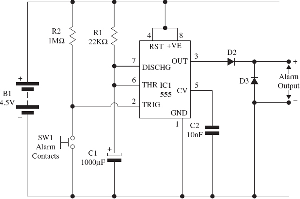
FIGURE 13-4 The circuit diagram for the modified alarm circuit. Notice how the value of C1 is 1000μF in this circuit which creates a 25-second time period.
How the Circuit Works
Notice that the modified circuit diagram no longer contains the LED and its series resistor; these components have been replaced with two diodes that are configured so that they can operate a 6 volt buzzer. If you compare this output configuration to the circuit diagram for the indicator lights in Chapter 8, you will notice that this diagram is similar to the circuit that operates the relay coil. The 555 timer is able to switch enough current to drive a small buzzer directly, and the two diodes are required to operate it correctly. The rest of the circuit operates in the same way as the previous experiment. Whenever the pressure-sensitive mat is activated, it triggers the alarm contacts and operates the 555 monostable circuit, and the output of this circuit operates the buzzer for 25 seconds.
NOTEThe 555 timer IC used in this experiment is able to activate a buzzer directly so long as the current rating of the buzzer is less than 200mA; some variants of the 555 timer can only switch up to 100mA; therefore, you need to make sure that your buzzer has a current rating lower than 100mA. Experienced electronics designers and inventors might want to design electronic circuits that switch higher currents; to do this they might decide to use a relay to switch the device instead (you can read more about relays in Chapter 8).
The Breadboard Layout
The modified breadboard layout is shown in Figure 13-5. Notice that the LED and resistor have been replaced with the two diodes, D2 and D3. The 6 volt buzzer can then be connected to the breadboard as shown.
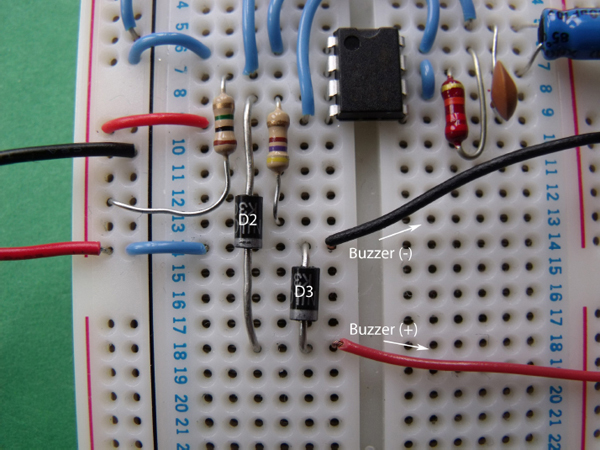
FIGURE 13-5 The modified breadboard layout
The two cables of the pressure-sensitive mat can be plugged in place of the alarm contact wires. The final experiment should look like Figure 13-6.

FIGURE 13-6 The final layout for the burglar alarm
Time to Experiment!
Now that the circuit is complete, you can try it out. Connect the batteries to the circuit, and you should find that nothing happens yet. Either step on the pressure pad or press on it using your fingers; this should activate the buzzer for a period of 25 seconds.
If this works as expected, you can set up the burglar alarm in a place that you want to protect. For example, you can hide the pressure pad under a mat in your bedroom. Switch on the alarm when you leave your room, and then, if someone enters your room and steps on the mat, he or she will get a big surprise. The buzzer will make a loud noise that will frighten away the intruder, and it will also warn you that someone has entered your room so that you can investigate. It won’t matter that they have stepped off the mat, because the monostable circuit that you built will continue to operate the buzzer for 25 seconds!
 HINT!
HINT!You can connect the pressure mat to some longer cables so that the breadboard is positioned further away from the mat.
Summary
In this experiment, you learned how to build a pressure-sensitive burglar alarm using some common household objects: you created a normally open momentary switch. Because of the simple materials and methods you used to make the switch, you may not realize that you have also created a capacitor.
If you read Chapter 3, you know that a capacitor is basically two metal plates that are separated by an insulating material. Think about the pressure pad: you used two aluminum plates separated by a sponge tape, which creates an air gap and this acts as an insulator. Figure 13-7 shows a pressure pad attached to the capacitor connections of my multimeter. The reading shows that the pressure pad has a capacitance of around 45pF, which is a very low capacitance.

FIGURE 13-7 Your pressure pad also has a capacitance rating!
..................Content has been hidden....................
You can't read the all page of ebook, please click here login for view all page.