
CHAPTER 10
Beep! Beep! Make an Electronic Horn |  |
SUPPOSE YOU’RE DRIVING DOWN THE ROAD IN your car and you need to warn another car or a pedestrian that you’re approaching. You wouldn’t lean out of the window and shout, “Get out of the way!” Instead, every car comes complete with an electronic horn, which is normally situated behind the front grill of the car. The horn is activated by a switch that is usually positioned in the center of the steering wheel. Pressing the steering wheel will activate the horn, which normally makes a noise that’s loud enough for other cars and people to hear.
This experiment explores how you can build a miniature horn like the one shown in Figure 10-1.
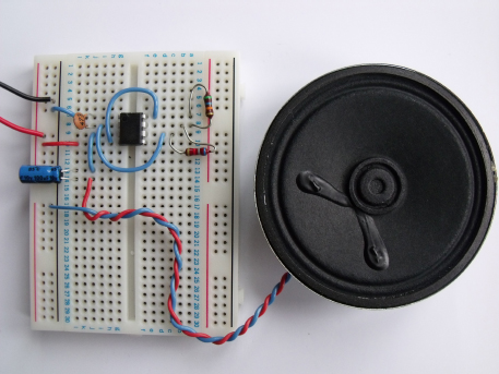
FIGURE 10-1 The electronic horn experiment
You could use this experiment to create a horn for your bike.
 |
Experiment 7
Making an Electronic Horn |
You can make electronic sounds and noises in many ways, and a few of these are discussed in this book. If you completed the experiment in Chapter 7, you made an electronic telephone and used a crystal earpiece that let you to capture and reproduce the sound of a friend’s voice. A crystal earpiece will not create a noise loud enough for a horn, so you’ll need to use a different component for this experiment. Figure 10-2 shows three different electronic components that you can use to create some serious noise. These are an electronic buzzer, a piezoelectric disc, and a small loudspeaker.
All the electronics required to create noise are normally inside the enclosure of an electronic buzzer. You can simply connect the buzzer to a suitable battery source and it will make a loud buzzing noise. The two other devices in Figure 10-2 require additional electronic circuitry to create noise: the piezoelectric disc, which you won’t be using in this book, and the small loudspeaker that you will be using in this experiment.
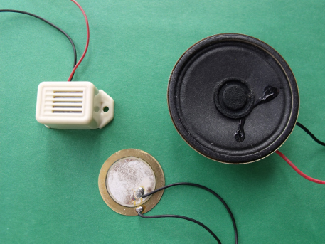
FIGURE 10-2 Various noise-making components; from left to right: electronic buzzer, piezoelectric disc, and a small loudspeaker
You can buy premade electronic horns that make a really loud sound, and this is the type of horn that car manufacturers tend to use. But that’s no fun—why buy a horn when we can make one from scratch using just six components?
What Is a Loudspeaker?
This experiment uses a loudspeaker like the one shown in Figure 10-2. If you have been following the experiments in order, this will be the first time that you will have used a speaker. Loudspeakers are used to broadcast sounds in radios, sound systems, and TVs. The circuit symbol for a loudspeaker is shown here:

A speaker normally has two connections, which are sometimes marked + and – to show which side you need to connect to the positive and negative points in a circuit, respectively. Inside the speaker is a coil of wire that acts as an electromagnet (similar to, but not the same as, a relay, which you learned about in Chapter 8). When a signal is presented to the speaker connections, the changing signal activates the coil and this in turn creates vibrations in the speaker, which in turn vibrates the air and thus creates a noise that you can hear.
The Circuit Diagram
The circuit diagram for the electronic horn experiment is shown in Figure 10-3. Look at it carefully and compare it with the circuit diagram for Experiment 2 in Chapter 5. It should look familiar to you.
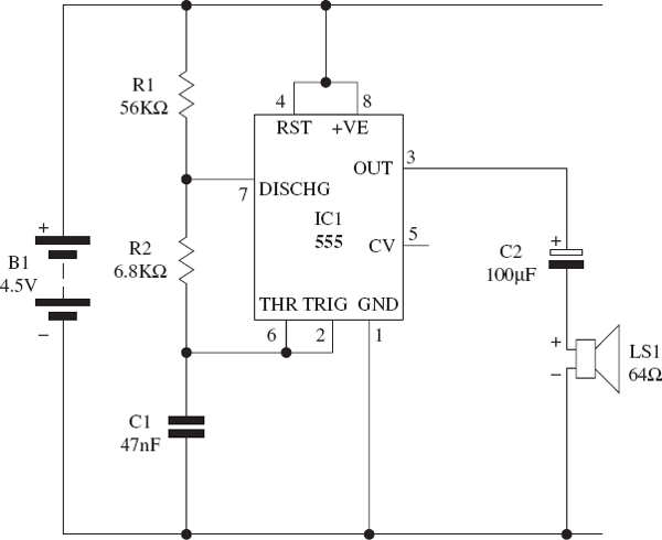
FIGURE 10-3 The circuit diagram for the electronic horn
How the Circuit Works
This circuit is made up of three building blocks: power supply, control circuitry (555 astable pulse generator), and output. The circuit is powered by three 1.5 volt AA batteries that are wired in series to create a 4.5 volt power supply. The control circuitry should be familiar to you if you have read Chapter 5, where you learned how to make a flashing LED. The control circuit contains a 555 timer (IC1) configured in astable mode, and its on-off time is set by the values of R1, R2, and C1. The capacitor (C2) and the speaker (LS1) create the output part of this circuit.
The heart of the circuit is a 555 timer in astable mode. You know that the timing of the 555 timer’s output depends on the component values of the two resistors (R1 and R2) and the capacitor (C1). The timing of this circuit produces a very fast train of pulses that lets us create a noise. In previous experiments that used this method, the timing pulses have been fairly slow, at around 1Hz; in this experiment, the timing sequence pulses at around 860Hz (860 times per second). The output pin 3 feeds these pulses into a capacitor (C2), which then feeds into the speaker. The purpose of the capacitor (C2) is to remove the direct current (DC) element of the signal and provide an output that the speaker can convert into noise. This fast pulsing output vibrates the speaker at such a rate to create a loud buzzing noise that emulates a car horn.
Things You’ll Need
The components and equipment that you will need for this experiment are outlined in the following table. Prepare the items that you need before starting the experiment.

 NOTE
NOTEThe Appendix Code column of the table refers to specific parts that I used in this experiment. Information about sourcing these parts is outlined in the Appendix.
The Breadboard Layout
Using the components in the table, build the circuit by following the breadboard layout for the electronic horn shown in Figure 10-4.
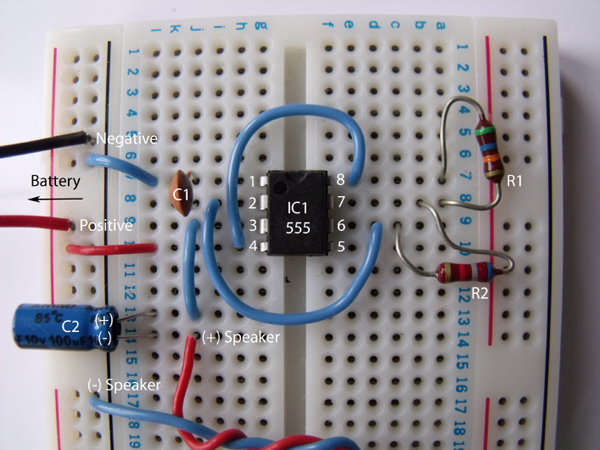
FIGURE 10-4 The breadboard layout for the electronic horn
NOTERefer to Chapter 3 for building breadboard layouts and fault-finding guidelines.
Notice that capacitor C2 is an electrolytic device, so it needs to be connected in the circuit the correct way around.
Your speaker may not have cables connected to it; if this is the case, you can simply use some insulated solid copper wire—the type that you use for wire links—and twist the cable so that it wraps around the two speaker connections, as shown in Figure 10-5. You can then twist the two wires together, which helps to secure the two cables in place.
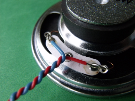
FIGURE 10-5 Wrap the wire around the speaker connections like this.
Figure 10-6 shows a close-up image of the breadboard layout taken at a different angle, which will help you to build the circuit.
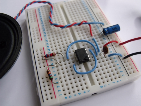
FIGURE 10-6 A close-up of the experiment around the 555 timer
Time to Experiment!
After you have built the circuit, you can connect the 4.5 volt battery to the circuit, as shown in Figure 10-7. The speaker should then make a loud buzzing noise.

FIGURE 10-7 Connect the battery to the circuit.
If this works, you could try to power the circuit from a 9 volt PP3 battery instead. The noise becomes a lot louder using a 9 volt battery—not as loud as a real car horn, but still fairly loud.
Further Experimentation
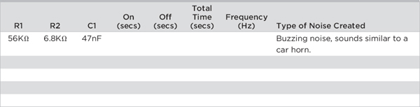
After you have finished annoying your parents with the horn, you can experiment further by changing the values of R1, R2, and C1 to see what effect this has on the type of noise that is generated. You can use Table 10-1 to record your results. The formula for calculating the astable time period and frequency of the output pulses is outlined in Chapter 5.
TABLE 10-1 Record the Results of Altering the 555 Timer’s Components
 HINT!
HINT!Try to use resistor values that are higher than 1KΩ.
Summary
In this chapter, you learned that the output from a pulsed 555 astable circuit can be used to drive a loudspeaker and create a noise. If you experimented further, you saw that by changing the frequency of the 555 timer, you can affect the frequency of the noise that is created by the speaker. You will be exploring this concept in more detail in Chapter 20.
..................Content has been hidden....................
You can't read the all page of ebook, please click here login for view all page.