CHAPTER 8
Which Way Now? Create Indicator Lights |  |
THIS SECTION OF THE BOOK IS DEDICATED TO a collection of experiments that attempt to emulate some of the features that you might find in a car. Before we build the first dashboard experiment, think about some of the features that you might find on a car’s dashboard.
Features of a Typical Car Dashboard
Look at Figure 8-1 and Table 8-1, which show and describe some of the features that you might find associated with a car’s dashboard.

FIGURE 8-1 A typical car dashboard
TABLE 8-1 Key Features of a Typical Car Dashboard
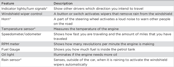
*The features that we are going to explore are identified by an asterisk.
In this chapter, you’ll build some experiments that relate to some of the features shown in Table 8-1.
 |
Experiment 5
Creating Indicator Lights |
In this experiment, you’ll create indicator lights that emulate turn signals on a car by using two LEDs as the left and right turn signal lights on a dashboard. You’ve probably noticed that when the turn signals in a car are activated, they make a clicking noise in time with the flashing lights. This is because the lights use a relay to switch the indicators, which makes this noise. Our circuit will also include a relay, which means that it will make the same type of clicking noise.
This experiment shows you how to flash an LED. If you suffer from epilepsy or are affected by flashing lights, this experiment is not for you.
What Is a Relay?
Before you take a look at the circuit and its operation, you should understand what a relay does and how it works. Relays are electronic switches that allow you to use a small current and voltage to switch a much larger current and voltage without the two different circuits mixing together. It does this by using an electromagnet to activate the switch. The electromagnet is created when a voltage is applied to the coil of the relay (see Figure 8-2). So, for example, in a car, the indicator lights will be drawing a fairly large current when they are switched on and off, compared to the control input current to the relay.
Here’s the circuit symbol for a typical double-pole, double-throw relay:

The “curly” connections on the symbol represent the coil of a relay, and the other connections are the switch contacts. A typical relay is shown in Figure 8-2; the electromagnetic coil is on the left, and the switch contacts are on the right.

FIGURE 8-2 Inside a typical relay
Following is some terminology you’ll come across when reading about or purchasing relays:
• Coil The coil will have a voltage rating, and you need to make sure that this is the same or slightly higher than the voltage of your control circuit.
• Switch contacts Contacts also have voltage and current ratings, which need to be higher than the voltage and current rating of your output circuit.
• Normally open (NO) This relates to the relay contacts; it means that when the relay is not energized, these contacts are not touching and are in an open position, creating an open circuit.
• Normally closed (NC) This relates to the relay contacts; it means that when the relay is not energized, these contacts are touching and are in a closed position, creating a short circuit.
• Single pole This relay will contain one set of switch contacts, a common connection, and a normally open and normally closed set of contacts.
• Double pole This relay will contain two sets of common, normally open and normally closed contacts.
 NOTE
NOTEDetails of other electronic components are explained in Chapter 3.
The Circuit Diagram
Now let’s take a look at the circuit diagram for the indicator lights shown in Figure 8-3.

FIGURE 8-3 The circuit diagram for the indicator lights
How the Circuit Works
This circuit is made up of four building blocks: power supply, input, control circuitry (555 astable pulse generator), and an output. This circuit is powered by four 1.5 volt AA batteries that are wired in series to create a 6 volt power supply. The “turn” switch (SW1) is the input for this circuit and makes one of the indicator LEDs illuminate. This control circuitry should be familiar to you if you have already read Chapter 5, which showed you how to make a flashing LED. The control circuit contains a 555 timer (IC1) configured in astable mode, and its on-off time is set by the values of R1, R2, and C1. The two LEDs (D1 and D2) and their series resistors (R3 and R4), in conjunction with the relay circuitry (RL1, D3 and D4), create the output part of this circuit.
Here’s how the circuit works: The 555 timer, which is set up in astable mode, creates a regular pulse output from pin 3 of this device. This pulsed signal activates the coil of the relay (RL1) and switches the relay on and off at a regular interval. The purpose of diode D4 is to make sure that only the positive signal from the 555 timer output reaches the coil of the relay. D3 acts as a flywheel (or flyback) diode, and it is important that this is included, because when the coil deactivates, a small current feeds out from the coil connections as the electromagnetic coil collapses. This small current could damage the 555 timer. Because diode D3 is included, it makes the current flow in a circle back through the coil until it eventually disappears; this stops the collapsing current reaching the 555 timer.
 INTERESTING FACT
A flyback diode is used to eliminate flyback, which is the sudden voltage spike experienced across an inductive load when its supply voltage is suddenly reduced or removed.
The Breadboard Layout
Using the components in the parts list, build the circuit by following the breadboard layout for the indicator lights, as shown in Figure 8-4.

FIGURE 8-4 The breadboard layout for the indicator lights
Figures 8-5 and 8-6 show close-up images of the breadboard layout that will help you to build the circuit.
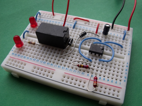
FIGURE 8-5 Close-up of the breadboard layout

FIGURE 8-6 Close-up with the relay removed slightly so that you can see the pin connections. Notice that the flat sides of the two LEDs are positioned toward the bottom of the board.
Time to Experiment!
Once you have built the circuit, connect the wire link that is acting as the switch (SW1) between the positive breadboard rail to the common connection of the left side of the relay, and then connect the battery to the circuit, as shown in Figure 8-7.

FIGURE 8-7 “Turning left”
Things You’ll Need
The components and equipment that you will need for this experiment are outlined in the following table. Prepare the items that you need before starting the experiment.
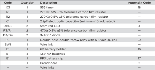 NOTE
NOTEThe Appendix Code column of the table refers to specific parts that I used in this experiment. Information about sourcing these parts is outlined in the Appendix.
You should find that the relay starts to click and the left-hand LED starts to flash on and off in time with the clicking noise, just like real turn signals in a car.
Now try moving the wire link from the left side of the relay to the right side. Figure 8-8 shows that this time the right-hand LED flashes on and off in time with the relay.

FIGURE 8-8 “Turning right”
Further Experimentation
Try a couple more experiments after you have finished playing with the indicator lights.
• See if you can modify the circuit so that both LEDs flash on and off in time with the relay, just like the hazard lights on a car.
• Once you have figured that one out, see if you can modify the circuit to make the LEDs flash on and off alternately, so that when the left LED flashes on, the right LED flashes off, and then when the left LED flashes off, the right LED flashes on.
 HINT!
HINT!Don’t forget that the relay contains both normally open and normally closed contacts.
Summary
In this chapter, you learned how to make a basic 555 timer circuit drive a relay, which could be used to drive LEDs or indicator lights with a higher current rating than the 555 timer can handle. You also discovered how a relay operates and how diodes can be used in a circuit to protect sensitive electronic circuitry from “flyback” from a relay coil.
..................Content has been hidden....................
You can't read the all page of ebook, please click here login for view all page.