
CHAPTER 5
You Have a Message! Make an LED Flash |  |
IN CHAPTER 4, YOU EXAMINED SOME of the features of a mobile phone and learned how to make an LED illuminate just like the charge indicator on a phone. Another useful phone feature is an LED indicator that flashes when you receive a text message or a phone call. The experiment in this chapter shows you one method of making an LED flash on and off using an inexpensive integrated circuit that requires only four other components.
How to Make an LED Flash
To make an LED flash on and off, you need to build a circuit that makes an electrical signal switch on and off. This type of circuit is known as a clock or astable circuit, and you can build one in many different ways. One of the easiest methods is to use a popular integrated circuit (IC) called the “555 timer,” and this is what you will be using in Experiment 2 in this chapter. A 555 timer IC has only eight pin connections and can be configured in two different modes: astable and monostable. This experiment explains how to build an astable circuit; the 555 timer’s monostable operation is described in future chapters.
 INTERESTING FACT
The 555 timer has been available since the early 1970s and due to its low cost and versatility it still remains a very popular integrated circuit today.
 NOTE
NOTEYou can read more about ICs and other components in Chapter 3.
First you need to learn about what an astable circuit is and what the electrical output signal looks like. Take a look at the diagram in Figure 5-1, which shows an astable waveform.

FIGURE 5-1 The output of an astable circuit looks like this.
 NOTE
NOTEA waveform shows what the voltage signal looks like in an electronic circuit. You use a special piece of measuring equipment called an oscilloscope to see a waveform.
This type of waveform is called a square wave and it shows how an electrical signal from an astable circuit switches on and off. The “high” part of the waveform represents a high voltage; normally this is the same as or almost the same as the battery voltage of the circuit. The “low” signal represents a low voltage, and normally this is 0 volts. This signal repeats itself in a never-ending sequence and produces an output signal that turns on and off and on and off and on and off.… Imagine that this output signal is connected to an LED, and you can see that it will cause the LED to switch on and off at a regular rate.
Look at the basic circuit diagram for a 555 timer that is configured in astable mode, as shown in Figure 5-2.
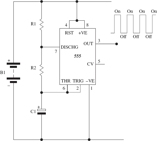
FIGURE 5-2 A basic 555 astable timer circuit and the output waveform
The 555 timer IC has eight pin connections, and you can see from the circuit diagram that nearly all of the pins are connected into the circuit. Pin 3 is the output connection and produces the “on-off-on-off” electrical signal that looks similar to the square wave shown in the corner of Figure 5-2. You will be connecting this output to an LED in the experiment that follows.
The speed of the output signal can be controlled and is configured by altering the values of the three components that you see in Figure 5-2: the two resistors (R1 and R2) and the capacitor (C1).
Before you build the experimental circuit, it is worth understanding how you can calculate the “On” and “Off” timings of this type of astable circuit. A few key formulas are associated with this mode of operation, and these are outlined here. Read these formulas in conjunction with Figures 5-1 and 5-2:
• The on time of the timer output (high output) is calculated by using this formula:
On (measured in seconds) = 0.693 × (R1 + R2) × C1
• The off time of the timer (low output) is calculated by using this formula:
Off (measured in seconds) = 0.693 × R2 × C1
• The total time period for one cycle (T) is therefore
T1 + T2
• The frequency of oscillation (F) is expressed in Hertz (Hz):
F = 1 / T
We will be using these formulas shortly.
NOTEFrequency is the number of times T1 + T2 occurs every single second.
 |
Experiment 2
Making an LED Flash |
This experiment shows you how easy it is to use an astable 555 timer IC as a control building block to enable you to flash an LED on and off. You will also be experimenting with various component values to see what effect this has on the way that the LED flashes on and off.
This experiment shows you how to make an LED flash. If you suffer from epilepsy or are affected by flashing lights, this experiment is not for you!
The Circuit Diagram
Now that you understand how to make an astable circuit, take a look at the circuit diagram for this experiment, which is shown in Figure 5-3.

FIGURE 5-3 The circuit diagram for the LED flasher
The circuit diagram looks very similar to the diagram in Figure 5-2, except it now includes some specific component values for R1, R2, and C1, which creates a suitable clock output on pin 3 of the 555 timer (IC1). Pin 3 is also connected to an LED (D1) via a series resistor (R3).
NOTERead more about calculating LED series resistors in Chapter 4.
How the Circuit Works
This circuit is made up of three building blocks: power supply, control circuitry, and output. This circuit is powered by three 1.5 volt AA batteries that are all wired in series to generate a 4.5 volt supply (B1). The 555 timer (IC1) and its associated timing components R1, R2, and C1 create the control circuitry in this experiment. The LED (D1) and resistor (R3) form the output part of this circuit, and if you have built the experiment in Chapter 4 you will have learnt about this building block already.
Having understood the operation of the 555 timer (IC1) as described earlier, you should be able to figure out how the circuit works already. The only addition to the 555 astable timer circuit is the LED (D1) and its series resistor (R3), which allow you to see the astable waveform output from pin 3.
The Breadboard Layout
Using the breadboard, build the circuit following the layout shown in Figure 5-4.
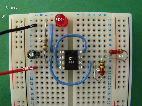
FIGURE 5-4 The breadboard layout for the LED flasher
Things You’ll Need
The components and equipment that you will need for this experiment are outlined in the following table. Locate and prepare the items that you need before starting the experiment.
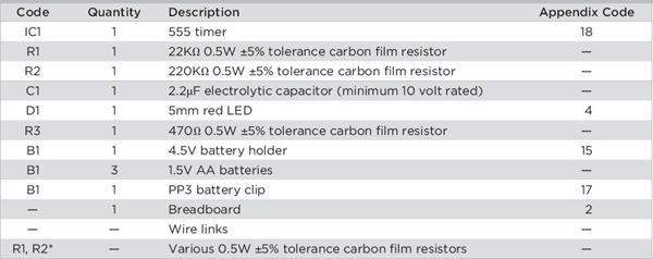
*See the “Further Experimentation” instructions at the end of this chapter.
NOTEThe Appendix Code column of the table refers to specific parts that I used in this experiment. Information about sourcing these parts is outlined in the Appendix.
NOTERefer to Chapter 3 for building breadboard layouts and fault-finding guidelines.
Notice in Figure 5-4 how the negative lead of the battery is connected to the flat side of the LED and the negative side of capacitor C1.
It is important that you connect the electrolytic capacitor (C1) the correct way round in the circuit; if you don’t, it could leak or explode!
Figures 5-5 and 5-6 show some close-up views of the breadboard layout, taken at different angles, which will help you build the circuit.

FIGURE 5-5 Notice the position of the semicircle of IC1 and the flat side of the LED.

FIGURE 5-6 See the markings on capacitor C1, which identify the negative and positive leads.
Time to Experiment!
Once you are happy with your breadboard layout, connect the 4.5 volt battery to the battery clip; the LED should flash on and off at a steady rate. Your finished experimental circuit layout should look like Figure 5-7.

FIGURE 5-7 Connecting the 4.5 volt battery will cause the LED to flash on and off like a mobile phone message indicator.
If your circuit works, the LED will flash on and off at a steady rate until the batteries are removed or they run dry. If the LED does not flash on and off, you need to remove the battery immediately and check that your breadboard layout matches the layout shown in the figures. Also make sure that IC1, the capacitor C1, and the LED D1 are fitted in the correct orientation; otherwise, the circuit will not work correctly.
You can calculate the astable timings for this circuit by substituting the component values into the formulas described earlier in the chapter.
How to Convert Capacitor and Resistor Values into Numbers That You Can Use in the Formulas
You need to convert the capacitor value to farads and the resistor value to ohms when using the astable formulas. You can use the following calculations to help you do this.
Capacitance
• To convert picofarads (pF) to farads, divide the pF value by 1,000,000,000,000.
• To convert nanofarads (nF) to farads, divide the nF value by 1,000,000,000.
• To convert microfarads (μF) to farads, divide the μF value by 1,000,000.
Resistance
• To convert kilo-ohms (KΩ) to ohms (Ω), multiply the KΩ value by 1000.
• To convert mega-ohms (KΩ) to ohms (Ω), multiply the MΩ value by 1,000,000.
Here’s how to calculate the LED on time:
On = 0.693 × (R1 + R2) × C1
On = 0.693 × (22KΩ + 220KΩ) × 2.2μF
On = 0.693 × (22,000Ω + 220,000Ω) × 0.0000022F
LED On time = 0.37 seconds
Here’s how to calculate the LED off time:
Off = 0.693 × R2 × C1
Off = 0.693 × 220KΩ × 2.2μF
Off = 0.693 × 220,000Ω × 0.0000022F
LED Off time = 0.34 seconds
Here’s how to calculate the frequency of the LED flash. First, the total time period for one cycle:
T = T1 + T2
T = 0.37 + 0.34 = 0.71 seconds
Then you can calculate the frequency of oscillation:
F = 1 / T
F = 1 / 0.71
The LED flashing frequency = 1.4 Hz
This means that the on/off cycle of the LED occurs roughly one-and-a-half times every second.
Further Experimentation
Try replacing the two resistors R1 and R2 with different values to see what effect this has on the flash rate of the LED. Make sure that you remove the battery from the breadboard before making any changes to these component values.
Do not alter the value of resistor R3, because this could damage the LED.
You could also try altering the value of the capacitor (C1) to see what effect this has on the LED flash rate. If you use an electrolytic capacitor, make sure that you connect it the correct way around in the circuit so that the negative lead is connected to pin 1 of IC1.
 HINT!
HINT!If you alter the component values and the LED looks as though it is not flashing, try to calculate on and off timings using the formulas. You might find that the LED is actually flashing at such a fast rate that it looks like the LED is permanently illuminated to the human eye!
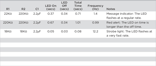
Table 5-1 shows a few example component values to get you started. The table also shows some blank spaces so that you can write down some of the component values that you find useful in your experiments.
TABLE 5-1 Component Table for Useful Astable Timings
Summary
In this chapter, you learned how to use a 555 timer IC to flash an LED on and off. Can you think of any possible uses for this circuit? Can you think of electronic products that you have seen that use this type of flashing LED effect? You will see this circuit again in later experiments, which might give you some other ideas.
..................Content has been hidden....................
You can't read the all page of ebook, please click here login for view all page.