
You don’t hear much about code overlays today. With today’s seemingly unlimited virtual memory in desktops and servers, applications often don’t check for the risk of running out of memory. Yet in the early days of the mainframe’s using core memory and the fledgling IBM PC, running out of memory was a frequent concern. Overlays were instrumental in doing more with less.
Overlays continue to have a role today in microcontrollers because of those products’ own memory limits. Embedded products may begin with a selected microcontroller, only to discover later that the software won’t fit. If this happens late in the product development cycle, a solution for using the existing MCU (Micro Controller Unit) must be found or software features must be dropped.
The designer may know that some sections of code are not needed often. A full-featured BASIC interpreter, for example, could swap in a code segment to renumber the program only when it is needed. The rest of the time, that code would remain unused and would not need to be resident.
There isn’t much information available online about how to use GCC overlays. 1 There is plenty of discussion about load scripts, but specifics about the rest are usually left as an exercise for the reader. This chapter is dedicated to a full demonstration of a working example. This demo will swap overlays from the SPI flash chip into an SRAM overlay region, where the code will be executed. Given that these flash chips offer 4 MB or 8 MB of code storage, your imagination is the limit when it comes to larger applications on the STM32.
The Linker Challenge
In application development, your imagination leads you to write C code that is translated by the compiler into one or more object files (*.o). If the application is small enough, you link it into one final *.elf file, which is designed to fit the available flash memory in the MCU. For the STM32, the st-flash utility needs a memory image file, so the following build step converts the .elf file to a binary image first:
$ arm-none-eabi-objcopy -Obinary main.elf main.binThen, the image file main.bin is uploaded to flash at address 0x8000000:
$ st-flash write main.bin 0x8000000That is the typical link process, but how do you create overlays? Let’s get started with the Winbond demo project . Go to the following subdirectory:
cd ~/stm32f103c8t6/rtos/winbondThen, perform the following:
$ make clobber
$ make
This will force recompile that project, and at the end of it all the link step will look something like the following (the lines are broken up to fit the page for readability):
arm-none-eabi-gcc --static -nostartfiles -Tstm32f103c8t6.ld
  -mthumb -mcpu=cortex-m3 -msoft-float -mfix-cortex-m3-ldrd
  -Wl,-Map=main.map -Wl,--gc-sections main.o rtos/heap_4.o
  rtos/list.o rtos/port.o rtos/queue.o rtos/tasks.o
  rtos/opencm3.o -specs=nosys.specs -Wl,--start-group
  -lc -lgcc -lnosys -Wl,--end-group
  -L/Users/ve3wwg/stm32f103c8t6//rtos/libwwg -lwwg
  -L/Users/ve3wwg/stm32f103c8t6/libopencm3/lib
  -lopencm3_stm32f1 -o main.elf
This whole linking process is governed by the link script specified by the option -Tstm32f103c8t6.ld. When there is no -T option given on a Linux build command, for example, one will be assumed by default. But let’s examine the file provided in the Winbond project.
MEMORY Section
The linker script contains a MEMORY section at the beginning that looks like the following:
MEMORY
{
        rom (rx) :  ORIGIN = 0x08000000, LENGTH = 64K
        ram (rwx) : ORIGIN = 0x20000000, LENGTH = 20K
}
This part of the load script declares two memory regions. These are regions that we are going to load code into (rom) or allocate space for (ram). If you are building large applications, I would advise you to change that rom size to 128K in the linker script and use the open-sourced st-link command to flash it using the --flash=128k option (doing a “make bigflash” will specify this option from the provided Makefile). As noted before, the STMF103C8T6 seems to support 128K despite its claim that only 64K exists.
After expanding rom to 128K, the MEMORY section should look like the following:
MEMORY
{
        rom (rx) :  ORIGIN = 0x08000000, LENGTH = 128K
        ram (rwx) : ORIGIN = 0x20000000, LENGTH = 20K
}
The optional attributes within brackets, like (rwx), describe the intended uses for the memory region (read, write, and execute). GCC documentation says that they are supported for backward compatibility with the AT&T linker but are otherwise only checked for validity. 2
The ORIGIN = 0x20000000 parameter indicates where the block of ram memory physically resides. The LENGTH parameter is the size in bytes. Let’s compare this notion of memory with the basic physical memory map of the MCU, shown in Figure 9-1.
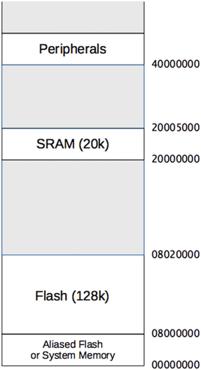
Figure 9-1 Basic STM32F103C8T6 memory layout (addresses in hexadecimal)
The memory that appears at the region starting at 0x00000000 depends upon the BOOT0 and BOOT1 switches. Normally, the setting BOOT0=0 is used, causing the flash memory to appear at location zero as well as at 0x08000000. This allows the MCU startup code to be the programmed flash memory.
At the higher address of 0x20000000 we find the static ram (SRAM). The size of this memory region is 20K for the STM32F103C8T6. Now, let’s look at the remainder of the load script to see how it works.
Entry
The main driver of the load process is going to be the SECTIONS region of the file that we’ll examine next, but there are two entries I’ll discuss first. These are the ENTRY and EXTERN keywords:
ENTRY(reset_handler)
EXTERN (vector_table)
These entries do not appear in the MEMORY or SECTIONS areas of the load script but rather stand alone. The ENTRY keyword names the routine that is passed control at startup. The EXTERN keyword identifies a data area that will define the initial interrupt vector. With the environment being used, these will be supplied from the libopencm3 static library from a module named vector.o as follows:
~/stm32f103c8t6/libopencm3/lib/libopencm3_stm32f1.aIf you need to change the startup in any way, or are just curious, view the libopencm3 module here:
~/stm32f103c8t6/libopencm3/lib/cm3/vector.cBecause the symbol reset_handler is referenced by the ENTRY keyword , the vector.o module is loaded (unless you have supplied one of your own). This saves you from having to define all of the initialization required. When the reset handler has performed its setup, it will then call upon your main() program .
Sections
This is where things get interesting in the load script. In general terms, you’ll find that this section appears like the following:
SECTIONS
{
    .text : {
        *(.vectors)     /* Vector table */
        *(.text*)       /* Program code */
        . = ALIGN(4);
        *(.rodata*)     /* Read-only data */
        . = ALIGN(4);
    } >rom
    ...etc...
}
I’ve trimmed some of the content so that you can focus on the essentials. From the snippet shown you can see that comments exist in the load script in C language form; for example, /* comment */. Don’t let the remainder of the odd-looking syntax put you off. Let’s break it down.
    .text : {
        *(.vectors)     /* Vector table */
        *(.text*)       /* Program code */
        . = ALIGN(4);
        *(.rodata*)     /* Read-only data */
        . = ALIGN(4);
    } >rom
A specific section begins with a name, which is .text in this example. Section names can be composed of almost any character, though odd characters or spaces must be quoted using ("). Otherwise, a symbol is expected to be surrounded by white space.
The section declared is named .text and is followed by a colon (:) and then a starting and ending curly brace. After the closing brace, we see >rom. This specifies that the input described between the curly braces will be placed into the MEMORY region named rom (remember that MEMORY section?)
What appears between the braces describes input and symbol calculations. Let’s look at one input example first:
*(.vectors)What this means is that any input file (*) containing an object file section named .vectors is to be included in the output section being defined (in this case, .text).
Keep in mind that there are two kinds of sections involved:
Input object sections (like .vectors in the example)
Output sections (like .text in the example)
The initial asterisk names any file but could specify filenames instead. For example, the following two examples are possibilities:
        *.o(.vectors)        /* any .o file having .vectors */
        special.o(.vectors)  /* special.o having a .vectors section */
If we strip the example down to just the inputs, we would have the following:
    .text : {
        *(.vectors)     /* Vector table */
        *(.text*)       /* Program code */
        *(.rodata*)     /* Read-only data */
    } >rom
Boiled down from the preceding example, then, we are loading from any input file, from object file sections .vectors, .text, or .rodata. These will be loaded into the memory region named rom. Still with me?
Now, what about that other voodoo? The symbol dot (.) is used as the current location within the section. This practice undoubtedly comes from the assembler’s use of the dot for the “location assignment counter.” Within the link script, the dot symbol serves a similar purpose:
    .text : {
        *(.vectors)     /* Vector table */
        *(.text*)       /* Program code */
        . = ALIGN(4);
        *(.rodata*)     /* Read-only data */
        . = ALIGN(4);
    } >rom
The value of the dot at the middle (after .text) is the location at the end of the .text section (at that point in the link), but rounded up to the 4-byte word boundary (due to the use of special function ALIGN(4)). In this case, the current location is bumped up to the next aligned location. This is invoked a second time after the loading of input section .rodata (read-only data) so that if anything else is loaded into .text it will be aligned. Now, the mystery has been revealed!
Note that expressions like those involving dot are ended with a semicolon (;). Symbols can also be calculated in the same manner. For example, in the same script, and between section declarations, you’ll find the following:
...} >rom. = ALIGN(4);_etext = .;
Because these last two lines are expressions appearing outside of the section definition (that is loading into rom), dot here will refer to the last location referenced (inside of rom). From this, we see that dot is aligned to the next word boundary and then assigned to a symbol _etext. Arithmetic is allowed in these expressions, if required. The symbol _etext in your program will then have the address of the first byte past the end of your read-only region in flash (rom).
PROVIDE
The PROVIDE keyword , used within a linker script, gives you the ability to define a symbol if it is needed (referenced). If the symbol isn’t referenced, then its definition is withheld from the link to avoid symbol conflicts. The following will be found in your load script:
PROVIDE(_stack = ORIGIN(ram) + LENGTH(ram));This statement says, provide symbol _stack if it is referenced. Calculate it as the starting address of memory region ram plus the length of the memory region. In other words, the starting address of a stack, which grows downward in the available SRAM region.
Relocation
As part of directing the linker, one issue that comes up is the need to have the linker put some stuff in flash memory, but to relocate references to that stuff as if it existed in SRAM. To look at this another way, we will be using some data in SRAM, but it will not live in SRAM until some startup code copies it there. Here is an example from your load script:
    .data : {
        _data = .;
        *(.data*)       /* Read-write initialized data */
        . = ALIGN(4);
        _edata = .;
    } >ram AT >rom
Here we define two symbols:
_data (start of data)
_edata (end of data)
Of particular interest is the last line:
} >ram AT >romAs you probably have guessed, this means that the symbols should be defined as if they were in ram (SRAM), but they will be written into the flash section (rom) instead. The initialization code within the module vector.o discussed earlier will copy this data from flash into the final SRAM location before main() is called.
This affects the relocation of any symbol references. If you had a static int constant, for example, that was not declared const, then it would be destined for SRAM. The address of that int will be set up by the linker to be somewhere in SRAM (address 0x20000000 to 0x20004FFF). However, the int value itself will be loaded into flash memory (somewhere between 0x08000000 and 0x0801FFFF). Startup initialization must copy it to SRAM to make it valid.
Keep this in mind as we turn our attention to overlays.
Defining Overlays
Now that you’re armed and dangerous, let’s get started with using the linker to define overlays. Change to the project directory overlay1:
$ cd ~/stm32f103c8t6/rtos/overlay1In this project subdirectory, we have a modified version of the linker script stm32f103c8t6.ld that we’ll be looking at.
The first thing of interest is that we’ve declared four memory regions instead of the usual two:
MEMORY{rom (rx) : ORIGIN = 0x08000000, LENGTH = 128Kram (rwx) : ORIGIN = 0x20000000, LENGTH = 18K/* Overlay area in RAM */ovl (rwx) : ORIGIN = 0x20004800, LENGTH = 2K/* Give external flash its own storage */xflash (r) : ORIGIN = 0x00000000, LENGTH = 4M}
The ram region has been shortened by 2K to leave room for the new SRAM overlay region named ovl. The memory addressed from 0x20004800 to 0x20004FFF is reserved to execute our overlay code.
The other new region, named xflash, is defined so that the linker can emit code that will reside in our external SPI flash. There will be more about this later.
The remainder of the linker script magic can be found later in the file as follows:
    OVERLAY : NOCROSSREFS {
        .fee {
            .overlay1_start = .;
            *(.ov_fee)              /* fee() */
            *(.ov_fee_data)         /* static data for fee() */
        }
        .fie { *(.ov_fie) }         /* fie() */
        .foo { *(.ov_foo) }         /* foo() */
        .fum { *(.ov_fum) }         /* fum() */
    } >ovl AT >xflash
    PROVIDE (overlay1 = .overlay1_start);
Let’s now pick this apart. The OVERLAY keyword tells the linker to load all sections into the overlay section in an overlapping manner. In the example shown, the sections .fee, .fie, .foo, and .fum will all start at the same location. Given that >ovl puts this code into the overlay memory region, they will all have a starting address of 0x20004800. Of course, it is understood that not all of them can reside in that space at the same time.
The symbol .overlay1_start captures the starting address of the overlay region and is eventually passed into the PROVIDE statement so that symbol overlay1 will contain the overlay starting address 0x20004800. This symbol can be used within the C program.
The keyword NOCROSSREFS provides another important linker feature. It would be unworkable for one overlay to call upon or reference another overlay in the same region. Only one overlay can reside in a region at one time. Calling function fie() from fee() would be disastrous. The NOCROSSREFS keyword instructs the linker to treat this scenario as an error.
Finally, note the following line:
} >ovl AT >xflashThis directs the linker to relocate the code as if it runs at the overlay (ovl) address (in SRAM) but to place that overlay code into the memory region xflash instead. The xflash memory region will require a bit of special handling later on, but we need the linker to do this bit of trickery first.
An important concept here is that whatever goes into xflash is destined for the Winbond SPI flash device, starting at SPI flash address zero. This was established by the ORIGIN keyword in the following:
xflash (r) : ORIGIN = 0x00000000, LENGTH = 4MOverlay Code
The section declared as .fee consists of two input sections, which come from the .ov_fee and .ov_fee_data sections. This provides an example of declaring code and data within the same overlay, presented in Listing 9-1.
Listing 9-1 The fee() Function Overlay Declaration
0027: int fee(int arg) __attribute__((noinline,section(".ov_fee")));
      ...
0115: int
0116: fee(int arg) {
0117:   static const char format[] // Placed in overlay
0118:       __attribute__((section(".ov_fee_data")))
0119:       = "***********
"
0120:         "fee(0x%04X)
"
0121:         "***********
";
0122:
0123:   std_printf(format,arg);
0124:   return arg + 0x0001;
0125: }
To tell the compiler that the fee() function is to go to section .ov_fee (in the object file), we must use the GCC __attribute__ keyword (line 27). This attribute can only be specified in the function prototype.
The noinline keyword prevents GCC from inlining the code for fee(). This is especially important for our demo because the function is small enough to be inlined at the point of the call by GCC.
The second argument, section(".ov_fee"), names the section that our fee() function code should be written to in the main.o object file. The read-only data declared in lines 117 to 121 is specified to go into section .ov_fee_data. The compiler insists that this data section be different from the function code.
The remaining functions are simpler but apply the same idea. Listing 9-2 illustrates the fie() overlay function .
Listing 9-2 The fie() Function Overlay Code
0028: int fie(int arg) __attribute__((noinline,section(".ov_fie")));
      ...
0131: int
0132: fie(int arg) {
0133:
0134:   std_printf("fie(0x%04X)
",arg);
0135:   return arg + 0x0010;
0136: }
Again, the overlay is named in the function prototype (line 28). The declaration of the function in lines 131 to 136 is per usual. Note that unlike fee(), the string constant used in line 134 will become part of the non-overlay code in the rom region here.
Overlay Stubs
Before the overlay code can be executed, the code from the SPI flash must be copied into the overlay area in SRAM. For this reason, each of the overlay functions uses a “stub function ” and overlay manager, like the one shown in Listing 9-3.
Listing 9-3 Stub Function for fee()
0164: static int
0165: fee_stub(int arg) {
0166:   int (*feep)(int arg) = module_lookup(&__load_start_fee);
0167:
0168:   return feep(arg);
0169: }
Our fee() function takes an int argument and returns an int value. Consequently, the stub function must do the same. However, before we can call the overlay function, the function module_lookup() is invoked to see if it is already in the ovl (overlay) region and, if not, to copy it there now. Finally, we need to know its function address so that we can call it, which the module_lookup() function will return.
Overlay Manager
An overlay manager of some sort is usually required, especially when multiple overlay regions are used. Our demo program sets up an overlay table using an array of struct s_overlay:
0036: typedef struct {
0037:   short          regionx; // Overlay region index
0038:   void           *vma;    // Overlay's mapped address
0039:   char           *start;  // Load start address
0040:   char           *stop;   // Load stop address
0041:   unsigned long  size;    // Size in bytes
0042:   void           *func;   // Function pointer
0043: } s_overlay;
For this demo, only one overlay region is used; therefore, regionx is always the index value zero. However, if you were to support three overlay regions, for example, this index could be a value of 0, 1, or 2. It is used to track which overlay is currently in the overlay region so that it is not always necessary to copy in the code.
The member vma is the overlay’s mapped address (its SRAM location when executed). Members start and stop are the external flash addresses (from region xflash) that we need to load. Member size will have the calculated overlay size in bytes, while the final member func will contain the SRAM function pointer.
Are you still mulling over the values of start and stop right now? Give yourself points if you are. The question is how does the demo program locate the SPI flash code to load?
VMA and Load Addresses
The VMA (virtual memory address ) and the load address for overlays are different. We have arranged for the overlay code and data to be written into the xflash memory area. Those load addresses will start from zero, since that is where the SPI flash addresses will begin. The VMAs for that code will be calculated for the overlay area in SRAM.
This is pointed out because we cannot use the VMAs for our overlay table as they map to the same region of SRAM. Some of the function pointers might even be the same. However, the load addresses (from SPI flash) will be unique. This permits us to use them as identifiers in our overlay table.
In the demo program a macro is used for programming convenience:
0048: #define OVERLAY(region,ov,sym)
      { region, &ov, &__load_start_ ## sym, &__load_stop_ ## sym, 0, sym }
Because we are using only one overlay region, the region parameter will always be zero. But if you choose to add another, then you can supply the index as parameter 1.
The ov parameter refers to the overlay’s starting address . The sym parameter allows us to specify the overlay function . Let’s expand on this after we illustrate the demo program’s table:
0056: // Overlay table:
0057: static s_overlay overlays[N_OVLY] = {
0058:   OVERLAY(0,overlay1,fee),
0059:   OVERLAY(0,overlay1,fie),
0060:   OVERLAY(0,overlay1,foo),
0061:   OVERLAY(0,overlay1,fum)
0062: };
In the demo table’s contents, the symbol overlay1 is referenced as the symbol describing the overlay’s starting address in SRAM. The load script defines the start of that region as address 0x20004800 (for 2K bytes). Recall that the symbol was defined in the load script as follows:
PROVIDE (overlay1 = .overlay1_start);Looking closer at one table entry,
0058: OVERLAY(0,overlay1,fee),we see that argument three is supplied as fee. The macro expands into the following line:
{ 0, &overlay1, &__load_start_fee, &__load_stop_fee, 0, fee }Where do the symbols __load_start_fee and __load_stop_fee come from? These are automatically generated by the linker when the section .fee is processed. These two lines can be found in your main.map file that is written by the linker:
0x0000000000  PROVIDE (__load_start_fee, LOADADDR (.fee))
0x0000000045  PROVIDE (__load_stop_fee, (LOADADDR (.fee) + SIZEOF (.fee)))
From this we learn that the .fee section is loaded at address zero in the xflash (SPI flash) memory region and is 0x45 bytes (69 bytes) long.
Linker Symbols in Code
One thing that trips up new players when using linker symbols like __load_start_fee, for example, is that they try to use the values at those addresses rather than the addresses themselves. Let’s clear this up with a code example:
extern long __load_start_fee;Which is the correct usage to access the linker symbol __load_start_fee? Is it:
__load_start_fee (the value), or
&__load_start_fee (the address) ?
I’ve already given it away. Solution 2 is the correct answer, but why?
Solution 1 would imply that that the linker put 4 bytes of storage at the address of __load_start_fee, containing the symbol’s value (which is an address). But the linker defines a symbol’s value as an address, so no storage is allocated.
Returning to the overlay table that is used by the overlay manager, we see that the structure members of the first entry are populated as follows:
0036: typedef struct {
0037:   short          regionx;  // 0 (overlay index)
0038:   void           *vma;     // &overlay1
0039:   char           *start;   // &__load_start_fee
0040:   char           *stop;    // &__load_stop_fee
0041:   unsigned long  size;     // 0 (initially)
0042:   void           *func;    // A pointer inside SRAM
0043: } s_overlay;
This entry then defines the address of the SRAM overlay area in struct member vma using the linker-provided address &overlay1. Likewise, members start and stop also use linker-provided addresses. The size member will be calculated once at runtime. Finally, the member func is provided the value fee. What? What’s going on with that?
Because the compiler knows that fee is the symbol of a function entry point of the function fee(), the simple reference to the symbol serves as the address. This linker-symbol mambo can be a little confusing.
Overlay Manager Function
Let’s finally present the overlay function (Listing 9-4). The value that is passed in as the argument module is the overlay load address; for example, &__load_start_fee. This is the address that the linker placed the overlay code in, which will come from the SPI flash.
Listing 9-4 The Overlay Manager Function
0071: static void *
0072: module_lookup(void *module) {
0073:   unsigned regionx;            // Overlay region index
0074:   s_overlay *ovl = 0;          // Table struct ptr
0075:
0076:   std_printf("module_lookup(%p):
",module);
0077:
0078:   for ( unsigned ux=0; ux<N_OVLY; ++ux ) {
0079:       if ( overlays[ux].start == module ) {
0080:           regionx = overlays[ux].regionx;
0081:           ovl = &overlays[ux];
0082:           break;
0083:       }
0084:   }
0085:
0086:   if ( !ovl )
0087:       return 0;                // Not found
0088:
0089:   if ( !cur_overlay[regionx] || cur_overlay[regionx] != ovl ) {
0090:       if ( ovl->size == 0 )
0091:           ovl->size = (char *)ovl->stop - (char *)ovl->start;
0092:       cur_overlay[regionx] = ovl;
0093:
0094:       std_printf("Reading %u from SPI at 0x%04X into 0x%04X
",
0095:           (unsigned)ovl->size,
0096:           (unsigned)ovl->start,
0097:           (unsigned)ovl->vma);
0098:
0099:       w25_read_data(SPI1,(unsigned)ovl->start,ovl->vma,ovl->size);
0100:
0101:       std_printf("Returned...
");
0102:       std_printf("Read %u bytes: %02X %02X %02X...
",
0103:           (unsigned)ovl->size,
0104:           ((uint8_t*)ovl->vma)[0],
0105:           ((uint8_t*)ovl->vma)[1],
0106:           ((uint8_t*)ovl->vma)[2]);
0107:   }
0108:   return ovl->func;
0109: }
Lines 78 to 84 perform a linear search of the table looking for a match on the module address (matching occurs in line 79). If a match is found, the index of the entry is saved in regionx (line 80). Then, the address of the overlay table entry is captured in line 81 in ovl before breaking out of the loop.
If the loop was exited without a match, 0 (null) is returned in line 87. This is fatal if used as a function call and indicates a bug in the application.
Line 89 checks to see if the overlay is valid and is already loaded or not. If the overlay must be read in, lines 90 to 107 are executed to make the overlay ready for use. If the overlay size is not yet known, it is calculated and saved in the table at lines 90 to 91. Line 92 tracks which overlay is currently loaded. Line 99 performs the SPI read from the flash device from the device’s flash address ovl->start into the overlay SRAM memory at ovl->vma for ovl->size bytes.
With the overlay code loaded, the function pointer is returned in line 108.
Overlay Stubs
To ease the use of overlays, a stub function is normally used as a surrogate so that it can be called like a regular function. Listing 9-5 illustrates the stub function for the overlay fee().
Listing 9-5 The fee() Stub Function
0164: static int
0165: fee_stub(int arg) {
0166:   int (*feep)(int arg) = module_lookup(&__load_start_fee);
0167:
0168:   return feep(arg);
0169: }
The stub function merely calls the overlay manager with the correct symbol (&__load_start_fee in this case). Once it has the function pointer captured in feep, it is safe to make the function call because the overlay manager can load the code when necessary. The function pointer feep allows the function to be invoked with the correct arguments and return the overlay’s return value.
Demonstration
The demonstration program main.c (Listing 9-6) performs some initialization for SPI and for USB. Then, task1 is launched to perform USB terminal I/O.
Listing 9-6 Initialization
0247: int
0248: main(void) {
0249:
0250:   rcc_clock_setup_in_hse_8mhz_out_72mhz(); // Use this for "blue pill"
0251:   rcc_periph_clock_enable(RCC_GPIOC);
0252:   gpio_set_mode(GPIOC,GPIO_MODE_OUTPUT_2_MHZ,
            GPIO_CNF_OUTPUT_PUSHPULL,GPIO13);
0253:
0254:   usb_start(1);
0255:   std_set_device(mcu_usb);               // Use USB for std I/O
0256:
0257:     w25_spi_setup(SPI1,true,true,true,SPI_CR1_BAUDRATE_FPCLK_DIV_256);
0258:
0259:   xTaskCreate(task1,"task1",100,NULL,configMAX_PRIORITIES-1,NULL);
0260:   vTaskStartScheduler();
0261:   for (;;);
0262:   return 0;
0263: }
To rebuild this project from scratch, perform:
$ make clobber
$ make
But don’t flash your STM32 just yet.
Extracting Overlays
Before you can exercise your overlays, you have to get that overlay code loaded onto your W25Q32 flash device. Recall that we placed the overlay code in linker memory region xflash? Now we have to get that from the linker output and load it into the SPI device.
You may have noticed that the make command performed some extra steps in this project:
arm-none-eabi-gcc --static -nostartfiles -Tstm32f103c8t6.ld ... -o main.elf
for v in fee fie foo fum ; do
    arm-none-eabi-objcopy -O ihex -j.$v main.elf $v.ov ;
    cat $v.ov | sed '/^:04000005/d;/^:00000001/d' >>all.hex ;
done
arm-none-eabi-objcopy -Obinary -R.fee -R.fie -R.foo -R.fum main.elf main.bin
After the normal link step (arm-none-eabi-gcc), you see some additional shell commands being issued as part of a for loop. For each of the overlay sections (fee, fie, foo, and fum) a pair of commands is issued, as follows:
    arm-none-eabi-objcopy -O ihex -j.$v main.elf $v.ov
    cat $v.ov | sed '/^:04000005/d;/^:00000001/d' >>all.hex
The first command extracts the named section in Intel hex format output (-O ihex). If variable v is the name fee, section .fee (-j.fee) is extracted to the file named fee.ov. The sed command that follows just strips out type 05 and 01 records from the hex file that we don’t need and concatenates them all to the file all.hex.
The last step requires that we remove the overlay sections from main.elf so that the final image file doesn’t include the overlays. If we left them in, then st-flash would try to upload that to the STM32 and fail.
arm-none-eabi-objcopy -Obinary -R.fee -R.fie -R.foo -R.fum main.elf main.binThis command writes the image file main.bin (option -Obinary) and removes sections .fee, .fie, .foo, and .fum using the -R option. The main.bin is the image file that the st-flash command will use for the upload.
Tip
To make it easier to access from minicom, you may want to copy the file all.hex to your home directory or /tmp.
Upload Overlays to W25Q32
To upload the overlay code to the Winbond flash chip, use the project winbond to do it, from the project directory :
cd ~/stm32f103c8t6/rtos/winbondRebuild that project and flash it to your STM32:
$ make clobber
$ make
$ make flash
Before starting minicom , however, make sure that you have the following command installed on your system:
$ type ascii-xfr
ascii-xfr is /usr/local/bin/ascii-xfr
This is normally installed with minicom and may be installed in a different directory on your system. If not found, you’ll need to fix that (maybe re-install minicom).
Then, disconnect the programmer and plug in the USB cable. Start up minicom:
$ minicom usbWith minicom running, check your upload settings next. Press Esc-O (or use Control-A O if necessary) quickly to bring up a menu, then select “File Transfer Protocols.” If a menu didn’t pop up, then try again. There cannot be much delay between typing the Escape/Control-A key and the letter O (oh).
Look for the protocol name “ascii,” which is usually at the end of the list. Type the letter for the entry (letter I on my system), and press Return to enter the “Program” input area. Modify that entry to look as follows:
/usr/local/bin/ascii-xfr -n -e -s -l75The most important option is the -l75 (lowercase el), which causes a 75 ms delay after each text line is sent. Without a reasonable delay, the uploads will fail. You probably should also set the other options as shown.
The remaining option flags are known to work:
Name U/D FullScr IO-Red. Multi
Y    U    N       Y       N
Press Return to move through the list of input settings. Press Return one more time to pop back to the main menu, then select “Save setup as USB.” You should now be able to use the minicom session to upload the all.hex file.
Once out of the menu, or in minicom initially, press Return to cause the program to present a menu :
Winbond Flash Menu:0 ... Power down1 ... Power ona ... Set addressd ... Dump pagee ... Erase (Sector/Block/64K/Chip)i ... Manufacture/Device infoh ... Ready to load Intel hexj ... JEDEC ID infor ... Read bytep ... Program byte(s)s ... Flash statusu ... Read unique IDw ... Write Enablex ... Write protectAddress: 000000:
Check that your SPI flash is responding and erase it if necessary.
: WSR1 = 02 (write enabled)SR2 = 00: EErase what?s ... Erase 4K sectorb ... Erase 32K blockz ... Erase 64K blockc ... Erase entire chipanything else to cancel: ssector erased, starting at 000000Sector erased.:
Here, our address is still zero, but if not set it to zero now:
: AAddress: 0Address: 000000:
Enable write again (erase disables it) and then prepare to upload the hex file :
: WSR1 = 02 (write enabled)SR2 = 00: HReady for Intel Hex upload:00000000 _
Now press Escape-S (or Control-A S) to pop up the Upload menu and choose "ascii":
           +-[Upload]--+
           | zmodem    |
           | ymodem    |
           | xmodem    |
           | kermit    |
           | ascii     |<-- Choose
           +-----------+
Another menu will pop up to allow you to choose a file to upload. I recommend just pressing Return and entering the file name (all.hex). I copy mine to the home directory so that I only need to type in "all.hex."
+-----------------------------------------+
|No file selected - enter filename:       |
|> all.hex                                |
+-----------------------------------------+
Upon pressing Return, an upload window pops up and sends the all.hex Intel hex code up to your STM32.
To check that it got there, you can dump the page , as follows:
: D
000000 10 B5 04 46 01 46 02 48 00 F0 06 F8 60 1C 10 BD ...F.F.H....`...
000010 20 48 00 20 00 00 00 00 5F F8 00 F0 FD 18 00 08  H. ...._.......
000020 2A 2A 2A 2A 2A 2A 2A 2A 2A 2A 2A 0A 66 65 65 28 ***********.fee(
000030 30 78 25 30 34 58 29 0A 2A 2A 2A 2A 2A 2A 2A 2A 0x%04X).********
000040 2A 2A 2A 0A 00 10 B5 04 46 01 46 03 48 00 F0 06 ***.....F.F.H...
000050 F8 04 F1 10 00 10 BD 00 BF 30 31 00 08 5F F8 00 .........01.._..
000060 F0 FD 18 00 08 10 B5 04 46 01 46 03 48 00 F0 06 ........F.F.H...
000070 F8 04 F5 00 70 10 BD 00 BF 3D 31 00 08 5F F8 00 ....p....=1.._..
000080 F0 FD 18 00 08 10 B5 04 46 01 46 03 48 00 F0 06 ........F.F.H...
000090 F8 04 F5 40 50 10 BD 00 BF 4A 31 00 08 5F F8 00 [email protected].._..
0000A0 F0 FD 18 00 08 FF FF FF FF FF FF FF FF FF FF FF ................
0000B0 FF FF FF FF FF FF FF FF FF FF FF FF FF FF FF FF ................
0000C0 FF FF FF FF FF FF FF FF FF FF FF FF FF FF FF FF ................
0000D0 FF FF FF FF FF FF FF FF FF FF FF FF FF FF FF FF ................
0000E0 FF FF FF FF FF FF FF FF FF FF FF FF FF FF FF FF ................
0000F0 FF FF FF FF FF FF FF FF FF FF FF FF FF FF FF FF ................
You should be able to see the text used by the fee() program’s printf() string in the ASCII portion of the dump at right. You’re now done with the flash memory upload!
Tip
Always exit minicom (Esc-X) prior to unplugging the USB cable. Otherwise, the USB driver can get hung or disabled.
Overlay Demo Continued
Now, exit minicom and unplug the USB cable, then return to the overlay1 project directory:
$ cd ~/stm32f103c8t6/rtos/overlay1Flash the STM32 with the overlay code (main.bin):
$ make flashUpon completion, unplug the programmer and plug in the USB cable. Enter minicom:
SPI SR1 = 00
Enter R when ready:
_
At this point, the demo program is waiting for your permission to try executing the overlays. Press "R" to try it:
OVERLAY TABLE:[0] { regionx=0, vma=0x20004800, start=0x0, stop=0x45,size=0, func=0x20004801 }[1] { regionx=0, vma=0x20004800, start=0x45, stop=0x65,size=0, func=0x20004801 }[2] { regionx=0, vma=0x20004800, start=0x65, stop=0x85,size=0, func=0x20004801 }[3] { regionx=0, vma=0x20004800, start=0x85, stop=0xa5,size=0, func=0x20004801 }fang(0x0001)module_lookup(0x0):Reading 69 from SPI at 0x0000 into 0x20004800Returned...Read 69 bytes: 10 B5 04...***********fee(0x0001)***********module_lookup(0x45):Reading 32 from SPI at 0x0045 into 0x20004800Returned...Read 32 bytes: 10 B5 04...fie(0x0002)module_lookup(0x65):Reading 32 from SPI at 0x0065 into 0x20004800Returned...Read 32 bytes: 10 B5 04...foo(0x0012)module_lookup(0x85):Reading 32 from SPI at 0x0085 into 0x20004800Returned...Read 32 bytes: 10 B5 04...fum(0x0212)calls(0xA) returned 0x3212It worked!!SPI SR1 = 00Enter R when ready:
If your demo program gets as far as saying “It worked!!” and prompting you again for an “R,” then your overlays worked. Notice that the sizes are zero initially in the dump of the overlay table. But if you type “R” again, you’ll see that the size in bytes has been filled in:
OVERLAY TABLE:
[0] { regionx=0, vma=0x20004800, start=0x0, stop=0x45,
      size=69, func=0x20004801 }
[1] { regionx=0, vma=0x20004800, start=0x45, stop=0x65,
      size=32, func=0x20004801 }
[2] { regionx=0, vma=0x20004800, start=0x65, stop=0x85,
      size=32, func=0x20004801 }
[3] { regionx=0, vma=0x20004800, start=0x85, stop=0xa5,
      size=32, func=0x20004801 }
The size of .fee overlay is largest because we included some string text data with the code.
In the session output, the following can be disconcerting:
module_lookup(0x0):
Reading 69 from SPI at 0x0000 into 0x20004800
The first &__load_start_fee address used is SPI flash address 0x0 (not to be confused with a null pointer!). But that simply represents the first byte available in your SPI flash. The second line indicates that 69 bytes were loaded from flash at address 0x0000. We also see the reported overlay address of 0x20004800, which the code was loaded into for execution.
fie(0x0002)
module_lookup(0x65):
Reading 32 from SPI at 0x0065 into 0x20004800
From this we see that function fie() is called with an argument value of 2. It is located at address 0x65 in the SPI flash and loaded into the same overlay region at address 0x20004800.
Code Change Trap
Programmers are always looking for shortcuts, so I want to warn you about one trap that is easy to fall into. During this project’s development, I made the assumption that I didn’t need to re-upload the overlay file all.hex to the SPI flash because those routines didn’t change. However, the location of the std_printf() routine they called does change in the non-overlay code.
The routines that your overlays call may move around as you change and recompile the code. When that happens, your overlay functions will crash when they call with the stale function addresses. Always update your overlay code even when the non-overlay code is changed.
Summary
This has been a technical chapter and was necessarily long. The benefit for you, however, is that you hold a complete recipe in your hands for implementing your own overlays. You are no longer confined to the STM32f103C8T6’s flash limit of 128K. Spread your wings and fly!
Bibliography
“Overlay (programming),” Wikipedia, October 13, 2017. Accessed November 4, 2017. https://en.wikipedia.org/wiki/Overlay_(programming) .
“Command Language,” chapter in Using LD, the GNU Linker, 1d ed., by Steve Chamberlain. Accessed November 05, 2017. https://www.math.utah.edu/docs/info/ld_3.html#SEC13 .