
There is considerable interest in the ARM Cortex platform today because ARM devices are found everywhere. Units containing ARM devices range from the small microcontroller embedded systems to cellphones and larger servers running Linux. Soon, ARM will also be present in higher numbers in the datacenter. These are all good reasons to become familiar with ARM technology.
With the technology ranging from microcontrollers to full servers, the question naturally arises: “Why study embedded device programming? Why not focus on end-user systems running Linux, like the Raspberry Pi?”
The simple answer is that embedded systems perform well in scenarios that are awkward for larger systems. They are frequently used to interface with the physical world. They go between the physical world and a desktop system, for example. The humble keyboard uses a dedicated MCU (microcontroller unit) to scan key switches of the keyboard and report key-press events to the desktop system. This not only reduces the amount of wiring necessary but also frees the main CPU from expending its high-performance computing on the simple task of noticing key-press events.
Other applications include embedded systems throughout a factory floor to monitor temperature, security, and fire detection. It makes little sense to use a complete desktop system for this type of purpose. Stand-alone embedded systems save money and boot instantly. Finally, the MCU’s small size makes it the only choice in flying drones where weight is a critical factor.
The development of embedded systems traditionally required the resources of two disciplines:
Hardware engineer
Software developer
Frequently, one person is assigned the task of designing the end product. Hardware engineers specialize in the design of the electronic circuits involved, but eventually the product requires software. This can be a challenge because software people generally lack the electronics know-how while the engineers often lack the software expertise. Because of reduced budgets and delivery times, the electronics engineer often becomes the software engineer as well.
There is no disadvantage to one person’s performing both design aspects as long as the necessary skills are present. Whether you’re an electronics engineer, software developer, hobbyist, or maker, there is nothing like real, down-to-earth practice to get you going. That is what this book is all about.
STM32F103C8T6
The device chosen for this book is the STMicroelectronics STM32F103C8T6. This part number is a mouthful, so let’s break it down:
STM32 (STMicroelectronics platform)
F1 (device family)
03 (subdivision of the device family)
C8T6 (physical manifestation affecting amount of SRAM, flash memory, and so on)
As the platform name implies, these devices are based upon a 32-bit path and are considerably more powerful than 8-bit devices as a result.
The F103 is one branch (F1 + 03) of the STM32 platform. This subdivision decides the CPU and peripheral capabilities of the device.
Finally, the C8T6 suffix further defines the capabilities of the device, like the memory capacity and clock speeds.
The STM32F103C8T6 device was chosen for this book because of the following factors:
very low cost (as low as $2 US on eBay)
availability (eBay, Amazon, AliExpress, etc.)
advanced capability
form factor
The STM32F103C8T6 is likely to remain the lowest-cost way for students and hobbyists alike to explore the ARM Cortex-M3 platform for quite some time. The device is readily available and is extremely capable. Finally, the form factor of the small PCB allows header strips to be soldered to the edges and plugged into a breadboard. Breadboards are the most convenient way to perform a wide array of experiments.
The MCU on a blue PCB (Figure 1-1) is affectionately known as the “Blue Pill,” inspired by the movie The Matrix. There are some older PCBs that were red in color and were referred to as the “Red Pill.” There are still others, which are black and are known as the “Black Pill.” In this book, I’ll be assuming you have the Blue Pill model. Apart from some USB deficiencies, there should be little other difference between it and the other models.

Figure 1-1 The STM32F103C8T6 PCB (printed circuit board) with the header strips soldered in, often referred to as the “blue pill”
Low cost has another advantage—it allows you to own several devices for projects involving CAN communications, for example. This book explores CAN communication using three devices connected by a common bus. Low cost means not being left out on a student budget.
The peripheral support of the STM32F103 is simply amazing when you consider its price. Peripherals included consist of:
4 x 16-bit GPIO Ports (most are 5-volt tolerant)
3 x USART (Universal Synchronous/Asynchronous Receiver/Transmitter)
2 x I2C controllers
2 x SPI controllers
2 x ADC (Analog Digital Converter)
2 x DMA (Direct Memory Address controllers)
4 x timers
watch dog timers
1 x USB controller
1 x CAN controller
1 x CRC generator
20K static RAM
64K (or 128K) FLASH memory
ARM Cortex M3 CPU, max 72 MHz clock
There are some restrictions, however. For example, the USB and CAN controllers cannot operate at the same time. Other peripherals may conflict over the I/O pins used. Most pin conflicts are managed through the AFIO (Alternate Function Input Output) configuration, allowing different pins to be used for a peripheral’s function.
In the peripheral configuration, several separate clocks can be individually enabled to tailor power usage. The advanced capability of this MCU makes it suitable for study. What you learn about the STM32F103 family can be leveraged later in more advanced offerings like the STM32F407.
The flash memory is officially listed at 64K bytes, but you may find that it supports 128K. This is covered in Chapter 2 and permits good-sized applications to be flashed to the device.
FreeRTOS
Unlike the popular AVR family of chips (now owned by Microchip), the STM32F103 family has enough SRAM (static RAM) to comfortably run FreeRTOS (freertos.org). Having access to a RTOS (real-time operating system) provides several advantages, including
preemptive multitasking;
queues;
mutexes and semaphores; and
software timers.
Of particular advantage is the multitasking capability. This eases the burden of software design considerably. Many advanced Arduino projects are burdened by the use of state machines with an event loop model . Each time through the loop, the software must poll whether an event has occurred and determine if it is time for some action. This requires management of state variables, which quickly becomes complex and leads to programming errors. Conversely, preemptive multitasking provides separate control tasks that clearly implement their independent functions. This is a proven form of software abstraction.
FreeRTOS provides preemptive multitasking, which automatically shares the CPU time among configured tasks. Independent tasks, however, do add some responsibility for safely interacting between them. This is why FreeRTOS also provides message queues, semaphores, mutexes, and more to manage that safely. We’ll explore RTOS capabilities throughout this book.
libopencm3
Developing code for MCU applications can be demanding. One portion of this challenge is developing with the “bare metal” of the platform. This includes all of the specialized peripheral registers and their addresses. Additionally, many peripherals require a certain “dance” to make them ready for use.
This is where libopencm3 fits in (from libopencm3.org). Not only does it define the memory addresses for the peripheral register addresses, but it also defines macros for special constants that are needed. Finally, the library includes tested C functions for interacting with the hardware peripheral resources. Using libopencm3 spares us from having to do all of this from scratch.
No Arduino
There is no Arduino code presented in this book. Arduino serves its purpose well, allowing students to wade into the MCU world without prior knowledge. This book, however, is targeted to go beyond the Arduino environment using a professional mode of development independent of Arduino tools.
Without Arduino, there is no “digital port 10.” Instead, you work directly with an MCU port and optionally a pin. For example, the Blue Pill device used in this book has the built-in LED on port C, as pin 13. Operating directly with ports permits I/O operations with all 16 pins at one time when the application needs it.
No IDE
There was a conscious decision to choose for this book a development environment that was neutral to your desktop development platform of choice. There are a number of Windows-based IDE environments available, with varying licenses. But IDEs change, licenses change, and their associated libraries change with time. The advantage of the given IDE is often discarded when the IDE and the operating system it runs upon change.
Using a purely open sourced approach has the advantage that you are shielded from all this version churn and burn. You can mothball all of your code and your support tools, knowing that they can all be restored to operation ten years from now, if required. Restoring licensed software, on the other hand, leaves you vulnerable to expired licenses or online sites that have gone dark.
This book develops projects based upon the following open sourced tools and libraries:
gcc/g++ (GNU compiler collection: open sourced)
make (GNU binutils: open sourced)
libopencm3 (library: open sourced)
FreeRTOS (library: open source and free for commercial use)
With this foundation, the projects in this book should remain usable long after you purchase this book. Further, it permits Linux, FreeBSD, and MacOS users—in addition to those using the Windows platform—to use this book. If you do use Windows, you may want to download and install the Cygwin environment ( www.cygwin.com ) because a Linux-like environment is assumed for the demo project builds.
All of the projects presented make use of the GNU (GNU is not Unix) make utility, which provides several build functions with minimum effort. If the provided builds in this book present errors, then make sure to use the GNU make command, especially on FreeBSD. Some systems install GNU make as gmake.
Development Framework
While it is possible to make gcc, libopencm3, and FreeRTOS work together on your own, it does require a fair amount of organization and effort. How much is your time worth?
Rather than do this tedious work, a development framework is available for free from github.com for download. This framework integrates libopencm3 with FreeRTOS for you. Also provided are the make files needed to build the whole project tree at once or each project individually. Finally, there are some open source library routines included that can shorten the development time of your new applications. This framework is included as a github.com download or with the book’s own source code download.
Assumptions About You
This book is targeted to an audience wanting to go beyond the Arduino experience. This applies to hobbyists, makers, and engineers alike. The software developed in this book uses the C programming language, so fluency there will be helpful. Likewise, some basic digital electronics knowledge is assumed as it pertains to the peripheral interfaces provided by the platform. Additional light theory may be found in areas like the CAN bus, for example.
The STM32 platform can be a challenge to configure and to get operating correctly. Much of this challenge is the result of the extreme configurability of the peripheral devices. Each portion depends upon a clock, which must be enabled and divisor configured. Some devices are further affected by upstream clock configurations. Finally, each peripheral itself must be enabled and configured for use. You won’t have to be an expert, because these ducks-in-a-row procedures will be laid out and explained in the chapters ahead.
Hobbyists and makers need not find the book difficult. Even when challenged, they should be able to build and run each of the project experiments. As knowledge and confidence builds, each reader can grow into the topics covered. As part of this exploration, all readers are encouraged to modify the projects presented and run further experiments. The framework provided will also allow you to create new ready-to-go projects with a minimum of effort.
What You Need
Let’s briefly cover some items that you might want to acquire. Certainly, number one on the list is the Blue Pill device (see Figure 1-1). I recommend that you purchase units that include the header strips to be soldered onto the PCB so that you can easily use the unit on a breadboard (or presoldered, if you prefer).
These units are Buy-it-Now priced on eBay at around $2.13 US, with free shipping from various sellers. To find these deals, simply use the part number STM32F103C8T6 for your search. Chapters 18–19 use three of these units communicating with each other over a CAN bus. If you’d like to perform those experiments, be sure to obtain at least three units. Otherwise, the demo projects only involve one unit at a time. A spare is always recommended in case of an unhappy accident.
ST-Link V2 Programming Unit
The next essential piece of hardware is a programming adapter. Fortunately, these are also very economically priced. These can be found on eBay for about $2.17 US, with free shipping. Simply search for “ST-Link.” Be sure to get the “V2” programmer since there is no point in using the inferior older unit.
Most auctions will include four detachable wires to connect the unit to your STM32 device. Try to buy a unit that includes these unless you already have a cable. Figure 1-2 illustrates the USB programmer, usable from Windows, Raspberry Pi, Linux, MacOS, and FreeBSD.

Figure 1-2 ST-Link V2 programmer and cable
The STM32F103C8T6 device can be programmed in multiple ways, but this book will only use the ST-Link V2 USB programmer. This will simplify things for you when doing project development and allows remote debugging.
A USB extension cable is useful with this unit. If you don’t have one, you might consider getting one.
Breadboard
This almost goes without saying, but a breadboard is necessary to prototype experiments. The breadboard is a solderless way to quickly wire up experiments, try them, and then pull out the wires for the next experiment.
Many of the projects in this book are small, requiring space for one Blue Pill device and perhaps some LEDs or a chip or two. However, other experiments, like the one in Chapters 18–19, use three units communicating with each other over a CAN bus. I recommend that you obtain a breadboard that will fit four units (this leaves a little extra hookup space). Alternatively, you could simply buy four small breadboards, though this is less convenient.
Figure 1-3 illustrates the breadboard that I am using in this book. It is not only large enough, but also has power rails at the top and bottom of each strip. The power rails are recommended, since this eases the wiring.

Figure 1-3 A breadboard with supply rails
DuPont (Jumper) Wires
You might not give much thought to the wiring of a breadboard, but you will find that DuPont wires can make a huge difference. Yes, you can cut and strip your own AWG22 (or AWG24) gauge wires, but this is inconvenient and time consuming. It is far more convenient to have a small box of wires ready to go. Figure 1-4 illustrates a small random collection of DuPont wires.
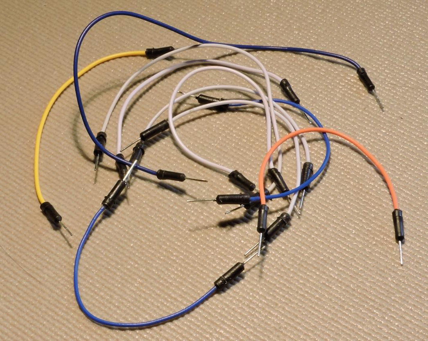
Figure 1-4 A random collection of DuPont wires
Male-to-male DuPont wires can be purchased in assorted sets on eBay for about the Buy-it-Now price of $2.00 US with free shipping. They might have auction titles like “65Pcs Male to Male Solderless Flexible Breadboard DuPont Jumper Cable Wires.” I recommend that you get the assorted sets so that you get different colors and lengths. A search like “DuPont wires male -female” should yield good results. The “-female” keyword will eliminate any ads that feature female connectors.
0.1 uF Bypass Capacitors
You might find that you can get by without bypass caps (capacitors), but they are recommended (shown in Figure 1-5 as yellow blobs on the power rails). These can be purchased in quantity from various sources, including eBay .
Try to buy quality capacitors like Metalized Polyester Film units if possible. The voltage rating can be as low as 16 volts. A few of these should be plugged into your supply rails on the breadboard, between the positive and negative rails, to filter out any voltage transients and noise.
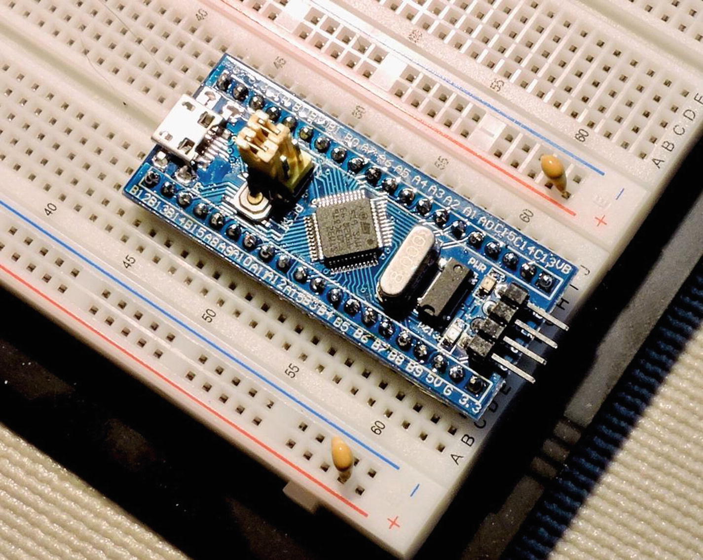
Figure 1-5 Breadboard with STM32F103C8T6 and 0.1 uF bypass capacitors installed on the rails
USB TTL Serial Adapter
This device is essential for some of the projects in this book. Figure 1-6 illustrates the unit that I used. This serial adapter is used to communicate data to your desktop/laptop. Without a display, this allows you to communicate through a virtual serial link (via USB) to a terminal program.
There are several types of these available on eBay and elsewhere, but be careful to get a unit with hardware flow control signals. The cheapest units will lack these additional signals (look for RTS and CTS). Without hardware flow control signals, you will not be able to communicate at high speeds, such as 115200 baud, without losing data.
If you’re running Windows, also be careful of buying FTDI (FTDI Chip) fakes. There were reports of FTDI software drivers bricking the fake devices at one time. Your choice doesn’t have to include FTDI, but if the device claims FTDI compatibility, be aware and check your driver support.
You’ll notice in Figure 1-6 that I have a tag tied to the end of the cable. That tag reminds me which colored wire is which so that I can hook it up correctly. You might want to do something similar.

Figure 1-6 A USB-to-TTL serial (5V) adapter cable
These are normally 5-volt devices and are hence TTL compatible. Note, however, that one of the features of the STM32F103 family of devices is that many of the GPIO pins are 5-volt tolerant, even though the MCU operates from a +3.3-volt supply. This permits the use of these TTL adapters without causing harm. More will be said about this later. Other units can be purchased that operate at the 3.3-volt level or that can switch between 5 and 3.3 volts.
Power Supply
Most of the projects presented will run just fine off of the USB or TTL adapter power output. But if your project draws more than the usual amount of current, then you may need a power adapter. Figure 1-7 illustrates a good adapter to fit the breadboard power rails. It can be purchased from eBay for about $1.00 US with free shipping. Mine was advertised as “MB102 Solderless Breadboard Power Supply Module, 3.3V 5V for Arduino PCB Board.” If your breadboard lacks power rails, you may need to shop for a different type of breadboard.

Figure 1-7 A small breadboard power supply and 7.5 VDC adapter
The MB102 is convenient because it can be jumpered to supply 3.3 or 5 volts. Additionally, it includes a power on/off button.
The other consideration is the wall adapter to supply the input power (this is not included). While the MB102 accepts up to 12 volts of input, I found that most 9 VDC wall adapters had an open circuit voltage near 13 volts or more. I feel that those are risky because if the cheap MB102 fails for any reason, the over-voltage might leak through and damage your MCU unit(s) as well.
Foraging through my junk box of “wall warts,” I eventually found an old Ericsson phone charger rated at 7.5 VDC at 600 mA. It measured an unloaded voltage of 7.940 volts. This is much closer to the 5 and 3.3 volt outputs that the MB102 will regulate to. If you have to purchase a power adapter, I recommend a similar unit.
Small Stuff
There are some small items that you may already have. Otherwise, you will need to get some LEDs and resistors for project use. Figure 1-8 shows a random set of LEDs and a SIP-9 resistor.

Figure 1-8 A random collection of 5 mm LEDs and one SIP-9 resistor at the bottom
Usually an LED is targeted for about 10 mA of current for normal brightness. Smaller LEDs only require maybe 2 to 5 mA. With a supply voltage near 3.3 volts, you’ll want a resistor of about 220 Ω to limit the current (220 ohms limits the current to a maximum of approximately 7 mA). So, get a few 220 Ω resistors (1/8th watt will be sufficient).>
Another part you may want to consider stocking is the SIP-9 resistor. Figure 1-9 illustrates the internal schematic for this part. If, for example, you want to drive eight LEDs, you would need eight current-limiting resistors. Individual resistors work but require extra wiring and take up breadboard space. The SIP-9 resistor, on the other hand, has one connection common to the eight resistors. The other eight connections are the other end of the internal resistors. Using this type of package, you can reduce the parts count and wiring required.
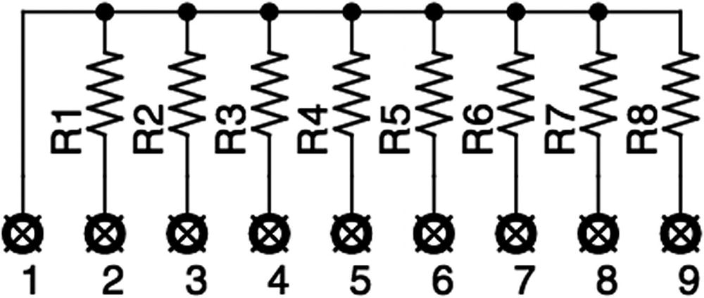
Figure 1-9 The internal schematic view of a SIP-9 resistor
Summary
This chapter has introduced the main actors that will appear in this book. It also itemized most of the things that you might need to acquire. The next chapter will guide you through the necessary steps of software installation. Once that is out of the way, the real fun can begin.