
One of the nice things about the STM32 MCU is the availability of the USB (Universal Serial Bus) peripheral. With USB, it is possible to communicate directly with a desktop platform in various modes. One of these flexible modes is USB’s emulation of a serial link between the MCU and the desktop.
This chapter will explore the use of libopencm3 and FreeRTOS working together to provide a convenient means of communication. You will use the USB CDC class of operation (USB communication device class). This provides a very convenient means for interacting with your Blue Pill.
Blue Pill USB Issue
First, let’s clear the air about the Blue Pill USB issue. What is this issue you may have read about in the Internet forums?
It turns out that the PCB is manufactured with a 10 kohm resistor (![]() ) pullup resistor to +3.3 volts, which is incorrect. For full-speed USB, this is supposed to be 1.5 kohm. You can test this by measuring resistance with your DMM between the A12 pin on the PCB and the +3.3-volt pin. You will likely read 10 kohms.
) pullup resistor to +3.3 volts, which is incorrect. For full-speed USB, this is supposed to be 1.5 kohm. You can test this by measuring resistance with your DMM between the A12 pin on the PCB and the +3.3-volt pin. You will likely read 10 kohms.
This defect does not always prevent it from working, however. For example, I had no difficulty using USB from the STM32 to a MacBook Pro. But your mileage may vary. The hard way to correct this is to replace ![]() on the PCB, but this is difficult because the resistor is so incredibly small.
on the PCB, but this is difficult because the resistor is so incredibly small.
Caution
Many people have reported in online forums that their Blue Pill USB connector has broken off or become inoperable. Exercise extra-gentle care when inserting the cable.
Correction of the issue is best accomplished by placing another resistor in parallel with it. Placing a 1.8 kohm resistor in parallel with the 10 kohm resistor produces a combined resistance of 1.5 kohms. Figure 7-1 illustrates how the author soldered a resistor to one of his units. The 1/8-Watt resistor is simply soldered carefully between pins A12 and the +3.3-volt pin. It’s not pretty, but it works!
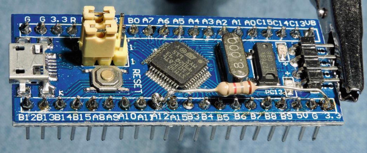
Figure 7-1 Correcting the USB pullup by addition of a 1.8-kohm resistor
To see how pullup resistance makes a difference, look at the scope trace in Figure 7-2. This is what the D+ line looked like with the default 10-kohm resistor.

Figure 7-2 D+ line scope trace using 10-kohm pullup resistance
In the figure, you can see a rise at the start followed by a slump to perhaps the 70 percent level. To the right where the high-frequency signals begin, you can see that the signal rests at about the 70 percent level in between excursions. Attach this device to a different PC USB port or hub and the degradation might be worse.
Compare this to Figure 7-3, which is a scope trace after the 1.5-kohm pullup resistance was in effect.
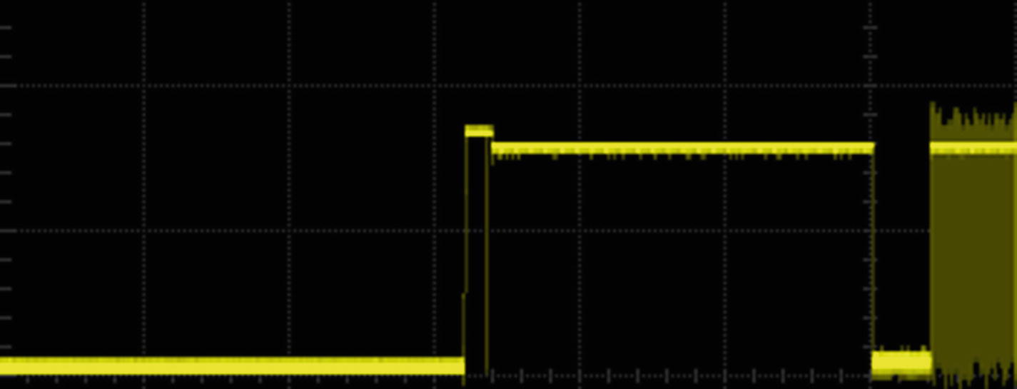
Figure 7-3 D+ line scope trace with 1.5-kohm pullup resistance
Ignoring capture-timing differences, you can see that the signal rests much higher, perhaps at the 90 percent level. This helps to assure improved signal thresholds.
Introduction to USB
USB is a popular means of communication from a personal computer to various peripherals, such as printers, scanners, keyboards, and a mouse. Part of its success is due to its standardization and low cost. The standard also includes USB hubs allowing the cost-effective extension of the network to accommodate additional devices.
In USB communication, the host directs all traffic. Each device is polled on a regular basis based upon its configuration and requirements. A keyboard infrequently needs to send data, for example, while a sound-recording device needs to send bulk recording data in real time. These differences are accommodated by the USB standard and are part of the device configuration.
Pipes and Endpoints
USB uses the concept of endpoints with connecting pipes to carry the data. The pipe carries the information, while the endpoints send or receive. Every USB device has at least one endpoint known as endpoint 0. This is a default and control endpoint, which allows host and device to configure device-specific operations and parameters. This occurs during device enumeration.
Figure 7-4 provides a high-level view of endpoints 0, 1, and 2 that we will be using in the example program. Technically, endpoint 0 is just one pipe. It is drawn here as two pipes because the control endpoint permits a response back to the host. All other endpoints have data travelling in one direction only. Note that the “In” and “Out” in Figure 7-4 are labeled according to the host controller’s viewpoint.

Figure 7-4 USB pipes and endpoints
A device may have additional endpoints, but our USB CDC example only needs two in addition to the required control endpoint 0:
Endpoint 1 is the device’s receiving endpoint (host’s sending, specified as 0x01)
Endpoint 2 is the device’s sending endpoint (host’s receiving, specified as 0x82)
As will be seen in the source code, bit 7 of the endpoint number indicates whether it is an input or output (with respect to the host controller). The value 0x82 indicates in hexadecimal that endpoint 2 (with bit 7) is sending (from the device’s point of view). Unlike a TCP/IP socket, USB pipes transfer data in one direction only.
As you may have realized, one potentially confusing aspect of USB programming is that input and output are specified in the code from the host controller’s point of view. For example, endpoint 0x82 is a receiving (input) endpoint from the host’s point of view. This tends to be confusing when writing for the device. Be aware of that when setting up USB descriptors.
This necessarily has been a brief introduction to USB. Entire books have been written on the subject, and the interested reader is encouraged to seek them out. Our focus will be limited to the successful use of the USB peripheral for the benefit of our STM32. Let’s get started!
USB Serial Device
With the MCU flashed and plugged into the system, you need to access it on your operating system as a serial device. This practice varies with the operating system, which complicates things slightly. The MCU source code is found in the following directory:
$ cd ~/stm32f103c8t6/rtos/usbcdcdemo
$ make clobber
$ make
$ make flash
The preceding steps will build and flash the code into your MCU device. The following sections will describe details on the desktop side of the USB conduit.
Linux USB Serial Device
Under Linux, with the STM32 flashed and plugged into a USB port, you can use the lsusb command to view the connected devices:
$ lsusb
Bus 002 Device 003: ID 0483:5740 STMicroelectronics STM32F407
In this example, I only had one device. Don’t be worried about the STM32F407 designation. This is just the description given to the device ID 0483:5740 that ST Microelectronics registered. But how do you find out what device path to use? Try the following after plugging in your cable:
$ dmesg | grep 'USB ACM device'
[  709.468447] cdc_acm 2-7:1.0: ttyACM0: USB ACM device
This is obviously not very user friendly, but from this you find that the device name is /dev/ttyACM0. Listing it confirms this:
$ ls -l /dev/ttyACM0
crw-rw---- 1 root dialout 166, 0 Jan 25 23:38 /dev/ttyACM0
The next problem is having permissions to use the device. Notice that the group for the device is dialout. Add yourself to the dialout group (substitute fred with your own user ID):
$ sudo usermod -a -G dialout fredLog out and log in again to verify that you have the correct group:
$ id
uid=1000(fred) gid=1000(fred) groups=1000(fred),20(dialout),24(cdrom),...
Being a member of the dialout group saves you from having to use root access to access the serial device.
MacOS USB Serial Device
Perhaps the simplest way to find the USB device under MacOS is to simply list the callout devices:
$ ls -l /dev/cu.*
crw-rw-rw- 1 root wheel 35,  1  6 Jan 15:14 /dev/cu.Bluetooth-Incoming-Port
crw-rw-rw- 1 root wheel 35,  3  6 Jan 15:14 /dev/cu.FredsiPhone-Wireless
crw-rw-rw- 1 root wheel 35, 45 26 Jan 00:01 /dev/cu.usbmodemFD12411
For the USB demo , the new device will appear as something like the path /dev/cu.usbmodemFD12411. The device number may vary, so look for cu.usbmodem in the pathname. Notice that all permissions are given.
Windows USB Serial Device
Serial devices under Windows show up as COM devices in the Device Manager once the cable is plugged in and the driver is installed. Figure 7-5 is an example screenshot.
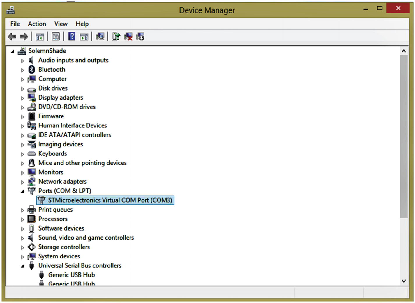
Figure 7-5 Example Windows Device Manager dialog
In this example, the USB device is attached as Windows port COM3. If you’re using Cygwin under Windows, the device pathname is /dev/ttyS2 (subtract 1 from the COM port number).
USB GPIO
The STMF103 series only supports USB on GPIO pins PA11 (USB_DM) and PA12 (USB_DP). There are no alternate configurations for USB. Further, there is no need to configure PA11 and PA12, because these are automatically taken over when the USB peripheral is enabled. 1 This is the only peripheral that I am aware of that behaves this way and is a tiny detail hidden in the reference manual RM0008 about alternate configurations. You do, however, need to enable the clocks for GPIOA and the USB peripheral.
Demo Source Code
Before running the supplied demo software, let’s examine some of the USB-related portions of code found in the directory (again):
$ cd ~/stm32f103c8t6/rtos/usbcdcdemoThe code that will be discussed is found in source module usbcdc.c. Listing 7-1 illustrates the initialization code for the USB peripheral, using the libopencm3 driver and FreeRTOS for data queues.
Listing 7-1 The usb_start() Function for Initializing USB
0386: void
0387: usb_start(void) {
0388:   usbd_device *udev = 0;
0389:
0390:   usb_txq = xQueueCreate(128,sizeof(char));
0391:   usb_rxq = xQueueCreate(128,sizeof(char));
0392:
0393:   rcc_periph_clock_enable(RCC_GPIOA);
0394:   rcc_periph_clock_enable(RCC_USB);
0395:
0396:   // PA11=USB_DM, PA12=USB_DP
0397:   udev = usbd_init(&st_usbfs_v1_usb_driver,&dev,&config,
0398:       usb_strings,3,
0399:       usbd_control_buffer,sizeof(usbd_control_buffer));
0400:
0401:   usbd_register_set_config_callback(udev,cdcacm_set_config);
0402:
0403:   xTaskCreate(usb_task,"USB",200,udev,configMAX_PRIORITIES-1,NULL);
0404: }
Lines 390 and 391 create FreeRTOS queues, which will be used to communicate to and from the USB stream, respectively.
Since enabling the USB peripheral automatically takes over the GPIOs PA11 and PA12, all we have to do is enable the GPIO and USB clocks in lines 393 and 394. After that is done, the libopencm3 routine usbd_init() performs the rest in lines 397 to 399.
Once the peripheral is initialized, the callback cdcacm_set_config() is registered in line 401. Finally, a FreeRTOS task is created in line 403 to service the USB events.
cdcacm_set_config()
When the USB peripheral is contacted by the host controller, it will call upon the callback illustrated in Listing 7-2 to configure/reconfigure the USB CDC device.
Listing 7-2 The cdcadm_set_config() Callback
0030: // True when USB configured:
0031: static volatile bool initialized = false;
...
0252: static void
0253: cdcacm_set_config(
0254:   usbd_device *usbd_dev,
0255:   uint16_t wValue __attribute__((unused))
0256: ) {
0257:
0258:   usbd_ep_setup(usbd_dev,
0259:       0x01,
0260:       USB_ENDPOINT_ATTR_BULK,
0261:       64,
0262:       cdcacm_data_rx_cb);
0263:   usbd_ep_setup(usbd_dev,
0264:       0x82,
0265:       USB_ENDPOINT_ATTR_BULK,
0266:       64,
0267:       NULL);
0268:   usbd_register_control_callback(
0269:       usbd_dev,
0270:       USB_REQ_TYPE_CLASS | USB_REQ_TYPE_INTERFACE,
0271:       USB_REQ_TYPE_TYPE | USB_REQ_TYPE_RECIPIENT,
0272:       cdcacm_control_request);
0273:
0274:   initialized = true;
0275: }
From lines 258 to 262, it can be seen that callback cdcacm_data_rx_cb() is registered so that it can receive data. From the host’s perspective, this is an OUT port, thus specified as endpoint 0x01 (OUT endpoint 1).
Next, lines 263 to 267 register another endpoint, which is considered as an IN port from the host controller’s perspective. Hence, the IN endpoint 2 is specified with the high bit on in the constant 0x82.
Finally, control requests will call upon callback cdcacm_control_request() as registered in lines 268 to 272.
Lastly, the Boolean variable initialized is set to true in line 274 so that other tasks can know the ready status of the USB infrastructure.
cdc_control_request()
The USB infrastructure uses the cdcacm_control_request() callback to act on specialized messages (Listing 7-3). This driver reacts to two req->bRequest message types, the first of which is to satisfy a Linux deficiency (lines 203 to 209).
Listing 7-3 The cdcacm_control_request() Callback
0190: static int
0191: cdcacm_control_request(
0192:   usbd_device *usbd_dev __attribute__((unused)),
0193:   struct usb_setup_data *req,
0194:   uint8_t **buf __attribute__((unused)),
0195:   uint16_t *len,
0196:   void (**complete)(
0197:     usbd_device *usbd_dev,
0198:     struct usb_setup_data *req
0199:   ) __attribute__((unused))
0200: ) {
0201:
0202:   switch (req->bRequest) {
0203:   case USB_CDC_REQ_SET_CONTROL_LINE_STATE:
0204:       /*
0205:        * The Linux cdc_acm driver requires this to be implemented
0206:        * even though it's optional in the CDC spec, and we don't
0207:        * advertise it in the ACM functional descriptor.
0208:        */
0209:       return 1;
0210:   case USB_CDC_REQ_SET_LINE_CODING:
0211:       if ( *len < sizeof(struct usb_cdc_line_coding) ) {
0212:           return 0;
0213:       }
0214:       return 1;
0215:   }
0216:   return 0;
0217: }
Lines 210 to 214 check on the length of a structure and return fail if the length is out of line (line 212). Otherwise, a return of 1 indicates a “handled” status (line 214).
cdcacm_data_rx_cb()
This callback is invoked by the USB infrastructure when data has been sent over the bus to the STM32 MCU. The first thing performed in line 228 is to determine how much buffer space is remaining assigned to variable rx_avail. If there is insufficient space available, the callback simply returns in line 233. The host will send the same data again, later.
If we have room for some data, we decide how much in line 236. The call to usbd_ep_read_packet() in line 239 then obtains some or all of the received data. Lines 241 to 244 send it to the receive queue for the receiving task. See Listing 7-4.
Listing 7-4 The USB Receive Callback
0222: static void
0223: cdcacm_data_rx_cb(
0224:   usbd_device *usbd_dev,
0225:   uint8_t ep __attribute__((unused))
0226: ) {
0227:   // How much queue capacity left?
0228:   unsigned rx_avail = uxQueueSpacesAvailable(usb_rxq);
0229:   char buf[64];    // rx buffer
0230:   int len, x;
0231:
0232:   if ( rx_avail <= 0 )
0233:       return;      // No space to rx
0234:
0235:   // Bytes to read
0236:   len = sizeof buf < rx_avail ? sizeof buf : rx_avail;
0237:
0238:   // Read what we can, leave the rest:
0239:   len = usbd_ep_read_packet(usbd_dev,0x01,buf,len);
0240:
0241:   for ( x=0; x<len; ++x ) {
0242:       // Send data to the rx queue
0243:       xQueueSend(usb_rxq,&buf[x],0);
0244:   }
0245: }
USB Task
The task that we created for the USB handling is a forever loop starting in line 284. The loop must call the libopencm3 driver routine usbd_poll() frequently enough that the USB link is maintained by the host. This is done at the top of the loop in line 285 of Listing 7-5.
Listing 7-5 The usb_task() Function
0278: static void
0279: usb_task(void *arg) {
0280:   usbd_device *udev = (usbd_device *)arg;
0281:   char txbuf[32];
0282:   unsigned txlen = 0;
0283:
0284:   for (;;) {
0285:       usbd_poll(udev); /* Allow driver to do its thing */
0286:       if ( initialized ) {
0287:           while ( txlen < sizeof txbuf
0288:              && xQueueReceive(usb_txq,&txbuf[txlen],0)
                           == pdPASS )
0289:               ++txlen; /* Read data to be sent */
0290:           if ( txlen > 0 ) {
0291:               if ( usbd_ep_write_packet(udev,0x82,
                                     txbuf,txlen) != 0 )
0292:                   txlen = 0; /* Reset if sent ok */
0293:           } else  {
0294:               taskYIELD(); /* Then give up CPU */
0295:           }
0296:       }
0297:   }
0298: }
The volatile bool variable initialized is checked in line 286. Until initialized is true, other USB calls like usbd_ep_write_packet() must be avoided.
After the driver has initialized, a check of the transmit queue is made in lines 287 to 289. As many queued characters as possible are taken from the queue to be sent. The sending of the USB data occurs in lines 290 to 292. If there are no characters to transmit, the FreeRTOS call to taskYIELD() is made to give another task CPU time.
From this, you can see that the purpose of this task is simply to send any queued bytes of data to the USB host. The receiving of data occurs from another place.
USB Receiving
When the application wants to read serial data, it calls upon usb_getc() or wrapper routines like usb_getline(). Listing 7-6 illustrates the code for usb_getc().
In line 367 you can see that it calls upon xQueueReceive() to pull a byte of received data from the queue. If there is no data, the call will block there because of the parameter given as portMAX_DELAY. Once the callback cdcacm_data_rx_cb() is invoked and queues up data, this code will receive data and unblock.
While it should never happen, the return of -1 in line 369 is taken if the queue has been destroyed or otherwise has become non-functional. Normally, the single character is returned by line 370.
Listing 7-6 The Listing of Function usb_getc()
0362: int
0363: usb_getc(void) {
0364:   char ch;
0365:   uint32_t rc;
0366:
0367:   rc = xQueueReceive(usb_rxq,&ch,portMAX_DELAY);
0368:   if ( rc != pdPASS )
0369:       return -1;
0370:   return ch;
0371: }
USB Sending
To send a byte of data to USB, it is put into the FreeRTOS usb_txq by function usb_putc(), as shown in Listing 7-7. Before it does that, however, a check is made in line 307 to make sure that the USB driver is ready. If it is not available yet, taskYIELD() is called in line 308 to share the CPU cycles.
Once the USB driver is known to be ready, the byte is queued in line 312, where it will block if the queue is full. Once bytes are drained from that queue, the character is queued and the call returns.
Listing 7-7 Sending Data Through USB Using Function usb_putc()
0303: void
0304: usb_putc(char ch) {
0305:   static const char cr = '
';
0306:
0307:   while ( !usb_ready() )
0308:       taskYIELD();
0309:
0310:   if ( ch == '
' )
0311:       xQueueSend(usb_txq,&cr,portMAX_DELAY);
0312:   xQueueSend(usb_txq,&ch,portMAX_DELAY);
0313: }
...
0407: bool
0408: usb_ready(void) {
0409:   return initialized;
0410: }
To make things character friendly, the function usb_putc() checks to see if you are sending a (newline, also known as linefeed) character. If so, line 311 first sends a carriage-return character. Under Unix/Linux, this type of processing is known as cooked mode. The receiving side in the terminal emulator will then move the cursor to the start of the line before advancing to the next line because of the newline.
USB Serial Demo
To demonstrate serial I/O over USB, I’ve modified an open source text-based game written by Jeff Tranter. His source code, found in the module adventure.c, has been modified to use the USB routines that have just been covered.
To build the code to be flashed, perform the following:
$ make clobber
$ make
$ make flash
After flashing the MCU, gently push the USB cable into the STM32 and connect the other end of the cable to your laptop/PC. Assuming you know the device name (from earlier in the chapter), set up your minicom or other terminal program (review minicom instructions in Chapter 6 if necessary). I recommend you save these settings to a profile name like “usb2” since they differ from the USB settings used later in this book.
With everything ready, start your terminal emulator as follows:
$ minicom usb2Welcome to minicom 2.7OPTIONS:Compiled on Sep 17 2016, 05:53:15.Port /dev/cu.usbmodemFD12411, 16:56:26Press Meta-Z for help on special keys...Abandoned Farmhouse AdventureBy Jeff TranterYour three-year-old grandson has gonemissing and was last seen headed in thedirection of the abandoned family farm.It's a dangerous place to play. Youhave to find him before he gets hurt,and it will be getting dark soon...?
Don’t worry if you missed the introductory text in the session shown (you can obviously read it here or shut down minicom and start over). This can happen if you had to mess around with the configuration of minicom. Entering “help” will get you the important information you need.
From the first screen, you can read about the adventure. Information is available by typing “help”:
? help
Valid commands:
go east/west/north/south/up/down
look
use <object>
examine <object>
take <object>
drop <object>
inventory
help
You can abbreviate commands and
directions to the first letter.
Type just the first letter of
a direction to move.
?
The game consists of using a verb and sometimes an object. The following session gives you a sample:
? look
You are in the driveway near your car.
You see:
  key
You can go: north
? take key
Took key.
? inventory
You are carrying:
  flashlight
  key
?
Summary
USB is a large subject because it must adapt to many different uses. The serial stream shown in this chapter is one of the many applications of USB. Additionally, control structures were declared but left undescribed from the source module usbcdc.c. The interested reader is encouraged to study them and experiment with the source code. Several books have been written about USB, and this project gives you a foundation from which to start.
You have also seen how a convenient USB interface can be constructed between the STM32 and your laptop/PC. No baud rates, data bits, stop bits, parity, or flow control were required for you to configure the USB. Provided that the necessary driver support is present on the USB host, it is as simple as plugging in your cable.
While the focus has been on USB as a serial communications medium, the demo also highlighted some FreeRTOS facilities, like tasks and message queues. Having separately executing tasks and safe inter-task communications greatly simplifies application development.
Finally, the known USB defect of the Blue Pill is actually not that difficult to correct. Given the power of the STM32 MCU, available at the price of an AVR device, there is no reason for anyone to miss out on the fun!
Bibliography
Reference Manual RM0008, http://www.st.com/resource/en/reference_manual/cd00171190.pdf , Table 29, page 167.