
The OLED (organic light-emitting diode) provides the hobbyist with an exciting form of low-cost display. Because they are based upon LEDs, they require no backlighting like an LCD device does, nor polarizing filters. This equates to lower cost.
The OLED device used in this chapter is monochrome, though it may display two colors in addition to black. That sounds contradictory, but the monochrome nature just means that it only displays one color for a given pixel. OLEDs with dual colors will have a band of pixels in one color, with the remainder in another. The background is always black (LED not lit).
The devices available today are small, usually 128 x 32 or 128 x 64 pixels in size. The physical dimensions also tend to be small. Yet because of their low cost and vivid color, they make great display widgets. This chapter will demonstrate the display of an analog meter on an OLED.
OLED Display
The unit I purchased from eBay was advertised as “White/Blue/Yellow Blue 0.96” SPI Serial 128 x 64 OLED LCD LED Display Module S” for a few dollars. But be wary of the “I2C” versus “SPI” in the listing. Many vendors don’t get this right.
The important thing is that the OLED should use the SSD1306 controller for the demo software. The display itself is WiseChip part number UG-2864HSWEG01, although the auction might not state that. Some eBay offers may be selling display part number UG-2864AMBAG01, which is considerably different and can’t be used with this chapter’s software. If you don’t mind paying a little more, Adafruit sells them as “Monochrome 0.96” 128 x 64 OLED graphic display.” Buying from them is easier than trying to obtain the correct part from eBay.
Figure 12-1 illustrates the OLED display I am using. The Adafruit OLED is similar, but the backside of the PCB differs. This chapter’s software requires a unit 128 pixels wide by 64 pixels high.

Figure 12-1 The OLED using a SSD1306 controller
Configuration
For this demo, you want a unit configured for four-wire SPI. The bottom side configures the device according to the resistors installed (Figure 12-2). Note that R3 and R4 are installed in the figure, confirming that this unit is configured for four-wire SPI. Those using the Adafruit unit should have jumper pads SJ1 and SJ2 unconnected.
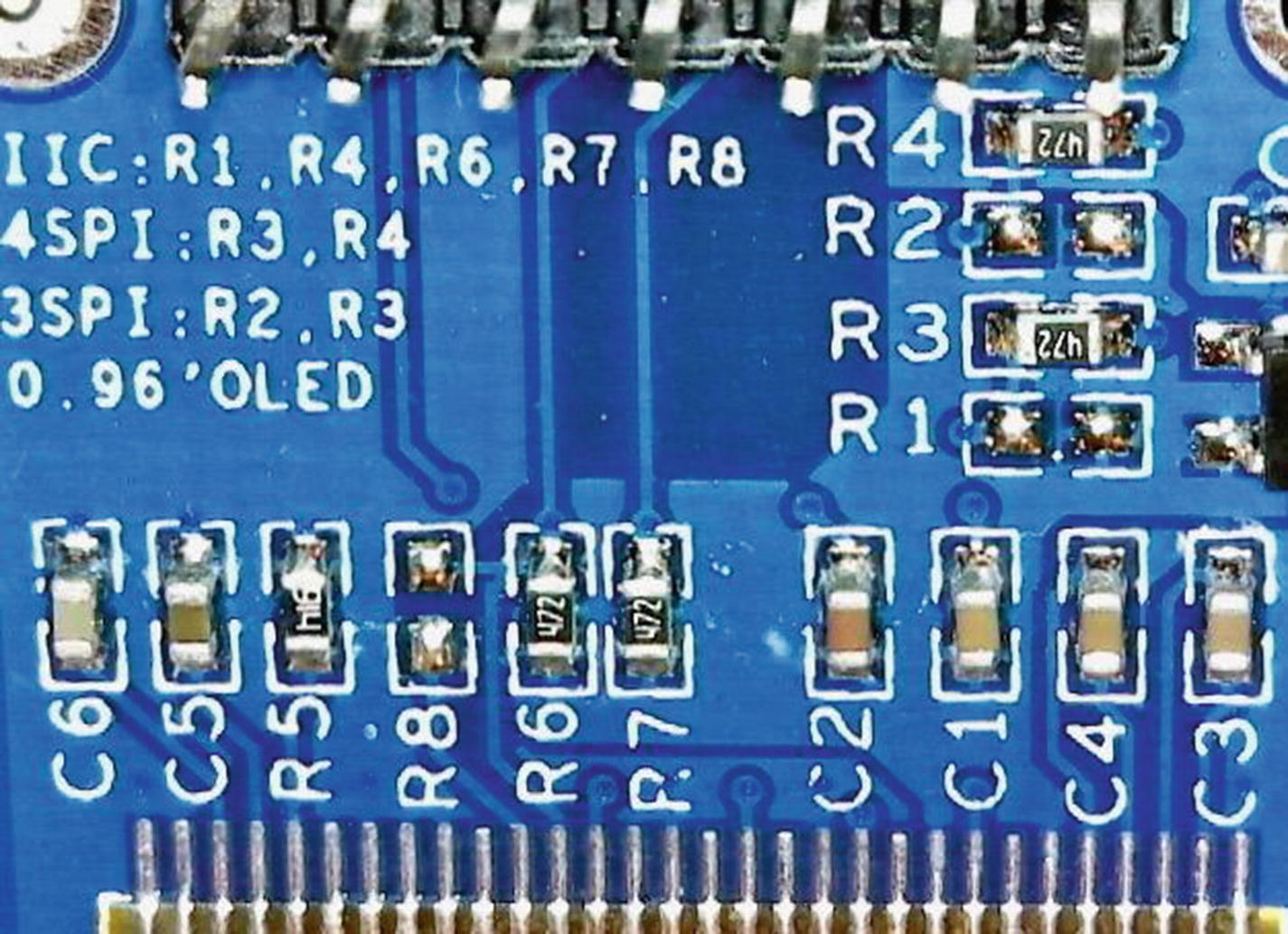
Figure 12-2 The backside of the OLED, illustrating the configuration resistors R1 through R8
Table 12-1 summarizes the different configurations possible. The four-wire SPI reference refers to the normal three SPI signals plus an additional line indicating a command or data signal. This extra line goes low to indicate when a command byte is being sent, and high for display data.
Table 12-1 OLED Configurations
R1 | R2 | R3 | R4 | Configuration |
|---|---|---|---|---|
In | Out | Out | In | I2C (not used for this demo) |
Out | Out | In | In | Four-wire SPI |
Out | In | In | Out | Three-wire SPI (not used for this demo) |
Display Connections
The display unit comes with seven connections, listed in Table 12-2. The ![]() connection is optional and should be wired high (inactive) if unused. The demo program will use a GPIO to activate reset at startup.
connection is optional and should be wired high (inactive) if unused. The demo program will use a GPIO to activate reset at startup.
The precise current draw will depend upon several factors. Adafruit suggests that typical current may be about 20 mA. In my own testing, I measured a current of 13.2 mA with all pixels on. But different OLED configuration options may increase current consumption. This level is low enough that it is safe to supply the OLED from the +3.3-volt regulator.
Table 12-2 OLED Connections
OLED Pin | Function | Description |
|---|---|---|
Gnd | Ground | Common return path |
VCC | 3.3 to 5.0 volts | Supply voltage (up to 20 mA) |
D0 (or SCK) | SCK | SPI system clock |
D1 (or SDA) | SDIN | SPI MOSI (system data in for OLED) |
RES | Reset | Reset signal (active low) |
DC | Data / Command | Data (high), Command (low) |
CS | ChipSelect | Chip select (active low) |
Display Features
Before examining the demo program, it is helpful to look at the OLED display features that it will be driving. Figure 12-3 illustrates the author’s OLED with all pixels turned on (using controller command 0xA5).

Figure 12-3 Author’s yellow/blue OLED with all pixels on
While this is a yellow/blue OLED, the display is monochrome. You only get yellow in the top sixteen rows. After a gap of one row, there are forty-eight rows of blue pixels below. Some single-color units might lack this gap. Choose carefully for your application.
With all pixels turned on, my OLED measured 13.3 mA of current.
Demo Schematic
The demo circuit uses the same SPI hookup we used in the Winbond project (Chapter 8) but uses a few extra control lines for the OLED device. This demo still uses SPI1 for the SPI controller but is using an alternate GPIO configuration, to be described later. PA15 is acting as ![]() that will drive the chip select of the OLED. PB10 will signal to the OLED whether commands or data are being sent. Finally, PB11 can be activated at startup to initialize the OLED when the demo program begins. Figure 12-4 illustrates the demo circuit.
that will drive the chip select of the OLED. PB10 will signal to the OLED whether commands or data are being sent. Finally, PB11 can be activated at startup to initialize the OLED when the demo program begins. Figure 12-4 illustrates the demo circuit.
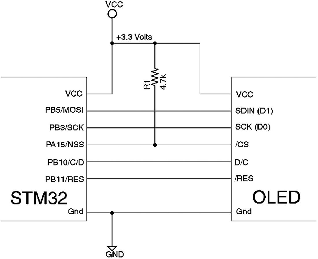
Figure 12-4 Demo OLED circuit using SPI
The ![]() pin of the OLED, which is wired to the SSD1306 controller, must remain low for a minimum of 3 μs for it to be effective. The reset sets the controller into several default modes, which saves some initialization.
pin of the OLED, which is wired to the SSD1306 controller, must remain low for a minimum of 3 μs for it to be effective. The reset sets the controller into several default modes, which saves some initialization.
AFIO
The STM32 platform supports the concept of remapping I/O functions. It is referred to in their documentation as “Alternate Function I/O.” This chapter’s demo takes advantage of this feature to have SPI1 appear on GPIOs PA15, PB3, PB4, and PB5. Table 12-3 lists the AFIO options for SPI1.
Table 12-3 Alternate Function I/O for SPI1
Alternate Function | SPI1_REMAP=0 | SPI1_REMAP=1 |
|---|---|---|
SPI1_NSS | PA4 | PA15 |
SPI1_SCK | PA5 | PB3 |
SPI1_MISO | PA6 | PB4 |
SPI1_MOSI | PA7 | PB5 |
The AFIO feature allows additional flexibility in planning your STM32 resources. If you needed 5-volt-tolerant inputs, you would want to use SPI1_REMAP=1. Sometimes AFIO is used to avoid conflict with pins used by another peripheral.
To take advantage of AFIO, you need to get the following ducks in a row:
Enable the AFIO clock.
Configure the alternate function.
Configure GPIO outputs for ALTFN. Inputs do not require special treatment other than to be configured as an input.
All three of these steps are essential. Forgetting to enable the AFIO clock, for example, will result in nothing happening or the peripheral hanging. Using libopencm3, the AFIO clock is enabled with the following:
rcc_periph_clock_enable(RCC_AFIO);The demo program uses the following libopencm3 call to choose SPI1’s alternate function using libopencm3’s gpio_primary_remap() function:
    // Put SPI1 on PB5/PB4/PB3/PA15
    gpio_primary_remap(
        AFIO_MAPR_SWJ_CFG_JTAG_OFF_SW_OFF, // Optional
        AFIO_MAPR_SPI1_REMAP);             // SPI1_REMAP=1
The first argument disables JTAG functionality and is secondary to our goal of remapping. The second argument indicates that you want SPI1 to be remapped (SPI_REMAP=1 in Table 12-3). The natural mapping (SPI1_REMAP=0) is used by default after a system reset.
For GPIO outputs, you must choose one of the following macros when configuring it. Otherwise, the peripheral would not be able to reach the output pins.
GPIO_CNF_OUTPUT_ALTFN_PUSHPULL
GPIO_CNF_OUTPUT_ALTFN_OPENDRAIN
For example:
    gpio_set_mode(
        GPIOB,
        GPIO_MODE_OUTPUT_50_MHZ,
        GPIO_CNF_OUTPUT_ALTFN_PUSHPULL,  // Note!
        GPIO5|GPIO3);
Notice the ALTFN in the argument three macro name. An easy mistake to make is to use the non-ALTFN macro instead and then wonder why your peripheral is not communicating with the pin.
Graphics
One of the hurdles when working with graphics devices is performing operations like drawing lines, circles, and rectangles. It is true that lines and rectangles are simple enough if they use perfectly horizontal and vertical lines. But lines tilted on an angle and filled circles present a challenge. Then, there is the need for fonts.
These software problems are large enough that the average developer doesn’t want to expend time on re-developing solutions for them. After all, these are problems that have been solved before. Why do we have to keep solving them again?
The good news is that the problem has been solved before and that the software is available in open source form. The demo project in this chapter will employ the graphics software written by Achim Döbler, available on github here:
https://github.com/achimdoebler/UGUIThe one characteristic of this graphics software that I give the author kudos for is that it is designed to be adapted to any graphics platform. Aside from some simple configuration in the ugui_config.h file, the only other requirement is a user-supplied function:
void
local_draw_point(UG_S16 x,UG_S16 y,UG_COLOR c) {
        ...
}
Given x and y coordinates and a color, this function is called upon to draw a point in your own graphics environment. To make this work, the uGUI environment is simply initialized with a function pointer:
static UG_GUI gui;
    ...
    UG_Init(&gui,local_draw_point,128,64);
The arguments 128 and 64 in this example define the maximum width and height of the drawing canvas. Once this has been done, uGUI functions can be called upon to fill a circle; for example:
UG_FillCircle(x,y,c);The demo project is located in the following directory:
$ cd ~/stm32f103c8t6/rtos/oledOur OLED device, however, is monochrome, so some special color handling is needed. To translate color into monochrome, the following routine is provided in meter.c:
0059: static int
0060: ug_to_pen(UG_COLOR c) {
0061:
0062:   switch ( c ) {
0063:   case C_BLACK:
0064:       return 0;
0065:   case C_RED:
0066:       return 2;
0067:   default:
0068:       return 1;
0069:   }
0070: }
This function merely converts any color except for red and white to a 1 (white), with black represented as a 0. The color red is used by the demo software to represent exclusive-or.
The exclusive-or operation has the special property that if the pixel is currently 0 (black) it will be painted as white. If the current pixel is white, then it is converted to black. Regardless of the current state of the graphics canvas, something is always visibly drawn in exclusive-or mode.
Tip
Depending upon your compiler and options used, you may want to spend time reducing the amount of code compiled. Use #if to eliminate unused functions in the ugui.c module.
The Pixmap
To facilitate graphic drawing on the OLED, a pixel map (pixmap) buffer is used. This allows extensive drawing operations to occur at full CPU speed. At the appropriate time, the pixmap is then copied to the OLED device for display.
The pixmap is defined in the file meter.c as follows:
static uint8_t pixmap[128*64/8];This defines 128 times 64 pixels, with eight pixels to a byte, thus using 1024 bytes of SRAM.
To facilitate drawing into the pixmap, the to_pixel() function is used, illustrated in Listing 12-1. It computes a byte address within the pixmap based upon the given x and y coordinates and then returns a bit number through the pointer argument bitno.
Listing 12-1 The to_pixel() Function
0020: static uint8_t dummy;
0021:
0022: static uint8_t *
0023: to_pixel(short x,short y,unsigned *bitno) {
0024:   *bitno = 7 - y % 8;      // Inverted
0025:
0026:   if ( x < 0 || x >= 128
0027:     || y < 0 || y >= 64 )
0028:         return &dummy;
0029:
0030:   unsigned inv_y = 63 - y;
0031:   unsigned pageno = inv_y / 8;
0032:   unsigned colno = x % 128;
0033:
0034:   return &pixmap[pageno * 128 + colno];
0035: }
A couple of points require explaining. Lines 24 and 30 are used to invert the display. This was done to arrange that the yellow band of 16 rows would appear as the top of the display. To use non-inverted coordinates, you would change line 24 from:
0024: *bitno = 7 - y % 8; // Invertedto
0024: *bitno = y % 8; // Non-invertedLikewise, y would be used instead of the computed inv_y value. Centralizing this mapping in one place makes it possible to introduce translations to the display. For example, you could rework this function to transform x and y to display on the device in portrait mode rather than landscape.
In theory, there should be no call to this routine with the x and y coordinates out of range. But should that happen, the routine returns a pointer to the value dummy so that the call can be ignored without fatal consequences.
Pixmap Writing
After the byte and bit numbers have been determined by the to_pixel() function, the actual point-drawing function becomes simpler, shown in Listing 12-2. The draw_point() function is called by the earlier local_draw_point() function. The draw_point() routine expects the 2, 1, or 0 pen value rather than a color.
Listing 12-2 The Internal draw_point() Function
0037: static void
0038: draw_point(short x,short y,short pen) {
0039:
0040:   if ( x < 0 || x >= 128 || y < 0 || y >= 64 )
0041:       return;
0042:
0043:   unsigned bitno;
0044:   uint8_t *byte = to_pixel(x,y,&bitno);
0045:   uint8_t mask = 1 << bitno;
0046:
0047:   switch ( pen ) {
0048:   case 0:
0049:       *byte &= ~mask;
0050:       break;
0051:   case 1:
0052:       *byte |= mask;
0053:       break;
0054:   default:
0055:       *byte ^= mask;
0056:   }
0057: }
Lines 40 and 41 exit the function without doing anything when the x and/or y coordinates are out of range. Otherwise, lines 43 and 44 determine the byte address and bit number for the pixel being altered. Line 45 computes a bit mask from the bitno value and saves it to mask.
What happens next depends upon the pen value. If the pen was 0 (white), that bit is masked out so that the pixel bit is cleared to zero. If the pixel is 1, the mask value is or-ed with the byte to produce a 1-bit in the pixel. Finally, in line 55, the default pen value (2 normally) will produce an exclusive-or of the pixel instead.
The Meter Software
The graphics software specific to the meter display is found in the file meter.c. Those interested in the design of this program can examine the source code for the details. For brevity, I’ll just highlight the important functions within it.
meter_init()
void meter_init(struct Meter *m,float range);If this were C++, you could think of the meter_init() function as the constructor. The struct Meter m is initialized by the call, while the float argument range configures the meter’s upper range. In the demo main.c program, range is provided as 3.5 for 3.5 volts.
meter_set_value()
void meter_set_value(struct Meter *m,float v);This function changes the value stored in meter object m to the value v. This will move the graphics pointer in the pixmap.
meter_redraw()
void meter_redraw(struct Meter *m);This function is used internally at initialization time to draw the entire meter into the pixmap. It can be called again if the software suspects or knows that the image was corrupted somehow. In the demo, this is only called once at initialization.
meter_update()
This is the function used to transfer the pixmap in SRAM to the OLED using SPI1:
void meter_update(void);The SPI transfer code is illustrated in Listing 12-3.
Listing 12-3 The meter_update() SPI Transfer Function
0195: void
0196: meter_update(void) {
0197:   uint8_t *pp = pixmap;
0198:
0199:   oled_command2(0x20,0x02);// Page mode
0200:   oled_command(0x40);
0201:   oled_command2(0xD3,0x00);
0202:   for ( uint8_t px=0; px<8; ++px ) {
0203:       oled_command(0xB0|px);
0204:       oled_command(0x00); // Lo col
0205:       oled_command(0x10); // Hi col
0206:       for ( unsigned bx=0; bx<128; ++bx )
0207:           oled_data(*pp++);
0208:   }
0209: }
Line 197 obtains the address of the first byte of the pixmap. Line 199 makes certain that the SSD1306 controller is in “page mode.” In this mode, the OLED memory is broken up into eight pages of 128 bytes of pixels.
Line 200 initializes the SSD1306 to start at display line zero, while line 201 initializes the SSD1306 to set the display offset to zero.
The loop in lines 202 to 208 then takes care of transferring data one page at a time to the OLED. Line 203 chooses the OLED page to update. Lines 204 and 205 initialize the column index to zero. Lines 206 and 207 actually pass the data to the OLED controller and update the display pixel data pointer pp.
The functions oled_command(), oled_command2(), and oled_data() are found in the demo module main.c.
Main Module
Since the OLED module requires some special processing with the Data/Command signal line, let’s examine the functions used by the meter program.
oled_command()
This function is used to send command bytes to the OLED controller and is illustrated in Listing 12-4.
Listing 12-4 The oled_command() Function
0034: void
0035: oled_command(uint8_t byte) {
0036:   gpio_clear(GPIOB,GPIO10);
0037:   spi_enable(SPI1);
0038:   spi_xfer(SPI1,byte);
0039:   spi_disable(SPI1);
0040: }
Line 36 clears GPIO PB10 so that the Data/Command line goes low, indicating to the OLED controller that SPI data is to be interpreted as command bytes. Lines 37 to 39 transfer this command byte over SPI1.
oled_command2() is identical, except that it sends two command bytes instead of one.
oled_data()
The oled_data() function is very similar to oled_command(). It simply sets the GPIO line PB10 high (line 53 of Listing 12-5) so that the OLED controller will accept SPI data as pixel data.
Listing 12-5 The oled_data() Function
0051: void
0052: oled_data(uint8_t byte) {
0053:   gpio_set(GPIOB,GPIO10);
0054:   spi_enable(SPI1);
0055:   spi_xfer(SPI1,byte);
0056:   spi_disable(SPI1);
0057: }
oled_reset()
The main module calls upon function oled_reset() to initialize the OLED controller, as shown in Listing 12-6.
Listing 12-6 The oled_reset() Function
0059: static void
0060: oled_reset(void) {
0061:   gpio_clear(GPIOB,GPIO11);
0062:   vTaskDelay(1);
0063:   gpio_set(GPIOB,GPIO11);
0064: }
Line 61 sets PB11 to low. Then, FreeRTOS routine vTaskDelay() is called for one tick (about 1 ms), which should be more than enough time (a minimum of 3 μs is required). Then, after the delay in line 62, the PB11 pin is brought high again.
oled_init()
The function oled_init is illustrated in Listing 12-7. Lines 73 and 77 are non-essential, simply activating the built-in LED on PC13. The OLED is reset in line 74 and is followed by several commands sent to it from the array cmds (line 68) from the loop in lines 75 and 76.
Listing 12-7 The oled_init() Function
0066: static void
0067: oled_init(void) {
0068:   static uint8_t cmds[] = {
0069:       0xAE, 0x00, 0x10, 0x40, 0x81, 0xCF, 0xA1, 0xA6,
0070:       0xA8, 0x3F, 0xD3, 0x00, 0xD5, 0x80, 0xD9, 0xF1,
0071:       0xDA, 0x12, 0xDB, 0x40, 0x8D, 0x14, 0xAF, 0xFF };
0072:
0073:   gpio_clear(GPIOC,GPIO13);
0074:   oled_reset();
0075:   for ( unsigned ux=0; cmds[ux] != 0xFF; ++ux )
0076:       oled_command(cmds[ux]);
0077:   gpio_set(GPIOC,GPIO13);
0078: }
Demonstration
In the project directory, perform the following:
$ make clobber
$ make
$ make flash
Once your STM32 is flashed and wired up according to the schematic in Figure 12-4, you should be able to unplug the programmer and then plug in the USB cable for the STM32 device. After a brief pause, you should see the display in Figure 12-5, if everything is working. Depending upon your device, you may see different colors.
Tip
When developing a new project, if the linker tells you that .bss will not fit in region ram, review the value of configTOTAL_HEAP_SIZE in file FreeRTOSConfig.h. You may need to reduce the heap size to make room for your program’s own storage.
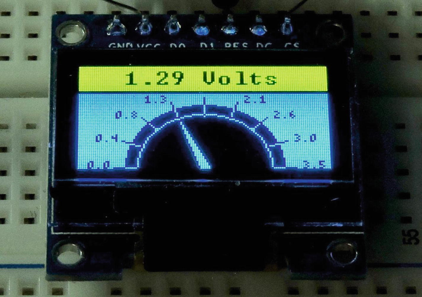
Figure 12-5 The demonstration program produces a voltmeter graphic on the OLED
If the display did not initialize correctly, it is best to immediately unplug the USB cable and recheck your wiring. If successful, start up minicom with your USB startup settings (mine is named “usb”):
$ minicom usbAfter minicom connects to your USB device and starts, you should see a session display like the following:
Welcome to minicom 2.7OPTIONS:Compiled on Sep 17 2016, 05:53:15.Port /dev/cu.usbmodemWGDEM1, 22:46:21Press Meta-Z for help on special keys
Press the Return key to prompt a menu display from the demo program:
Test Menu:0 .. set to 0.0 volts1 .. set to 1.0 volts2 .. set to 2.0 volts3 .. set to 3.0 volts4 .. set to 3.5 volts+ .. increase by 0.1 volts- .. decrease by 0.1 volts: _
Pressing “1” should immediately cause the meter (OLED) to display 1.0 volts. Likewise, pressing “3” points the meter at 3 volts. Pressing the “+” or “-” key will allow you to increase/decrease respectively the voltage displayed by tenths of a volt.
Summary
In this chapter, SPI was applied to the real-world problem of driving an OLED display. In doing so, the advantage of using open-sourced software for graphics operations was demonstrated. Graphics permitted the drawing of an analog meter on the OLED as well as the use of a font to display the voltage digitally.
Moreover, the signals for Data/ ![]() and
and ![]() were demonstrated to drive the OLED display, in addition to the usual SPI signals.
were demonstrated to drive the OLED display, in addition to the usual SPI signals.
The concept of AFIO for the STM32 family was also applied in this chapter to demonstrate how SPI1 could have its I/O pins moved to different pins. AFIO permits greater flexibility in applying the resources of the STM32 chip.