A well-designed data model is the cornerstone to building business intelligence (BI) and data warehousing (DW) applications that provide significant business value. Effective data modeling results in transforming data into an enterprise information asset that is consistent, comprehensive, and current. Data is transformed from operational or source systems into a data warehouse, data marts, or online analytical processing (OLAP) cubes for analysis. Entity-relationship (ER) modeling (also referred to in the industry as relational modeling) is one of two logical data modeling approaches. There are three levels of data models: conceptual, logical, and physical. The modeling workflow includes gathering business requirements, creating the models, and supporting application development. An ER model is made up of entities, relationships, and attributes. The ER model is used for transactional systems primarily because it minimizes data redundancy and ensures data integrity. The approach to reduce redundancy is called normalization, which is a formal data modeling approach to examining and validating a model and putting it into a particular normalized form. The ER model is often called a third normal form (3NF) or a normalized model.
Keywords
3NF; Attribute; Conceptual data model; Entity; Entity-relationship modeling; ER modeling; Logical data model; Normalized model; Physical data model; Relationship; Third normal form
Information in This Chapter:
• Introduction to data modeling
• Three levels of data models: conceptual, logical and physical
A well-designed data model is the cornerstone to building business intelligence (BI) and data warehousing (DW) applications that provide significant business value. Effective data modeling results in transforming data into an enterprise information asset that is consistent, comprehensive, and current. Data is transformed from operational or source systems into a data warehouse, data marts, or online analytical processing (OLAP) cubes for analysis.
This chapter discusses the first of two logical data modeling approaches: entity-relationship (ER) modeling, also referred to in the industry as relational modeling. (The next chapter will cover the other approach, dimensional modeling.) ER modeling is used to establish the baseline, operational data model, while dimensional modeling is the cornerstone to BI and DW applications. These modeling techniques have expanded and matured as best practices have emerged from years of experience in data modeling in enterprises of all sizes and industries. These techniques improve the business value of the data, enhance project productivity, and reduce the time to develop applications.
Definitions—The Difference Between a Data Model and Data Modeling
Before reading any further, it is a good idea to learn how we define a data model and data modeling.
A data model is a specification of the data structures and business rules representing business requirements. One of the first things you do when developing an application is talk to the business group about their requirements, then document them. In addition to those requirements, there will be a set of data that is required to run that application, whether it is a reporting, analysis, or transaction processing system. In addition to this necessary data, there will be business rules that define the relationship between the various data entities or objects that are required. The data model represents the data portion of those rules and the relationships between those structures.
The data model’s primary job is to be the data design specification for an IT application. The team meets and develops the reporting or application specifications for the code. But that code needs to operate on data. And the data model is the data design specification for that portion of the application.
Data modeling is a structured approach to identify and analyze those data components of the information system specifications. This approach involves close work between the business and IT groups and adherence to a best practices approach to ensure that the data model is most appropriate for building the application.
The data model provides a method to visually communicate the data that is needed, collected, and used by an organization. Data modeling tools present visual representations of data models. As your data model gets used in dozens or even thousands of tables, the visual representation is very important as it shows the relationships between the tables—relationships that would not show up if it was just text.
As a communication tool, the data model is best used for discussions between developers, database analysts, and business analysts during design and application development. Although there are some business people with whom the models can be shared, it can be too complex for most and should be limited to the technical members of the team. The conceptual data model, described below, is an exception to this.
Three Levels of Data Models
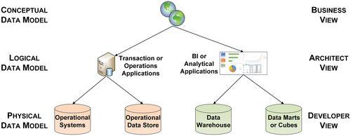
There are three levels of data models, which grow increasingly complex: conceptual, logical. and physical. Figure 8.1 shows how they relate to one another.
The conceptual data model represents the high-level business view. This is very effective for communicating with the business to understand and define the business processes within the enterprise.
FIGURE 8.1Three levels of data models.
The logical data model is the next layer down, and is the one we are most involved in when designing the BI application. It helps us understand the details of the data, but not how it is implemented. The logical data model is the architect or designer view of the data. This chapter covers two use cases:
1. Transactional or operation applications such as enterprise resource planning (ERP) systems.
2. BI or analytical applications such as DW, data marts, and OLAP cubes.
The physical data model makes up the third tier. The logical data model is used as the blueprint of what data is involved while the physical data models detail how that data will be implemented. Then database administrators and application developers will convert the logical data model into the tables, columns, keys, and other physical entities of a database. The database design for operational and transactional systems is derived from ER logical data models while BI-related databases use logical dimensional models. Application developers use the physical data model to design, build, and test application systems.
Conceptual Data Model
The conceptual data model is a structured business view of the data required to support business processes, record business events, and track related performance measures. This model focuses on identifying the data used in the business but not its processing flow or physical characteristics. This model’s perspective is independent of any underlying business applications. For example, it allows business people to view sales data, expense data, customers, and products—business subjects that are in the integrated model and outside of the applications themselves.
The conceptual data model represents the overall structure of data required to support the business requirements independent of any software or data storage structure. The characteristics of the conceptual data model include:
• An overall view of the structure of the data in a business context.
• Features that are independent of any database or physical storage structure.
• Objects that may not ever be implemented in physical databases. There are some concepts and processes that will not find their way into models, but they are needed for the business to understand and explain what is needed in the enterprise.
• Data needed to perform business processes or enterprise operations.
The conceptual data model is a tool for business and IT to define:
• Data requirements scope.
• Business terms and measures across different business units and those that are agreed upon for enterprise-wide usage.
• Names, data types, and characteristics of entities and their attributes.
Logical Data Model
The logical data model is the one used most in designing BI applications. It builds upon the requirements provided by the business group. It includes a further level of detail, supporting both the business system-related and data requirements.
The business rules are appropriated into the logical data model, where they form relationships between the various data objects and entities. As opposed to a conceptual data model, which may have very general terms, the logical data model is the first step in designing and building out the architecture of the applications.
Like the conceptual data model, the logical data model is independent of specific database and data storage structures. It uses indexes and foreign keys to represent data relationships, but these are defined in a generic database context independent of any specific DBMS product.
The characteristics of the logical data model include:
• Features independent of specific database and data storage structures.
• Specific entities and attributes to be implemented.
• Identification of the business rules and relationships between those entities and attributes.
• Definitions of the primary keys, foreign keys, alternate keys, and inversion entities.
The logical model is used as a bridge from the application designer’s view to the database design and the developer’s specifications. This model should be used to validate whether the resulting applications that are built fulfill business and data requirements.
Physical Data Model
Implementing the physical data model requires understanding the characteristics and performance constraints of the database system being used. Quite often, it is a relational database, and you will have to understand how the tables, columns, data types, and the relationships between tables and columns are implemented in the specific relational database product. Even if it is another type of database (multidimensional, columnar, or some other proprietary database), you need to understand the specifics of that DBMS in order to implement the model.
Designing the physical data model requires in-depth knowledge of the specific DBMS being used in order to:
• Represent the logical data model in a database schema.
• Add the entities and attribute definitions needed to meet operating requirements.
• Configure and tune the database for performance requirements.
The characteristics of the physical data model include:
• DBMS-specific definitions.
• Table, column, and other physical object definitions in the DBMS that represent the entities and attributes in the logical data model. Column attributes such as data types are defined and implemented differently across specific DBMSs.
• Referential integrity rules establishing the relationships between the tables and columns. Referential integrity will include foreign keys, constraints, and triggers that vary across specific databases.
• Performance and optimization entities based on specific DBMS functionality, such as indexes, triggers, procedures, table spaces, partitions, and materialized views. The initial design is based on estimates of data volumes and update frequency; these physical entities are likely to be modified based on changes encountered in deployment and operation.
Data Modeling Workflow
The data modeling workflow progresses from business requirements to physical implementation of the database. From a high level, data modeling is a process that you use to:
• Gather business requirements.
• Analyze the data needed by the business requirements.
• Identify data relationships.
• Create the various data models needed.
• Conceptual
• Logical
• Physical
• Support the application development.
• Create application specifications
• Develop applications
• Deploy applications
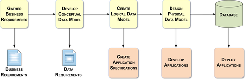
As Figure 8.2 shows, the workflow starts with gathering the business requirements. This is where you talk to the business group and ask what they need for the application.
After gathering requirements, you develop the conceptual data model. For this stage, you need to know what business subjects are being captured in the data requirements, what they mean, where the data is, and what some of the relationships are in that data.
Then you create the logical data model, which is the bulk of the data modeling work. It includes taking what you learned in the business requirements gathering and conceptual data model stages and discerning the detail of the entities and relationships present in the conceptual model. From this you create the application specifications. The whole point of creating a logical model is to make a blueprint that guides the development of your application code and ensures it works correctly.
After creating the logical data model and application specs, the next step is actually designing the physical data model. This includes adding the partitioning, indexing, table spaces, and whatever else is necessary in order to generate optimal performance. This is followed by physically developing the applications.
FIGURE 8.2Data modeling workflow.
Developing the logical data model is an iterative process. Once you have started application development, you may uncover new relationships, algorithms, or dependencies that were not apparent during the first discussions of logical data modeling. This is very common and is not a major problem. In fact, this iterative process is a powerful stepwise refinement of both the logical and physical model that occurs during application development and testing. The end result is a validated physical data model used to implement the business and data requirements in the application.
THE DATA MODEL IS CRITICAL
When consulting, I see cases where the IT group completed all the work to create specifications for their code and reviewed it, but when I ask them for a data model there is a sheepish laugh; they admit that they do not really have one or that they do not have a current one. That is not a good sign. It is important to manage and spec the code within your data model—logically or physically. The code has to operate that data, and you need to save that data model just as you save the specs. The data model is part of the spec; it is a key part of your communication vehicle and your maintenance package.
Where Data Models Are Used
Data models are a key component of relational databases, which are the workhorses of enterprise applications today. There are two primary areas in which relational databases are used—transactional processing (also called operational systems) and BI:
• Transactional processing and operational systems—the class of applications built to support these transactions is ERP systems. These systems process the business transactions and business events that occur throughout an enterprise. When a customer places an order, when an employee is paid, and when a mortgage is processed, all those types of transactions are handled by the operational systems.
• BI applications—these applications are used for reporting, querying, and analytics. This category also includes data warehousing, which is the database backbone to support BI applications.
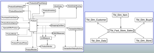
These two uses for relational databases correspond to the two primary modeling approaches used for data: entity-relationship (ER) models and dimensional models. The point of Figure 8.3 is to show them at a high level; the dimensional model on the right is much simpler.
FIGURE 8.3Entity vs dimensional at a glance.
Entity-relationship models are used primarily for transactional processing systems. As the figure shows, the ER model gets very complex with many entities, even for the simple example provided, which is related to a product. In most enterprises, these models get quite complex and contain hundreds, if not thousands, of entities.
Dimensional modeling is used primarily for BI applications. It was designed to represent data more simply in a business context than an ER model. Dimensional models have far fewer entities and are visually easier to understand than ER models. Dimensional models were designed for better BI performance and BI tools; likewise, they were designed to leverage these models for better performance. Although many enterprises have used ER models, we recommend the hybrid dimensional-normalized model discussed in Chapter 6.
There are several reasons why it is important to understand both ER modeling and dimensional modeling to design, develop, and deploy BI applications:
• First, most source systems feeding into a BI environment use ER models. Knowing how these source systems are structured will help in understanding business requirements and performing source systems analysis for data integration.
• Second, ER modeling provides the foundation for many dimensional modeling concepts.
• Finally, hybrid dimensional modeling, the recommended approach to DW design, blends both ER and dimensional modeling.
Entity-Relationship (ER) Modeling Overview
ER modeling is a logical design modeling technique. After the business requirements and data requirements are gathered and you understand the business rules, you will start developing your logical data model.
An ER model is often referred to as a 3NF, or third normal form, or sometimes just a normalized model for short. It is also sometimes referred to as a relational model, which is incorrect. Although it is implemented in a relational database, it is not the sole data modeling technique that could be used in a relational database.
ERP systems nearly always uses ER models. These systems often have thousands of tables, and some even have tens of thousands. Certainly, with that complexity, using a structured approach and technique is critical. Because of the size of these applications, it is important to eliminate data redundancy. The enterprise also likely needs to have its transactions input immediately. With so many tables to deal with, ER models need to enable fast loading and updates.
ER Building Blocks
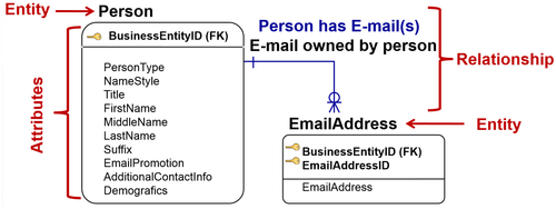
The three building blocks of an ER model are entities, relationships, and attributes (see Figure 8.4).
An entity is a person, place, thing, event, or concept about which the business keeps data. For example, an enterprise keeps track of its products, customers, employees, suppliers, sales, expenses, and interactions with partners, the government, and other people or business entities. The enterprise needs all these things, or entities, to operate and manage its business.
FIGURE 8.4ER modeling building blocks.
Relationships show how the entities are related to one another. Relationships are the logical links between the entities that represent the business rules or constraints. For example, a customer’s relationship to a product is that she buys it; an enterprise’s relationship to an employee is that it pays her. These links have business rules, which are captured in the data model.
An attribute is a distinct characteristic of an entity for which data is maintained. For example, if the entity is a person, the attributes may be birthday, marital status, and address. If the entity is a product, the attributes may be price, color, and size. These attributes are characteristics the enterprise needs to capture in order to understand the business.
The example in Figure 8.4 shows a simple example of two entities, a person and an email address:
• The person has various attributes, starting with type (PersonType), which could categorize a role within the enterprise, such as a salesperson or a manager. Then it shows the person’s title, name, and additional contact information and demographics. All are attributes related to a person. The person entity’s primary key is BusinessEntityID.
• The email address entity simply has the attributes of EmailAddressID and the email address itself. The email address entity’s primary key is a combination of BusinessEntityID and EmailAddressID.
In between these two entities is the relationship. One example of a relationship is that a person can have one or multiple email accounts, but an email account is owned by one person. Similarly, a product has relationships with other entities such as other products, customers, and salespeople. All relationships are defined by particular business rules.
Types of Entities and Attributes
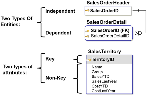
There are two types of entities, independent and dependent:
• Independent entities can survive on their own and do not need any children.
• Dependent entities are child records that need a parent record to exist.
Figure 8.5 shows the SalesOrderHeader entity. It may have one or more SalesOrderDetail entities; each of those line items in the order detail needs to have the SalesOrderHeader entity to exist. This makes them dependent entities. The SalesOrderHeader entity itself is an independent entity.
FIGURE 8.5Entity and attribute types.
There are also two types of attributes in an entity: key or non-key. The figure shows the SalesTerritory entity with a key attribute of TerritoryID and the non-key attributes of Name, Group, SalesYTD, etc. Unlike key attributes, non-key attributes do not uniquely identify an attribute. Similarly, we can have a product with a product ID and the product attributes, or a person with person attributes as shown in Figure 8.4. Keys are important, and will be covered in more detail later in this chapter.
Relationship Cardinality
Cardinality is defined as the number of instances of an entity in a relationship with another entity. There can be one or many instances. For example, with a parent-child relationship, cardinality defines, on both the parent and child sides, how many occurrences can take place between these entities. There are four options, described in Table 8.1: one-to-one, one-to-many, many-to-one, and many-to-many.
In addition to these four types of cardinality, note that relationships can also be recursive. With self-referencing, or recursive, relationships, the same entity can be in both ends of the relationship. In other words, there may be more than one relationship between entities. A parent-child relationship could also have a child-parent relationship, and they do not have to be the same. The classic example of this is an employee who reports to another employee (a manager). So you have an entity with an employee ID, then you would have a second employee ID for the manager, and then that manager has a manager that he reports to, etc. So you could have a relationship that just points to itself.
Types of Relationship Models
An entity-relationship model has four basic types of relationships: identifying, nonidentifying (either optional or mandatory), and many-to-many relationships. Cardinality imposes itself on these various relationships.
Table 8.1
Cardinality
Type
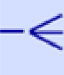
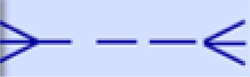
Crow’s Foot Notation
One-to-one—One instance of the first entity, the parent, corresponds to only one instance of the child or the second entity. If you have one, you have to have the other. For example, one employee has one employee ID number.
One-to-many—The example in Figure 8.5 shows the relationship between an order header item and an order detail item. The parent is SalesOrderHeader: there is only one of them. The children are SalesOrderDetail: there can be many of them.
Many-to-one—There is more than one instance of the first entity, the parent, but it corresponds to only one instance of the second entity. For example, there can be many survey responses to one question. Or there are multiple reasons why a person buys one product. The difference between one-to-many and many-to-one depends on what side of the relationship you are looking at. For example, one department has many employees (one-to-many), but many employees work in one department (many-to-one).
Many-to-many—The most complex is the many-to-many relationship. There is more than one instance of the first entity corresponding to more than one instance of the second entity. The classic example of this is a sick patient visiting the doctor. The patient can have many symptoms and diagnoses. There can be many procedures that apply to each of those diagnosis. These are the most complex relationships to implement in a relational database. But there are techniques, covered later under dimensional modeling, that show how to handle them.
A data modeling tool helps to specify the type of these relationships in a data model; it then builds the SQL data definition code corresponding to the relationships’ constraints.
Identifying Relationship
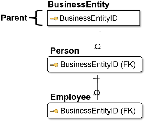
As the name implies, the identifying relationship establishes the parent as a way to identify and classify the child. In this type of relationship, the primary key from the parent migrates through the relationship to become part of the primary key, or identity, of the child. Therefore, the child entity is dependent upon the parent for its identification or classification, and it cannot exist without the parent.
Figure 8.6 shows the highest level entity, BusinessEntity. This entity can define multiple types of entities, such as an organization, asset, or person. BusinessEntity is the top-level parent and identifies the child entity Person, which uses the BusinessEntityID as one of its primary keys. Next, the Employee entity is the child of the Person entity that then defines the Employee entity. Each of these entities has different attributes that are inherited by the children under them, as well as their identity. It is a classic object-oriented development approach called inheritance, and it is a way to reuse attributes and entity characteristics.
Nonidentifying Mandatory Relationship
To understand the nonidentifying mandatory relationship, you need to understand its two aspects, nonidentifying and mandatory:
• It is nonidentifying because the parent entity’s primary key migrates as a non-key attribute to the child but does not identify the child. The non-key attribute means it is a foreign key pointing back to the parent entity. But it is not used as part of the primary key.
• The relationship is mandatory because the child is independent of the parent for its identification, but it cannot exist without a parent.
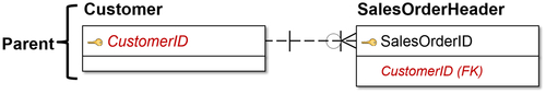
The example in Figure 8.7 shows that Customer is the parent; customers can exist whether they buy a product or not. SalesOrderHeader, which is the child record, migrates from the CustomerID, a non-key attribute, as a foreign key to then point back at Customer. Customer can exist without SalesOrderHeader. However, it is mandatory that SalesOrderHeader has a CustomerID.
The nomenclature on the sales order side shows crow’s feet, which means many orders can be placed by one customer. The circle over the crow’s feet means it is not mandatory. On the other side of the equation, one customer must exist. This is a one-to-many relationship.
Nonidentifying Optional Relationship
In a nonidentifying optional relationship, the parent entity has a primary key that migrates, as a non-key attribute, to the child but does not identify the child. In other words, the child is independent of its parents for its identification. Also, the child may exist without parent information.
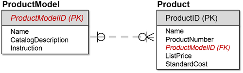
Figure 8.8 shows the parent entity ProductModel, which can exist on its own. ProductModel has ProductModelID as its primary key and some attributes (Name, CatalogDescription, and Instruction).
The child record is the entity Product. The ProductID is its primary key identifying the product entity. It has various attributes, including the ProductModelID, which is the foreign key and migrated from the parent entity. But that ProductModelID is not necessary to identify the product. It may indeed be null, and it does not even need to exist.
FIGURE 8.8Non-identifying optional relationship.
On the child side are the crow’s feet, which means “many,” so one ProductModel can have many Products. There is a circle over the crow’s feet, meaning it is optional.
On the parent side, a single line indicates a “one” relationship, so it is one-to-many (one from the parent, many for the children). The circle indicates that it is optional. There are optional relationships on both sides. Each entity can exist without the other one.
Many-to-Many Relationships
The many-to-many relationship has a nonspecific relationship in which primary keys do not migrate as foreign keys. There must be two verb phrases to explain the relationship because it is many-to-many, representing a relationship for both the parent and child sides. Each phrase must state the rule from the perspective of first the parent to the child and then the child to the parent.
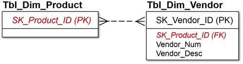
Figure 8.9 is for a company that sells multiple products listed on entity Tbl_Dim_Product with SK_Product_ID as the primary key. It also has an entity of vendor, which produces various product IDs, with other attributes relating to the vendor.
FIGURE 8.9Many-to-many relationship.
The two verb phrases identifying the relationships for this example are:
• A product may be purchased from one or more vendors.
• A vendor may produce one or more products.
This is a classic retailer model. The vendor or supplier produces multiple products, which the company (in this example a retailer) acquires and then resells. The product may be produced by multiple vendors. This makes it a many-to-many relationship, and the nomenclature in the figure shows crow’s feet on either side with no mandatory or optional symbols (circles). The many-to-many relationship is the most difficult to implement in a relational database. The next chapter, on dimensional modeling, will discuss how to simplify that relationship and how to implement it in a dimensional model.
Recursive Relationships
After a many-to-many relationship, one of the more difficult relationships to express in SQL is a recursive relationship. This is a nonidentifying, nonmandatory relationship in which the same entity is both the parent and the child.
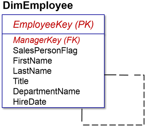
Figure 8.10 shows the entity DimEmployee, with EmployeeKey being the primary key. It has various attributes, including ManagerKey, which is actually another EmployeeKey. So you are an employee, and your manager is also an employee, and that is in the same dimension. That manager is an employee who most likely will have a manager and so on up the organizational structure. The parent entity instance primary key has migrated to the non-key area of the child entity instance.
FIGURE 8.10Recursive relationship.
Each migrating primary key attribute must be given a role name to clarify the attribute’s foreign key role. So we did not simply have EmployeeKey; we could not have the same attribute again called EmployeeKey. In essence, we created and renamed it ManagerKey, which is a foreign key.
This is also referred to as a self-referencing relationship. It is used frequently in ER and dimensional modeling in enterprises because many business relationships are represented by recursive hierarchies. However, it is one of the areas that is difficult to handle in standard SQL code as you are moving up and down a tree, without either custom coding or using a DBMS with added SQL extensions to support this recursive processing.
ER Model Example
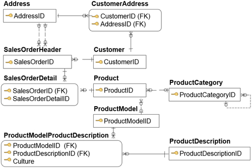
The previous sections have covered the different types of relationships. So how do they all fit together? Figure 8.11 provides a view of how the various relationships and cardinality fit in. Pieces of this example have already appeared in previous figures.
The example shows a business event, in this case a sale being made to a customer who buys various products. SalesOrderHeader defines what the sales transaction is. There is a one-to-many relationship between SalesOrderHeader and SalesOrderDetail. So, a customer can buy one or more products in that order. The crow’s feet signify the “many,” the single line underneath SalesOrderHeader shows “one,” and the circle over the crow’s feet indicates an optional relationship between SalesOrderHeader and the SalesOrderDetail.
Similarly, we have the one-to-many optional relationship between the customer who buys the products and the sales order (Customer to SalesOrderHeader). We have a customer who can exist independent of the sales order, but the sales order must have a customer associated with it. Similarly, SalesOrderDetail is where the products are listed as foreign keys, and we have the one-to-many relationship between Product and SalesOrderDetail. Just like the customer, products can exist outside of the orders, but an order detail line item must have a product.
FIGURE 8.11ER model example.
The figure also shows the example of a product model (ProductModel); Product may have ProductModelID and even multiple ProductModelIDs related to it. ProductModel will then potentially have one-to-many product descriptions (ProductModelProductDescription). In this example, people took out the commonality of product descriptions, which might be used across products, and separated that as a separate entity itself, another one-to-many relationship.
Going back up to Product, the example shows that many products may be related to one category (ProductCategory). “May” is an important distinction, indicated by the circles showing both relationships are optional.
But, ProductCategoryID shows multiple levels of product categories that a product can be grouped in. This means that a product can be grouped in one set, a number of products grouped into a product category, and the product category itself could have a hierarchy. In the lower right-hand corner of that product category entity is a recursive, or self-referencing, relationship, which indicates it could move up the hierarchy.
Finally, above SalesOrderHeader, the example shows that there could be multiple addresses associated with the sales order. There could be ship-to addresses, bill-to addresses, and other related addresses. There is also a specific customer address related to a customer ID, and there might be multiple addresses related to it. That customer address is then related to the business entity address that is set up in the upper left-hand corner.
The example shows that a simple sales order has a number of relationships; this is how an entity relationship model is built with the various relationships discussed in this chapter.
Keys
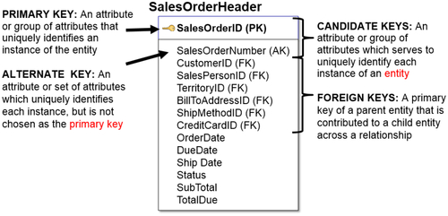
Learning about keys gets you closer to learning how to build a physical data model. This section describes the process of using a logical model to decide which attributes are used for keys. There are four types of keys: candidate, primary, alternate, and foreign.
Candidate Key
The candidate key is the attribute or group of attributes that can uniquely identify each instance of an entity.
There may be more than one key that can accomplish this. This is often the case where there is a transaction-related key. In Figure 8.12SalesOrderHeader has the candidate key of SalesOrderNumber, which may be generated by the transaction, assumed to be unique. You would also potentially have SalesOrderID, which may be an identity key or a surrogate key that is generated to uniquely identify the transaction later on.
FIGURE 8.12Key types.
Primary and Alternate
The primary key (PK) is the attribute or group of attributes that is chosen to uniquely identify each instance of an entity. If there is a list of candidate keys, then one needs to be designated as the PK.
The alternate key (AK) is the attribute or group of attributes that is not chosen as a primary key to uniquely identify each instance of an entity. There are alternate keys when there are more than one candidate key that may be chosen to be the primary key.
It is important to pick a primary key that is the most efficient for the application. The decision between which key will be primary and which will be alternate in a BI application is usually based on which one is best for querying, especially when many joins are used. The best key in this scenario has a numeric or integer data type, because it is much more efficient for indexing, sorting, and joining.
Foreign Key
The foreign key (FK) is a primary key of a parent entity that is contributed to a child entity across a relationship. That means there are attributes, such as customer ID, salesperson ID, territory ID, and bill-to address ID, that are primary keys in various other entities. There is a customer entity and a salesperson entity that have those keys as primary keys. They are placed in the sales order header, so they identify who bought it, who sold it, and what territory it was bought in. This is the quick way to be able to join those entities and collect the attributes that are related to the foreign key, which could be customer, salesperson, territory, or something else.
Referential Integrity
Referential integrity (RI) is a term used with relational databases to describe the integrity of the business relationships represented in the schema. It ensures that relationships between tables remain consistent. As it applies to a logical data model, RI encompasses the rules that determine the actions that are taken when parent or child rows are inserted, updated, or deleted in a database. None of these actions—inserting, updating or deleting—can violate the relationships that have been defined.
RI includes enforcing relationship cardinality rules (e.g., one-to-many, many-to-one, etc.) and the various types of relationship models (e.g., identifying, nonidentifying optional, nonidentifying mandatory, and many-to-many). There are two primary approaches to implementing RI:
1. Leverage database functionality, such as foreign key constraints and triggers. Using this approach, when data is inserted, updated, or deleted in the database, it will enforce referential integrity.
2. Develop data integration processes such as ETL code. With this approach, the data integration processes will examine the data that is being inserted, updated, or deleted; determine what the relationship rules are for processing; and then take the appropriate action. This is the best practice.
The first approach appears to be the most straightforward because it uses prebuilt database functionality without the need for any custom coding. If the relationships are properly implemented in the database, it is guaranteed that referential integrity will be enforced. There are two significant drawbacks to this approach, however:
• First, database performance can be adversely affected when using this approach.
• Second, and most importantly, database inserts, updates, and deletions can only occur if all the data related to the relationships is available at the same time. Although this condition is met in transaction processing, it is often not the case in BI applications where data is being gathered from many different source systems that have different update frequencies and operate under different business rules. This means that if you use the first method, many BI-related database updates might not be completed, which then results in significant amounts of data never being updated or made available for analysis. Under these conditions, it is best to choose the second approach of developing code.
For these reasons, transactional applications commonly enforce referential integrity by using the first method of relying on the database. In BI implementations, the best practice has been the second method of developing data integration code that can systematically process data under agreed-upon rules to enforce referential integrity. An emerging best practice has been to define database referential integrity and then to turn it off during loads if ETL-enforced RI is needed to load data.
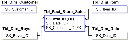
FIGURE 8.13Referential integrity.
Figure 8.13 shows a fact table for store sales—Tbl_Fact_Store_Sales. Four entities surround Tbl_Fact_Store_Sales with the following relationships:
• One-to-many relationship between the entity table item Tbl_Dim_Item, which is the product being sold at the store.
• One-to-many relationship between the entity of date Tbl_Dim_Date, which is when the product was sold at the store.
• One-to-many relationship between the entity of customer Tbl_Dim_Customer, which is the customer who bought the product.
Within Tbl_Fact_Store_Sales are three foreign keys that are used to define the primary key of that particular entity. Any of those three entities (SK_Item_ID, SK_Date_ID, or SK_Customer_ID) can exist on their own. But you cannot have a store sale without selling a product to a customer at a particular point in time. That is how referential integrity is defined. The store sale cannot occur unless those three foreign keys are brought into the entity.
Additionally, the example shows the buyer (Tbl_Dim_Buyer), which is a one-to-many relationship, but is optional in this case. There could be a buyer who actually bought the product from another company, or the purchase could have been in another business transaction. So, this is an optional relationship that is not enforced through referential integrity.
Normalization
The ER model is used for transactional systems primarily because it minimizes data redundancy and ensures data integrity. The approach to reduce redundancy is called normalization, which is a formal data modeling approach to examining and validating a model and putting it into a particular normalized form. The ER model is often called a third normal form (3NF) or a normalized model. The advantage of this process is that each attribute that belongs to an entity is going to be assigned a unique position within the data model. The goal is to have minimal or no redundancy throughout the data model, and normalization helps achieve this goal.
The downside of normalization is that it can adversely affect performance and deadlines if strictly enforced. ERP systems can have tens of thousands of tables. This, of course, has an impact on performance anyway based on the number of joins and tables that have to be updated. Adding the effort of normalizing a large model can take an inordinate amount of time to design and to code.
Normalization Levels
There are precise definitions and approaches toward normalizing a database. Edgar Frank Codd, who invented the relational model for database management, identified the normal forms as different states of the normalized relational data model. Those levels are defined as:
• First normal form (1NF), which has no repeating groups within it.
• Second normal form (2NF), which has no partial-key dependencies.
• Third normal form (3NF), which has no non-key interdependencies.
• Fourth normal form (4NF), which has no independent multiple relationships.
• Fifth normal form (5NF), which has no semantically-related multiple relationships.
Like cardinality, normalization is an obscure concept that requires close examination to really understand the differences. Fortunately, this classic, yet challenging modeling technique leads to whatever level of normalization is required. The application of the normalization rules are cumulative from 1NF to 5NF.
Most operational systems or transactional systems are implemented in the third normal form. 3NF is considered the best practice in that it enables transactional integrity while balancing complexity and performance. Although there are higher levels of normalization, they are rarely used in transactional systems and never used in BI applications.
Normalizing an Entity
There are three steps to develop a third normal form database. They are shown at a high level below, and then in further detail in the subsequent sections.
1. 1NF—Eliminate repeating groups. Make a separate table for each set of attributes (in essence, this is creating an entity). Identify a primary key for each table. If you cannot define a primary key, then you have not split up the tables into the sets of related attributes creating an entity, and you need to repeat this step.
2. 2NF—Eliminate redundant data stored in different entities. If an attribute depends on anything other than the primary key (could be a compound key), then remove it as a separate table.
3. 3NF—Eliminate non-key interdependencies. If you have defined the primary key and the keys within that, then all the attributes in that entity need to be related to that key. For example, if you have customer or product, you can only have attributes that are related to the customer or the product within the entity. Otherwise, remove them and put them into a separate table, as they are most likely separate entities. With these steps completed, you have defined a 3NF schema.
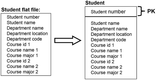
First Normal Form—1NF
The first step to ultimately normalize a database to third normal form is to eliminate repeating groups, creating a first normal form.
Refer to Figure 8.14 and ask the following question for each attribute: does this attribute occur more than once for any instance?
• If it does not, then you have no repeating groups, and you can move on.
FIGURE 8.141NF example.
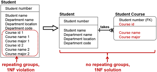
FIGURE 8.151NF example continued.
• If it does, you need to:
• Build a new entity.
• Move all the repeating attributes to the new entity.
• Set the attributes for the new entity’s primary key.
• Build an identifying relationship from the original entity (the one that had the repeating groups to begin with) to the new entity, where you moved those repeating attributes.
As shown in Figure 8.15, you slowly decompose the entities until you have no repeating attributes, so each entity stands alone by itself.
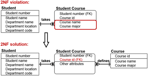
Second Normal Form—2NF
The second step is to eliminate redundant data and get into second normal form (see Figure 8.16). If attributes are not dependent on the primary key, place them into a separate entity. For only those entities that have a primary key that is a composite key, ask the following of each non-key attribute: is this attribute dependent on part of the primary key?
FIGURE 8.162NF example.
• If it is not, then there are no partial-key dependencies.
• If it is, then you need to:
• Build a new entity.
• Move out all the attributes that have the following same partial-key dependency to the new entity.
• Use the dependent attribute as a key or determine a better primary key.
• Build, name, and identify a relationship from the new entity pointing back to the original entity that had the partial-key dependencies.
As Figure 8.16 shows, a stepwise refinement further decomposes the entities, so they can stand on their own.
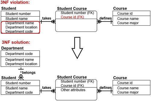
Third Normal Form—3NF
The final step is to eliminate the columns not dependent on the key, which creates the third normal form as shown in Figure 8.17. For each non-key attribute, ask the following: does this attribute depend on some other non-key attribute?
• If it does not, then there are no non-key interdependencies.
• But if it does, once again, you need to:
• Build a new entity to contain all attributes with this same non-key dependency.
• Use the dependent attribute as the primary key.
• Build and name a nonidentifying, nonmandatory (meaning optional) relationship from the new entity back to the original entity.
FIGURE 8.173NF example.
So the third step, to recap, is to decompose an attribute and spin it off when there are attributes that depend on the non-key attributes. Attributes that are related to one another get split out into their own entity.
After the three normalization steps, you reach the third normal form data model, which is generally the area of normalization that is needed to support enterprise applications.
ER Model Recap
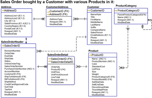
The examples up to this point have shown the various building blocks of the ER model. See Figure 8.18 to see how it all comes together with the attributes, not just the entity and the primary keys, defined.
The example shows a sales order with various products purchased by a customer. It shows SalesOrderHeader, which has the ID (the primary key) and various attributes related to the order ship date, due date, status of the order, purchase order number, the account number, the customer ID, etc. It has a one-to-many relationship with SalesOrderDetail, which has the product ID, order quantity, unit price, and other items related to line item details of the sale.
Putting it into real-world terms helps put the elements of the example into perspective, so you can see how it all comes together:
• The customer order, which is SalesOrderHeader, has a one-to-many relationship to SalesOrderDetail, because a customer makes the purchase, creating the sale.
• There are attributes related to the Customer entity, because customers are people with attributes such as first name, last name, and email address.
• The sales order, SalesOrderDetail, has attributes, such as quantity ordered and unit price.
FIGURE 8.18ER model recap.
• The Product entity shows the details of a typical product, such as color, standard cost, list price, size, and weight.
Taking the entity model and expanding it to include the attributes shows how much sense the model makes:
• There is Product, which becomes part of the product category that was a self-referencing (or recursive) relationship, where multiple products are grouped in product categories that are then grouped in product categories themselves.
• There is Customer, which has a customer address, and some attributes related to it.
• There is the generic Address, which is referenced by the CustomerAddress and also referenced by SalesOrderHeader, because the order header has multiple related addresses (ship-to address, bill-to address, etc.)
Although data modeling often seems esoteric, it is an effective data design technique to represent data in its business context. Reviewing the above example illustrates how the company sales can be represented with entities such as Customer, Product, Address, SalesOrderHeader, and SalesOrderDetail.
Limits and Purpose of Normalization
There are issues with normalization. The structures can get very complex when ERP applications have thousands of tables. It can be difficult to understand a model that large. Of course, performance can be an issue: querying is especially difficult when you have so many tables to join.
Fortunately, for those of us working in BI, most ER modeling is done for transactional systems, so we do not have to create models for thousands of tables. But it is good to understand the model, because we need to access, reference, and use those enterprise applications, and we should know how they are constructed.
Understanding ER modeling also helps you learn dimensional modeling, because the entity, relationship, and attributes are all building blocks for the dimensional model. This will be covered in the next chapter.
The obvious question is why you should go through the process of normalization, especially to third normal form. The reason is that normalization creates the cleanest entity relationship model available. The entities only have attributes related to the entities themselves, and you can establish relationships between the entities that make sense. This makes it easier to define the data, and the relationships and interdependencies are more clearly identified. Because only the attributes within the entities exist, the ambiguities are resolved. The data model can be more flexible, and it is easier to maintain, not only because of the lack of redundancy, but also because the entities, the attributes, and the relationships are clearly defined.