
Activity Diagrams
Like a state diagram, an activity diagram models aspects of system behavior. Unlike a state diagram, an activity diagram models an object’s workflow (sequence of events) during program execution. An activity diagram models the actions the object will perform and in what order. Recall that we used UML activity diagrams to illustrate the flow of control for the control statements presented in Chapters 4 and 5.
Figure 22.14 models the actions involved in executing a BalanceInquiry transaction. We assume that a BalanceInquiry object has been initialized and assigned a valid account number (that of the current user), so the object knows which balance to retrieve. The diagram includes the actions that occur after the user selects a balance inquiry from the main menu and before the ATM returns the user to the main menu—a BalanceInquiry object does not perform or initiate these actions, so we do not model them here. The diagram begins with retrieving the available balance of the user’s account from the database. Next, the BalanceInquiry retrieves the total balance of the account. Finally, the transaction displays the balances on the screen. This action completes the execution of the transaction.
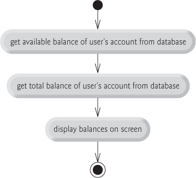
Fig. 22.14. Activity diagram for a BalanceInquiry transaction.
The UML represents an action in an activity diagram as an action state modeled by a rectangle with its left and right sides replaced by arcs curving outward. Each action state contains an action expression—for example, “get available balance of user’s account from database”—that specifies an action to be performed. An arrow with a stick arrowhead connects two action states, indicating the order in which the actions represented by the action states occur. The solid circle (at the top of Fig. 22.14) represents the activity’s initial state—the beginning of the workflow before the object performs the modeled actions. In this case, the transaction first executes the “get available balance of user’s account from database” action expression. Second, the transaction retrieves the total balance. Finally, the transaction displays both balances on the screen. The solid circle enclosed in an open circle (at the bottom of Fig. 22.14) represents the final state—the end of the workflow after the object performs the modeled actions.
Figure 22.15 shows an activity diagram for a Withdrawal transaction. We assume that a Withdrawal object has been assigned a valid account number. We do not model the user selecting a withdrawal from the main menu or the ATM returning the user to the main menu because these are not actions performed by a Withdrawal object. The transaction first displays a menu of standard withdrawal amounts (Fig. 22.3) and an option to cancel the transaction. The transaction then inputs a menu selection from the user. The activity flow now arrives at a decision symbol. This point determines the next action based on the associated guard conditions. If the user cancels the transaction, the system displays an appropriate message. Next, the cancellation flow reaches a merge symbol, where this activity flow joins the transaction’s other possible activity flows (which we discuss shortly). A merge can have any number of incoming transition arrows, but only one outgoing transition arrow. The decision at the bottom of the diagram determines whether the transaction should repeat from the beginning. When the user has canceled the transaction, the guard condition “cash dispensed or user canceled transaction” is true, so control transitions to the activity’s final state.
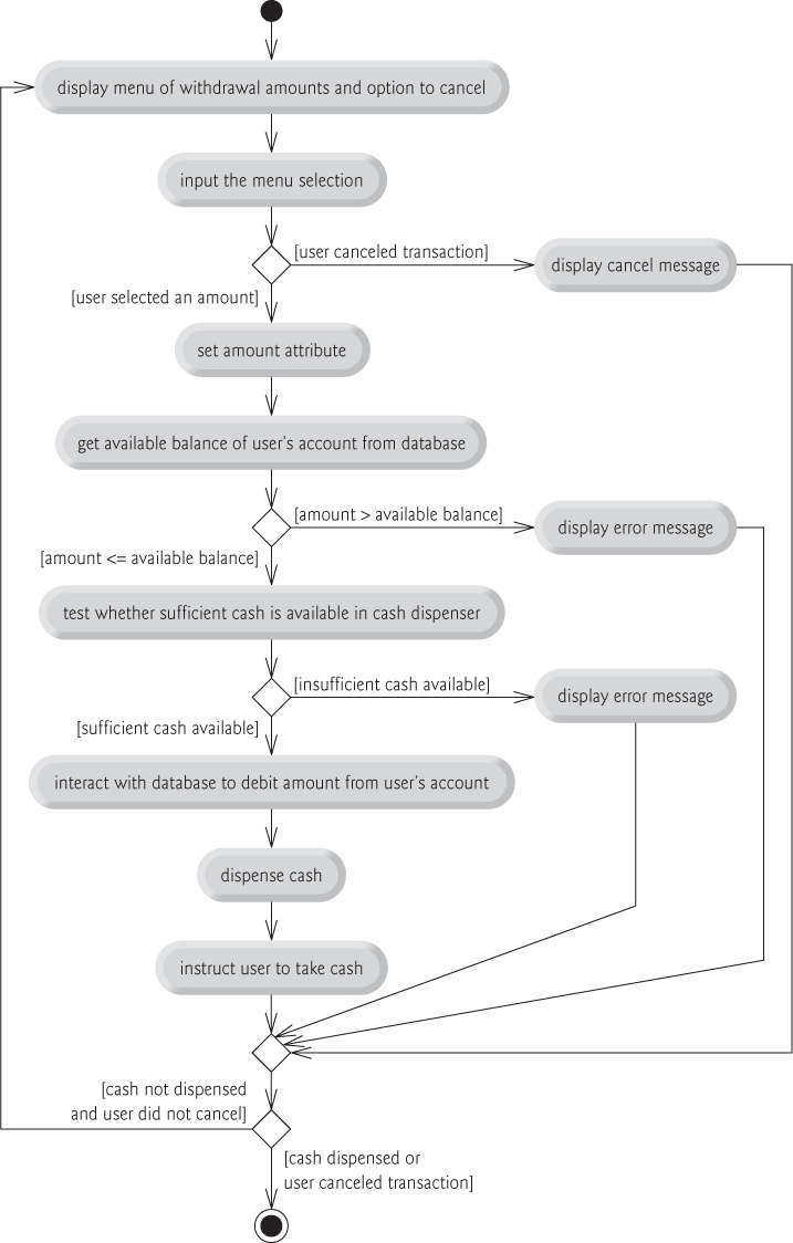
Fig. 22.15. Activity diagram for a Withdrawal transaction.
If the user selects a withdrawal amount from the menu, the transaction sets amount (an attribute of class Withdrawal originally modeled in Fig. 22.12) to the value chosen by the user. The transaction next gets the available balance of the user’s account (i.e., the availableBalance attribute of the user’s Account object) from the database. The activity flow then arrives at another decision. If the requested withdrawal amount exceeds the user’s available balance, the system displays an appropriate error message informing the user of the problem. Control then merges with the other activity flows before reaching the decision at the bottom of the diagram. The guard decision “cash not dispensed and user did not cancel” is true, so the activity flow returns to the top of the diagram, and the transaction prompts the user to input a new amount.
If the requested withdrawal amount is less than or equal to the user’s available balance, the transaction tests whether the cash dispenser has enough cash to satisfy the withdrawal request. If it does not, the transaction displays an appropriate error message and passes through the merge before reaching the final decision. Cash was not dispensed, so the activity flow returns to the beginning of the activity diagram, and the transaction prompts the user to choose a new amount. If sufficient cash is available, the transaction interacts with the database to debit the withdrawal amount from the user’s account (i.e., subtract the amount from both the availableBalance and totalBalance attributes of the user’s Account object). The transaction then dispenses the desired amount of cash and instructs the user to take the cash that is dispensed. The main flow of activity next merges with the two error flows and the cancellation flow. In this case, cash was dispensed, so the activity flow reaches the final state.
We’ve taken the first steps in modeling the ATM system’s behavior and have shown how an object’s attributes participate in the object’s activities. In Section 22.7, we investigate the operations of our classes to create a more complete model of the system’s behavior.