
Modeling Classes
The UML enables us to model, via class diagrams, the ATM system’s classes and their interrelationships. Figure 22.6 represents class ATM. Each class is modeled as a rectangle with three compartments. The top compartment contains the name of the class, centered horizontally and in boldface. The middle compartment contains the class’s attributes. (We discuss attributes in Section 22.5 and Section 22.6.) The bottom compartment contains the class’s operations (discussed in Section 22.7). In Fig. 22.6 the middle and bottom compartments are empty, because we’ve not yet determined this class’s attributes and operations.

Fig. 22.6. Representing a class in the UML using a class diagram.
Class diagrams also show the relationships among the classes of the system. Figure 22.7 shows how our classes ATM and Withdrawal relate to one another. For the moment, we choose to model only this subset of classes for simplicity; we present a more complete class diagram later in this section. Notice that the rectangles representing classes in this diagram are not subdivided into compartments. The UML allows the suppression of class attributes and operations in this manner, when appropriate, to create more readable diagrams. Such a diagram is said to be an elided diagram—one in which some information, such as the contents of the second and third compartments, is not modeled. We’ll place information in these compartments in Section 22.5 and Section 22.7.

Fig. 22.7. Class diagram showing an association among classes.
In Fig. 22.7, the solid line that connects the two classes represents an association—a relationship between classes. The numbers near each end of the line are multiplicity values, which indicate how many objects of each class participate in the association. In this case, following the line from one end to the other reveals that, at any given moment, one ATM object participates in an association with either zero or one Withdrawal objects—zero if the current user is not currently performing a transaction or has requested a different type of transaction, and one if the user has requested a withdrawal. The UML can model many types of multiplicity. Figure 22.8 lists and explains the multiplicity types.

Fig. 22.8. Multiplicity types.
An association can be named. For example, the word Executes above the line connecting classes ATM and Withdrawal in Fig. 22.7 indicates the name of that association. This part of the diagram reads “one object of class ATM executes zero or one objects of class Withdrawal.” Association names are directional, as indicated by the filled arrowhead—so it would be improper, for example, to read the preceding association from right to left as “zero or one objects of class Withdrawal execute one object of class ATM.”
The word currentTransaction at the Withdrawal end of the association line in Fig. 22.7 is a role name, which identifies the role the Withdrawal object plays in its relationship with the ATM. A role name adds meaning to an association between classes by identifying the role a class plays in the context of an association. A class can play several roles in the same system. For example, in a school personnel system, a person may play the role of “professor” when relating to students. The same person may take on the role of “colleague” when participating in a relationship with another professor, and “coach” when coaching student athletes. In Fig. 22.7, the role name currentTransaction indicates that the Withdrawal object participating in the Executes association with an object of class ATM represents the transaction currently being processed by the ATM. In other contexts, a Withdrawal object may take on other roles (e.g., the previous transaction). Notice that we do not specify a role name for the ATM end of the Executes association. Role names in class diagrams are often omitted when the meaning of an association is clear without them.
In addition to indicating simple relationships, associations can specify more complex relationships, such as objects of one class being composed of objects of other classes. Consider a real-world automated teller machine. What “pieces” does a manufacturer put together to build a working ATM? Our requirements document tells us that the ATM is composed of a screen, a keypad, a cash dispenser and a deposit slot.
In Fig. 22.9, the solid diamonds attached to the association lines of class ATM indicate that class ATM has a composition relationship with classes Screen, Keypad, CashDispenser and DepositSlot. Composition implies a whole/part relationship. The class that has the composition symbol (the solid diamond) on its end of the association line is the whole (in this case, ATM), and the classes on the other end of the association lines are the parts—in this case, classes Screen, Keypad, CashDispenser and DepositSlot. The compositions in Fig. 22.9 indicate that an object of class ATM is formed from one object of class Screen, one object of class CashDispenser, one object of class Keypad and one object of class DepositSlot. The ATM has a screen, a keypad, a cash dispenser and a deposit slot. The has-a relationship defines composition. (We’ll see in Section 23.3 that the is-a relationship defines inheritance.)
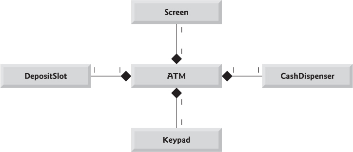
Fig. 22.9. Class diagram showing composition relationships.
According to the UML specification, composition relationships have the following properties:
1. Only one class in the relationship can represent the whole (i.e., the diamond can be placed on only one end of the association line). For example, either the screen is part of the ATM or the ATM is part of the screen, but the screen and the ATM cannot both represent the whole in the relationship.
2. The parts in a composition relationship exist only as long as the whole, and the whole is responsible for creating and destroying its parts. For example, the act of constructing an ATM includes manufacturing its parts. Furthermore, if the ATM is destroyed, its screen, keypad, cash dispenser and deposit slot are also destroyed.
3. A part may belong to only one whole at a time, although the part may be removed and attached to another whole, which then assumes responsibility for the part.
The solid diamonds in our class diagrams indicate composition relationships that fulfill these three properties. If a has-a relationship does not satisfy one or more of these criteria, the UML specifies that hollow diamonds be attached to the ends of association lines to indicate aggregation—a weaker form of composition. For example, a personal computer and a computer monitor participate in an aggregation relationship—the computer has a monitor, but the two parts can exist independently, and the same monitor can be attached to multiple computers at once, thus violating the second and third properties of composition.
Figure 22.10 shows a class diagram for the ATM system. This diagram models most of the classes that we identified earlier in this section, as well as the associations between them that we can infer from the requirements document. [Note: Classes BalanceInquiry and Deposit participate in associations similar to those of class Withdrawal, so we’ve chosen to omit them from this diagram to keep it simple. In Section 23.3, we expand our class diagram to include all the classes in the ATM system.]

Fig. 22.10. Class diagram for the ATM system model.
Figure 22.10 presents a graphical model of the structure of the ATM system. This class diagram includes classes BankDatabase and Account and several associations that were not present in either Fig. 22.7 or Fig. 22.9. The class diagram shows that class ATM has a one-to-one relationship with class BankDatabase—one ATM object authenticates users against one BankDatabase object. In Fig. 22.10, we also model the fact that the bank’s database contains information about many accounts—one object of class BankDatabase participates in a composition relationship with zero or more objects of class Account. Recall from Fig. 22.8 that the multiplicity value 0..* at the Account end of the association between class BankDatabase and class Account indicates that zero or more objects of class Account take part in the association. Class BankDatabase has a one-to-many relationship with class Account—the BankDatabase contains many Accounts. Similarly, class Account has a many-to-one relationship with class BankDatabase—there can be many Accounts contained in the BankDatabase. [Note: Recall from Fig. 22.8 that the multiplicity value * is identical to 0..*. We include 0..* in our class diagrams for clarity.]
Figure 22.10 also indicates that if the user is performing a withdrawal, “one object of class Withdrawal accesses/modifies an account balance through one object of class BankDatabase.” We could have created an association directly between class Withdrawal and class Account. The requirements document, however, states that the “ATM must interact with the bank’s account information database” to perform transactions. A bank account contains sensitive information, and systems engineers must always consider the security of personal data when designing a system. Thus, only the BankDatabase can access and manipulate an account directly. All other parts of the system must interact with the database to retrieve or update account information (e.g., an account balance).
The class diagram in Fig. 22.10 also models associations between class Withdrawal and classes Screen, CashDispenser and Keypad. A withdrawal transaction includes prompting the user to choose a withdrawal amount and receiving numeric input. These actions require the use of the screen and the keypad, respectively. Furthermore, dispensing cash to the user requires access to the cash dispenser.
Classes BalanceInquiry and Deposit, though not shown in Fig. 22.10, take part in several associations with the other classes of the ATM system. Like class Withdrawal, each of these classes associates with classes ATM and BankDatabase. An object of class BalanceInquiry also associates with an object of class Screen to display the balance of an account to the user. Class Deposit associates with classes Screen, Keypad and DepositSlot. Like withdrawals, deposit transactions require use of the screen and the keypad to display prompts and receive input, respectively. To receive deposit envelopes, an object of class Deposit accesses the deposit slot.
We’ve now identified the classes in our ATM system (although we may discover others as we proceed with the design and implementation). In Section 22.5, we determine the attributes for each of these classes, and in Section 22.6, we use these attributes to examine how the system changes over time. In Section 22.7, we determine the operations of the classes in our system.