Chapter 11
Robot Applications
11.1 General Considerations in Robot Applications
In this chapter we consider how robots are applied in industry. The applications can be divided into seven major categories. Before examining these seven categories, it is appropriate to discuss some of the general considerations in robotic applications.
General application characteristics
There are certain general characteristics of an industrial situation which tend to make the installation of a robot economical and practical. These general characteristics include the following.
1. Hazardous or uncomfortable working conditions. In job situations where there are potential dangers or health hazards due to heat, radiation, or toxicity, or where the workplace is uncomfortable and unpleasant, a robot should be considered as a substitute for the human worker. This sort of application has a high probability for worker acceptance of the robot. Examples of these job situations include hot forging, die casting, spray painting, and foundry operations.
2. Repetitive tasks. If the work cycle consists of a sequence of elements which do not vary from cycle to cycle, it is possible that a robot could be programmed to perform the task. This is especially likely if the task is accomplished within a limited workspace. Pick-and-place operations and machine loading are obvious examples of repetitive tasks.
3. Difficult handling. If the workpart or tool involved in the operation is awkward or heavy, it might be possible for a robot to perform the task. Operations involving the handling of heavy workparts are a good example of this case. A human worker would need some form of mechanical assistance to lift the part, which would add to the production cycle time. Some industrial robots are capable of lifting payloads weighing several hundred (or even more than a thousand) pounds.
4. Multishift operation. If the initial investment cost of the robot can be spread over two or three shifts, the labor savings will result in a quicker payback. This could mean the difference between whether or not the investment can be justified. Plastic injection molding and other processes which must be operated continuously are examples of multishift robot applications.
Selecting the right applications
Not all robot installations have been successful. There are enough case histories of misapplications, poorly selected equipment, and nonacceptance by factory personnel to make a prospective user very careful, especially in an initial application. The ideal application would be one which possessed the four general characteristics described in the preceding section. The candidate for robot installations should be subjected to the same kinds of economic criteria as any other investment proposal concerned with productivity improvement or cost reduction. If at all possible, the application should be a simple one, especially on a first robot installation, where success is important for general acceptance of the technology.
The General Electric Company uses the following criteria in performing a plant survey in search of practical and economical robot applications[1]:
Simple repetitive operations are needed.
Cycle times are greater than 5s.
Parts can be delivered in proper location and orientation.
Part weight is suitable (1100 Ib is typically used as the upper limit).
No inspection is required.
One or two persons can be replaced in a 24-hour period.
Setups and changeovers are not frequent.
If the potential application meets all of these criteria, they know they have a prime candidate.
Application areas for industrial robots
Industrial robots have been applied to a great variety of production situations. For purposes of organization, we will divide the applications into the following seven categories:
1. Material transfer
2. Machine loading
3. Welding
4. Spray coating
5. Processing operations
6. Assembly
7. Inspection
In Sections 11.2 through 11.8 we explore the various applications within these seven categories.
11.2 Material Transfer
Material transfer applications are those in which the robot is used to move work-parts from one location to another. In some cases a reorientation of the part may be required in this material handling function. Examples of material transfer robot operations include the following:
Simple pick-and-place operations
Transfer of workparts from one conveyor to another conveyor (basically a pick-and-place task)
Palletizing operations, in which the robot takes parts from a conveyor and loads them onto a pallet in a required pattern and sequence
Stacking operations, similar to palletizing
Loading parts from a conveyor into cartons or boxes (similar to palletizing)
Depalletizing operations, in which the robot takes parts which are arranged on a pallet and loads them onto a conveyor
Material transfer operations are often among the easiest and most straightforward of robot applications (e.g., pick-and-place, transfer from conveyor to conveyor).
Figure 11.1 Prab Model E robot stacks automobile windshield glass in material transfer application. (Courtesy of Prab Conveyors, Inc.)
Robots used for these tasks usually possess a relatively low level of technological sophistication. However, in other cases (e.g., palletizing, depalletizing, etc.), the motion pattern required of the robot can become somewhat complicated. For example, in palletizing, each part must be positioned in its own location on the pallet for each layer, and often multiple layers must be stacked on the pallet. The programming necessary to execute such a motion sequence can become quite involved unless a computer controlled robot is used.
Figure 11.1 shows a Prab Model E performing a typical material transfer application. The robot is used to stack automobile windshield glass with vacuum-actuated grippers.
11.3 Machine Loading
Machine loading applications are material handling operations in which the robot is required to supply a production machine with raw workparts and/or to unload finished parts from the machine. Machine loading is distinguished from a material transfer operation by the fact that the robot works directly with the processing equipment. In material transfer functions, it does not.
In the typical application, the robot would grasp a raw workpart from a conveyor and load it into the machine. In some cases, the robot holds the part in position during processing. When processing is completed, the robot unloads the part from the machine and places it onto another conveyor.
Production operations in which robots have been successfully applied to perform the machine loading and unloading function include the following:
Injection (plastic) molding
Transfer (plastic) molding
Hot forging
Upsetting or upset forging
Stamping press operations
Machining operations such as turning and milling
In some of these operations (die casting and plastic molding), the robot only unloads the finished parts. For machining processes, the robot both loads and unloads the machine tool. In upsetting and stamping operations, the robot holds the workpart while it is being processed by the machine.
Some machine loading applications consist of several processing machines in a manufacturing cell, with the robot tending two, three, or even four separate machines. One of the more recent innovations in machine loading applications is to form a flexible manufacturing system using several robots to augment the conveyor system normally used in these production cells.
Example 11.1
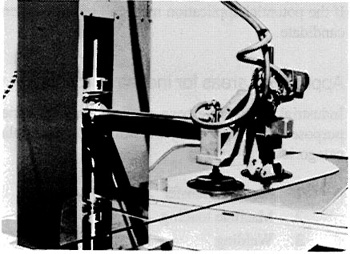
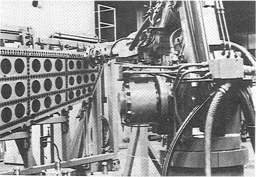
In this example, a Cincinnati Milacron T3 robot is used to service two turning centers and an automatic inspection station. A portion of the work cell is shown in Figure 11.2. Parts enter the cell as raw castings and leave completely machined and inspected. The sequence of work cycle activities is as follows:
1. The robot picks up a raw workpart from the pallet on the conveyor and takes it to the first turning center (not shown in Figure 11.2). The robot enters from the rear of the machine, removes the part just finished, and loads the raw part.
2. The robot transfers the part just completed at the first machine to an automatic gaging station. If the part is determined to be within tolerance, the robot transfers it to the second turning center, ready for loading.
3. The finished part is unloaded from the second machine and the part just gaged from the first machine is loaded. The unloading and loading take place from the rear as illustrated in Figure 11.2.
4. The robot takes the part just finished from the second machine and carries it to the automatic gaging station. If the part is within tolerance, it is placed on the pallet.
The robot is then ready to pick up another raw casting and repeat the work cycle. An interesting feature of this application is that the robot performs the loading and loading from the rear of each machine in the cell. This leaves the front of the machines clear for tool replacement, access to controls, and observation.
Figure 11.2 Cincinnati Milacron T3 robot in machine loading application. (Courtesy of Cincinnati Milacron, Inc.)
11.4 Welding
The welding processes are a very important application area for industrial robots. The applications logically divide into two basic categories, spot welding and arc welding.
Spot welding
Spot welding is a process in which metal parts (sheets or plates) are fused together at localized points by passing a large electric current through the two parts at the points of contact. The process is implemented by means of electrodes which squeeze the parts together and conduct the current to the contact point. The typical pair of electrodes have the form of tongs, which can conveniently be mounted on a large robot’s wrist as the end effector. Using the welding “gun,” as the electrode assembly is sometimes called, the robot accomplishes a spot weld by means of the following sequence:
1. Position the welding gun in the desired location against the two pieces (prior fixturing or matching of the pieces is required).
2. Squeezing the two electrodes against the mating pieces.
3. Weld and hold, when the current is applied to cause heating and fusion of the two surfaces in contact.
4. Release and cool. The electrodes open and sufficient time is allowed to cool the electrodes in anticipation of the next spot weld. (Usually, water is circulated within the electrodes to speed the cooling.)
This is a sequence which has become an ideal task for a point-to-point robot.
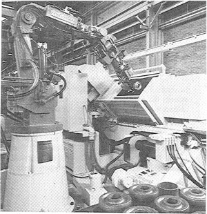
Spot welding has become one of the largest application areas for industrial robots, especially in the automotive industry. During the late 1960s, the first spot welding robots had been installed for producing the Vega model automobile. Today, nearly all automobile manufacturers are using robots for spot welding car bodies. The robot population for this purpose numbers over 1200 units. Other applications for which spot welding robots are used include motorcycle and bicycle frames, truck cabs, and appliances.
Figure 11.3 shows an automobile body welding line in which spot welding is performed automatically by Unimate Model 4000s. Robots have made a fundamental change in the way automobiles are assembled, as the following case study illustrates.
Figure 11.3 Unimate 4000 series robots in spot welding application on automobile assembly line. (Courtesy of Unimation, Inc.)
Example 11.2
A relatively recent example of a spot welding robot automotive line is Chrysler’s Robogate System [13]. This system was installed in 1979 in the company’s Belvidere, Illinois, assembly plant to produce the Plymouth Horizon and Dodge Omni subcompact models. The Robogate is really a giant clamping fixture used to hold the car’s underbody panel and two sides to ensure dimensional stability during tack welding. The tack welding operations are performed by eight Unimate robots. Three of these robots are mounted on each side (a total of six Unimate 4000 models) and two more robots (Unimate 2000 models) are mounted vertically above.
Following the Robogate, four more Unimate 4000s perform spot welding around the door sills and openings. After this section, the car bodies flow through the “respot” line, where over 700 spot welds are accomplished by 24 more Unimate Model 4000 robots.
The plant, using a total of 36 spot welding robots in its car body assembly operations, is capable of a production rate of 75 vehicles per hour. Two different body styles, a four-dour sedan and a two-door coupe, are produced on the line. Control over the system is accomplished by a programmable controller which keeps track of which body styles are at the various stations so that each robot will perform the appropriate weld sequence for that style.
Arc welding
Several types of continuous arc welding processes can be accomplished by industrial robots capable of continuous-path operation. These processes include gas metal arc welding (GMAW, also called metal inert gas or MIG welding) and gas tungsten arc welding (GTAW, also called tungsten inert gas or TIG welding). These kinds of operations are traditionally performed by welders, who must often work under conditions which are hot, uncomfortable, and sometimes dangerous. Such conditions make this a logical candidate for the application of industrial robots. However, there are several problems associated with arc welding which have hindered the widespread use of robots in this process. First, arc welding is a fabricating process often used on low-volume products. Hence the economics involved in these cases make the use of any automation difficult, robots included. Second, dimensional variations in the components being arc welded are common. Human welders can compensate for these variations. Robots cannot, at least with current technology. Third, human welders are often required to perform their trade in areas which are difficult to access (inside vessels, tanks, ship hulls, etc.). Fourth and finally, sensor technologies capable of monitoring the variations in the arc welding process have not yet been fully developed.
As a result of these problems, robot arc welding applications have been fairly limited to operations involving high or medium volumes where the components can be conveniently handled and the dimensional variations can be reasonable managed. A typical robotic arc welding station would consist of the following components:
1. A robot, capable of continuous path control
2. A welding unit, consisting of the welding tool, power source, and the wire feed system
3. A workpart manipulator, which fixtures the components and positions them for welding
The workstation controller is equipped to coordinate the wire feed and arc voltage with the robot’s arm movement. The activities of the workpart manipulator must also be coordinated by the controller. A human worker would be used to load and unload the workparts from the manipulator. This type of work cell for arc welding is illustrated in Figure 11.4. Some robot welding stations have two part manipulators, so that the human worker can be unloading and loading one manipulator while the robot is welding at the other. This increases the utilization of the equipment.
There are several advantages attributed to a robot welding station compared with its manually operated counterpart. Among these are the following:
1. Higher productivity
2. Improved safety
3. More consistent welds
Figure 11.4 Cincinnati Milacron T3 robot in an arc welding application. (Courtesy of Cincinnati Milacron, Inc.)

The higher productivity results from several factors. First, a human welder may weld with an average arc-on time of 20 to 30%, while a robotic workstation can operate with an average of 60% or 70% arc-on time. Hence more welding is taking place at the workstation with a robot. Second, the use of a workpart manipulator speeds up the loading and unloading time. Two fixture stations save even more time. Third, the fatigue factor of the welder is reduced. Manual welding is a rather tiring operation for the welder because of the hand—eye coordination needed and the uncomfortable working conditions. Consequently, frequent rest periods are necessary. These are not required by a robot. Finally, many manual welding stations use two workers, a welder and a fitter. A robot welding station eliminates the need for one of those workers. Note, however, that the robotic workstation still requires a human operator to perform the welding process.
11.5 Spray Coating
Many large consumer products (e.g., automobiles and appliances) and most industrial products require the application of some form of paint. When human workers apply this paint, the most common method is spray painting. However, the spray painting process poses certain health hazards to the human operator. Among these are:
1. Fumes and mist from the spraying operation. These create an uncomfortable and sometimes toxic atmosphere.
2. Noise from the spray nozzle. This noise is loud, and prolonged exposure can impair hearing.
3. Fire hazard. The mist of paint in the air within the factory can result in flash fires.
4. Possible cancer dangers. Certain of the ingredients used in the paint are suspected of being carcinogenic.
Because of these health hazards, human workers are unenthusiastic about being exposed to the spray painting environment, and companies have been forced by federal law to construct elaborate ventilating systems to protect their workers.
For these and other reasons, specialized industrial robots are being used more and more frequently to perform spray painting and related processes. Spray painting requires a robot capable of executing a smooth motion pattern which will apply the paint or other fluid evenly and avoid runs. To accomplish this, the robot is equipped with continuous-path control. The paint spray nozzle becomes the end effector. To teach the robot, the walkthrough method is commonly employed. An
Figure 11.5 DeVilbiss/Trallfa robot in spray coating application. (Courtesy of DeVilbiss Company.)
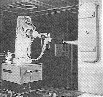
operator-programmer manually leads the robot’s end effector through the desired paint spray path. This defines the motion sequence and relative speed for the work cycle. During playback, the robot repeats the cycle to accomplish the paint spray operation. A spray painting robot is illustrated in Figure 11.5.
Among the many advantages of using robots for spray coating applications are the following:
1. Safety. The many safety hazards encountered when human operators perform the spray painting process are reduced.
2. Coating consistency. Once the program is established, the robot will deposit the paint or other coating with the same speed, pattern, and spray rate on every cycle.
3. Lower material usage. The robot’s repeatability and consistency reduce wasted paint. Savings in this category seem to range between 10 and 50%.
4. Less energy used. This results from reduced ventilation requirements since the human operator is removed from the actual process.
5. Greater productivity. The paint spraying robot can perform the operation faster than its human counterpart. It can also be used at this faster pace for three shifts per day.
11.6 Processing Operations
This is a miscellaneous category in which the robot is used to perform some manufacturing process other than welding or spray painting. Assembly and inspection operations are also excluded, and they are covered in the following sections.
Just as in welding and spray painting, the processing operation is performed by a specialized tool attached to the robot’s wrist as its end effector. The end effector is typically a powered spindle which holds and rotates a tool such as a drill. The robot would be used to bring the tool into contact with a stationary workpart during processing. In some applications which we will include within this category, the robot’s hand is used for gripping the workpart and bringing it into contact with a tool held in a fixed position. In the latter case, we begin to overlap with the types of machine loading applications covered earlier in this chapter.
Some of the processing operations which have been performed by industrial robots include drilling, riveting, grinding, polishing, deburring, wire brushing, and waterjet cutting. The following example will serve to illustrate the applications in this category.
Example 11.3
This example involves drilling and routing operations performed on aircraft components [5]. The components were sheet metal fuselage panels of various sizes and shapes for the F-16 fighter plane, manufactured by General Dynamics. A Cincinnati Milacron T3 robot was used in the workstation. A portion of the robotic work cell is pictured in Figure 11.6.
Figure 11.6 Cincinnati Milacron T3robot performing a processing operation. (Courtesy of Cincinnati Milacron, Inc.)
This application was developed under the U.S. Air Force ICAM (Integrated Computer-Aided Manufacturing) Program. The work cell has been producing fuselage panels since October, 1979, in a batch production mode. The workstation possesses the following operating features:
Integrated computer control of the workstation components.
Automatic part identification. A commercially available optical character reader is used to identify which workpart is to be processed next.
Mass data storage for part programs. After the workpart has been identified, the correct program for that part is selected from mass storage.
Automatic parts positioning. A weld positioner was used as the work cell parts positioner. It rotates the workpart into the proper registration for the robot to perform its drilling or routing process. While the robot is working on one side of the positioner, a human operator is unloading a finished part and loading a new part on the opposite side.
Automatic tool changing. A tool rack is used to store drills and routing tools for the operation. The appropriate tool for the task is selected automatically for the robot. It should be noted that this work cell was the object of considerable sponsored research and represents a more ambitious robot project than most of the applications included within this category on processing operations.
11.7 Assembly
Assembly operations are seen as an area with big potential for robot applications [8]. Batch-type assembly operations seem to offer the most promise for using robots. The reason for this is based on economics and the technological capabilities of the robot. For mass production assembly, the most economical method involves fixed automation, where the equipment is designed specifically to produce the particular product. A robot would probably be too slow for mass production, and one of the robot’s most important attributes, its programmability, would hardly be used. In batch assembly, there are variations in products and the demand for each product is significantly lower than in mass production. Consequently, the assembly line in batch manufacturing must be capable of dealing with these product variations and the line changeovers that are necessitated. What is basically required for batch production is a flexible assembly system. The term that some companies use for such a system is adaptable-programmable assembly system (APAS), and robot-type arms constitute an important component of these systems.
The APAS would be composed of both conventional material handling devices (conveyors, parts feeders, etc.) and robot arms, probably in an in-line arrangement as shown in Figure 11.7. The robot arms would be used for some parts handling duties, but its main function would be assembly. Robot assembly operations would typically require an extension of the robot’s material transfer capability. Many subassemblies consist of a stack of components on top of a base part. To put together the subassembly requires the placement of one part on top of
Figure 11.7 Possible arrangement of an adaptable-programmable assembly system using robots. (Reprinted with permission from Engelberger [4].)
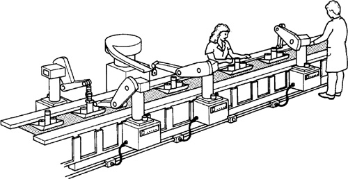
the base, then another part on top of that, and so forth. The robot is certainly capable of this sort of work cycle. Assembly tasks requiring a special skill or judgment, of which the robot is not capable, would be performed by human workers. Human assembly operators are shown on the APAS line in Figure 11.7.
The features of an industrial robot that make it suitable as a component of an APAS line are its programmability and its adaptability. Programmability is required so that a relatively complex motion cycle can be carried out during the assembly operation. Also, the APAS must be capable of storing multiple program sets to facilitate the differences in products assembled on the line. In this sense the system would be adaptable to changes in product style. Adaptability is also required in the sense that the assembly system would have to compensate for changes in the environment. These environmental variations include:
Variations in the position and orientation of assembly components
Out-of-tolerance and defective parts
The current state of completion of the subassembly
Detection of human beings or objects intruding on the robot’s work volume
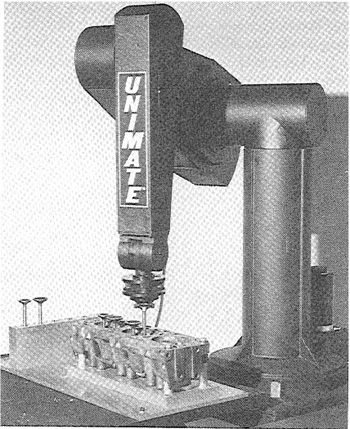
The PUMA (Programmable Universal Machine for Assembly) is a robot produced by Unimation, Inc. It was designed with assembly operations intended as one of its main functions. The PUMA is a relatively small robot (it requires a space about equal to that which a human operator would need) with a relatively low load-carrying capacity. One of the available PUMA models is pictured in Figure 11.8 performing a part insertion task.
Figure 11.8 Unimate PUMA 500 robot performing part insertion in an assembly operation. (Courtesy of Unimation, Inc.)
11.8 Inspection
Like assembly, inspection is a relatively new area for the application of industrial robots. Traditionally, the inspection function has been a very labor intensive activity. The activity is slow, tedious, and boring, and is usually performed by human beings on a sampling basis rather than by 100% inspection. With ever-increasing emphasis on quality in manufacturing, there is a trend toward automating the inspection process and toward the use of 100% inspection by machines instead of sampling inspection by human beings. An important role in this area of inspection automation will be played by industrial robots.
Robots equipped with mechanical probes, optical sensing capabilities, or other measuring devices can be programmed to perform dimensional checking and other forms of inspection operations. The following example will serve to illustrate a robotic inspection application.
Example 11.4
In this application, four Cincinnati Milacron T3 robots are used in an Automatic Body Checking (ABC) system at Ford Motor Company’s Wixom, Michigan, assembly plant [11].
The system performs dimensional inspections on Lincoln Continental and Mark VI automobile bodies. The ABC system is capable of inspecting five or six bodies per hour, whereas the previous manual methods could inspect only one or two bodies per shift.
The robots use electronic probes as their end effectors. With these probes, approximately 150 dimensional checks are made around the windshield, door, and back window openings. These checks are important because the openings receive mating parts (the windshield, doors, etc.) which must fit within fairly close tolerances.
Although the application resulted in a tremendous productivity improvement, the principal justification of a system such as this is product quality improvement.
REFERENCES
[1] BEHUNIAK, J. A., “Planning the Successful Robot Installation,” Robotics Today, Summer, 1981, pp. 36–37.
[2] CHRISTIAN, J. E., “Putting the Robot to Work,” Robotics Today, Spring, 1981, pp. 36–37.
[3] COUSINEAU, D. T., “Robots Are Easy, It’s Everything Else That’s Hard,” Robotics Today, Spring, 1981, pp. 28–35.
[4] ENGELBERGER, J. F., Robotics in Practice, AMACOM (American Management Associations), New York, 1980.
[5] GOLDEN, H. D., et al., “ICAM Robotics System for Aerospace Batch Manufacturing—Task A,” Technical Report AFWAL-TR-80-4042, Vol. I, Materials Laboratory, Air Force Wright Aeronautical Laboratories, Ohio, April, 1980.
[6] GROOVER, M. P., “Industrial Robots: A Primer on the Present Technology,” Industrial Engineering, November, 1980, pp. 54–61.
[7] HOLMES, J. G., AND RESNICK, B. J., “A Flexible Robot Arc Welding System,” Proceedings, Fourth National Industrial Robots Conference, Society of Manufacturing Engineers, November, 1979.
[8] JABLONOWSKI, J., “Robots That Assemble,” Special Report 739, American Machinist, November, 1981, pp. 175–190.
[9] KONDOLEON, A. S., “Assessing Cycle Times for Robot Assembly Systems,” Robotics Today, Summer, 1981, pp. 38–42.
[10] LOCKETT, J. H., “The Robotic Work Station in Small Batch Production,” Robotics Today, Winter, 1979–1980, pp. 17–19.
[11] MACRI, G. C., AND CALENGOR, C. S., “Robots Combine Speed and Accuracy in Dimensional Checks of Automotive Bodies,” Robotics Today, Summer, 1980, pp. 16–19.
[12] “Robot Teamwork Boosts Production and Lowers Cost at General Electric,” Robotics Today, Winter, 1981–82, pp. 33–34.
[13] STAUFFER, R. N., “Robogate and Unimates Team Up to Improve Quality and Efficiency,” Robotics Today, Summer, 1980, pp. 24–30.
[14] STAUFFER, R. N., “Industrial Robots, What They’re Doing, Where They’re Going,” Robotics Today, Fall, 1980, pp. 39–42.
[15] TANNER, W. R. (Ed.), Industrial Robots, Vol. I: Fundamentals1, Vol. II: Applications, Society of Manufacturing Engineers, Dearborn, Mich., 1979.
[16] TOEPPERWEIN, L. L., BLACKMAN, M. T., “ICAM Robotics Application Guide,” Technical Report AFWAL-TR-80-4042, Vol. II, Materials Laboratory, Air Force Wright Aeronautical Laboratories, Ohio April, 1980.
[17] UNIMATION INC., Unimate Industrial Robot System Planbook, Danbury, Conn.
[18] UNIMATION INC., Unimate Industrial Robot Welding Casebook, Danbury, Conn.
[19] WINSHIP, J. T., “Update on Industrial Robots,” American Machinist, January, 1979, pp. 121–124.