Chapter 3
Minicomputers, Microcomputers,
and Programmable Controllers
3.1 Introduction
During the mid-1960s, small computers began to appear on the market. To distinguish them from the larger mainframes of that period, they were called minicomputers. The appearance of these minicomputers reflected an ever-continuing trend of miniaturization in computer technology that has now reached the point where a CPU, together with a small main memory and input/output circuitry, can be contained on a single LSI (large-scale integrated) circuit chip several millimeters square. Such a chip, when combined with input and output devices, is called a microcomputer.
In this chapter we describe the minicomputer and microcomputer, which are frequently used in CAD/CAM applications. We also discuss the programmable controller, which is a related device often used in process control applications. Before considering the details of these three devices, we provide definitions and an overview of their applications.
Computers are generally considered to fall into three size categories, all of which are based on roughly the same architecture as that described in Chapter 2.
The three size categories are:
1. The large mainframe computer
2. The minicomputer
3. The microcomputer
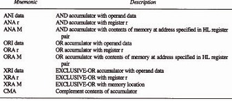
The large mainframe computer is distinguished by its cost, capacity, and function. The price of a new corporate general-purpose computer can run into millions of dollars. The main memory capacity is several orders of magnitude larger than the minicomputer, and the speed with which computations can be made is several times the speed of a minicomputer or microcomputer. The functions which are accomplished on a large mainframe computer can typically be classified into two categories, as described in Table 3.1. An example of a large mainframe computer was shown in Figure 2.2.
Minicomputers are smaller versions of the large mainframe computers. The trend toward miniaturization in computer technology provides two alternative approaches in the design of a computer. The first is to package greater computational power into the same physical size with each new computer generation. The second approach is to package the same computational power into a smaller size. The minicomputer manufacturers elected the second approach in developing their product lines. Traditionally, the cost of a minicomputer has ranged from less than a thousand dollars up to about $50,000. Minicomputers can be utilized for the same two general functions as a large mainframe computer (described in Table 3.1). However, the size of the jobs to be processed must be smaller to be within the capacity of the minicomputer. Smaller minicomputers often overlap with microcomputers in terms of the functions which they perform. These microcomputer/minicomputer functions are different from those performed by large mainframes. The characterisitics of typical minicomputer/microcomputer applications are described in Table 3.2.
A microcomputer uses a microprocessor as the basic central processing unit. The microprocessor consists of integrated circuits contained on LSI chips. The LSI
Table 3.1 Two Typical Applications Performed on Large Mainframe Computers and Large Minicomputers

Table 3.2 Typical Characteristics of Microcomputer/Minicomputer Applications
chips can be manufactured in large quantities very inexpensively. The microprocessor is capable of performing virtually all the functions of the conventional CPU (e.g., arithmetic—logic operations, or fetching data from memory). Accordingly, the microprocessor can be connected to a memory unit and the appropriate input/output device(s) to form a microcomputer. Typical characteristics of microcomputer applications are described in Table 3.2
The programmable controller (PC) was introduced in the late 1960s as a substitute for electromechanical relay logic systems. At that time relay control systems were typically used to regulate the operation of production equipment. The problems with electromechanical relays are their physical size and programming inflexibility. The programmable controller could perform the same functions as a relay logic system with greater flexibility and lower space requirements. The PC can be defined as a sequential logic device which generates output signals according to logic operations performed on input signals. The sequence of instructions that determines the inputs, outputs, and logical operations constitutes the program. The initial success of the programmable controller was due to its apparent similarity to relay control systems. Wiring charts called “ladder diagrams” have been used for many years to set up relay panels, and shop technical personnel are familiar with these diagrams for wiring and maintenance of the panels. Most PCs are programmed using the same type of ladder diagrams. Accordingly, shop people could easily adapt to the new control devices. In recent years, LSI technology in programmable controllers has reduced the differences between PCs and microcomputers/minicomputers. PCs can be interfaced with computers in production operations. The programmable controller is used to direct certain aspects of the operations while computers are used for other monitoring, control, and data processing functions.
The following three sections elaborate on the preceding discussion of minicomputers, microcomputers, and programmable controllers.
3.2 Minicomputers
A minicomputer is typically distinguished as a low-cost, general-purpose word-addressable computer with 4K to 32K of 8- to 16-bit words of main storage. Thirty-two-bit minicomputers are becoming more and more common. Two commercially available minicomputers are illustrated in Figures 3.1 and 3.2. Factors such as speed, ease of programming, and other operating characteristics are determined by the particular architecture of the minicomputer. The architecture of a minicomputer follows the general computer structure described in Section 2.1. The fundamental subunits are the memory, arithmetic and logic processor control unit, and input/output (I/O) unit.
The memory stores the instructions and data of both user and control programs. The arithmetic—logic processor receives data from memory and performs
Figure 3.1 A midrange-power minicomputer, the DEC PDP-11/24. Courtesy of Digital Equipment Corporation.)

Figure 3.2The more powerful VAX-11/730 model (background), a 32-bit minicomputer capable of supporting interactive graphics workstations. (Courtesy of Digital Equipment Corporation.)

operations on it as directed by the program instructions. The control unit regulates the flow of data in the system, fetches program instructions from memory, and decodes the instructions in instruction registers. Together, the arithmetic-logic processor and the control unit (along with registers and the interconnecting buses) are known as the CPU of the system. The input/output unit provides the interface to peripheral devices, transferring data to and from the external world.
Minicomputers are sometimes designed with memory as a device external to the system (like a peripheral), and communication is established over an I/O bus. The resulting single-bus architecture is more efficient because the CPU is independent of memory timing. This allows for high-speed memory to be added to the system at a later date without extensive CPU modification. The single-bus structure also permits memory devices of different speeds to be used within the same system.
Minicomputer instructions
The basic minicomputer instruction consists of two parts: an operation code and an operand. The operation code specifies the function to be performed (arithmetic operation, data transfer, etc). This function is executed when its operation code is properly decoded by the CPU control logic. The operation is performed on data that are contained in memory. The operand typically consists of an address and an addressing mode. The address specifies the memory location of the data. The addressing mode refers to the method by which the data are accessed. The data might be accessed directly by going to the address specified in the instruction, or it could be accessed by any of several other schemes.
The instruction is carried out during the minicomputer instruction cycle. This consists of a series of events which can be grouped into two phases: fetch and execute. During the fetch phase, the control logic fetches the address of the instruction from the program counter. This address is decoded by the decoder circuitry. The instruction is brought from this address in memory and loaded into the instruction register, where it is decoded.
During the execution phase of the cycle, the particular operation (e.g., addition, subtraction, comparison, or other) defined by the contents of the instruction register is carried out. Each instruction has a unique sequence of steps associated with its execution.
Most of the processing that occurs in the minicomputer during program execution takes place in registers. Several of the various types of registers were described in Section 2.2. The number and type of registers in the computer architecture determine its performance. Generally, as the number of registers in a minicomputer is increased, the required program size and the execution time decrease. Thus an indication of computing power in a minicomputer is its number of registers.
A minicomputer is provided with the capability to perform a variety of operations and functions, such as data transfers, arithmetic operations, and logic functions. These operations and functions are known as the instruction set. Most minicomputer instruction sets consist of less than 200 instructions. However, only a portion of these are likely to be used in a typical program.
The instructions can be classified as memory or nonmemory. Memory instructions are used to transfer data to and from memory locations. Nonmemory instructions carry out the other functions of the computer. The nonmemory instructions can be divided into two categories:
Arithmetic and logic functions
Input/output instructions
The arithmetic instructions include functions such as addition, subtraction, multiplication, and comparisons. Logical functions include Boolean operations such as AND, OR, and EXCLUSIVE OR.
Input functions are concerned with the transfer of data between main storage and peripheral devices. The factors that determine the I/O capability of a minicomputer are its I/O transfer speed, the number and types of I/O software schemes available, and the priority control structure, which permits external devices to interrupt the execution of the CPU.
Input/output functions are either controlled or interrupt driven. Controlled I/O functions are usually accomplished by means of the system programming. In this case, data are transferred to and from peripheral devices through an I/O bus.
The I/O bus is equipped with circuitry that can decode the address of a specific peripheral in order to effect the transfer of data to it. In some computers, the device address is given directly, and the circuitry transfers the data to that device during a clocked time period associated with that specific device. This method of transfer is called time multiplexing. I/O transfer rates vary. The rate is limited by the fact that the CPU must constantly poll the peripheral channels to determine which devices are requesting service.
Interrupt-driven input/output occurs when the peripheral device is capable of stopping the execution of the current programs in the CPU and transferring program control to special service subroutines. These subroutines, when called, must save the contents of the working registers, the status register, and the program counter, so that when control is returned to the main program, no changes will have taken place and execution of the previous program can continue.
Microprogramming
In the conventional minicomputer, the architecture consists of memory, arithmetic-logic processor, a control unit, and an I/O section. A microprogrammed minicomputer differs from the conventional machine in the sense that the control unit, instead of being hard-wired logic, is a stored-program device. The control unit consists of two functional parts, the control decode and the control store. The control decode operates all elements of the computer system, including main storage and high-speed control store. The control store contains microprograms called firmware. The firmware corresponds to conventional computer sequences (software).
Microprogramming increases the speed with which the minicomputer can operate. For certain operations, a microprogrammed minicomputer can perform at considerably higher speeds than a conventional minicomputer. When a large microinstruction set is available, the machine can be optimized to perform a broad variety of high-speed tasks.
3.3 Microcomputers
Microcomputers are generally smaller than minicomputers. As indicated in the introduction, the CPU, I/O circuitry, and a small amount of memory are all implemented by means of integrated circuits contained on a very small silicon base, called an LSI chip. Despite the small size of its circuitry, the microcomputer is capable of performing all the regular functions of a traditional computer. Because of its small size, the cost of a microcomputer is potentially much lower than the cost of a minicomputer. The cost of the microprocessor (the LSI circuit on a chip used as the CPU) can be as low as a few dollars when produced in large quantities. Because of its low cost, as well as limitations on its capabilities, microcomputers are typically used for functions different from those of a traditional computer. The
Figure 3.3 A microcomputer, the DEC MICRO/PDP-11. (Courtesy of Digital Equipment Corporation.)

characteristics of these microcomputer functions are described in Table 3.2 Figure 3.3 illustrates a commercially available microcomputer.
Microcomputer instructions
The microcomputer instruction cycle operates in much the same manner as the minicomputer instruction cycle. It consists of the fetch and execute phases, which are each composed of smaller steps.
The instruction set for a microcomputer consists of the instructions for operations which can be accomplished by the CPU. Different microcomputers possess varying capabilities and, accordingly, there are differences in their instruction sets. The types of instructions generally provided include:
1. Data transfer and input/output instructions
2. Arithmetic operations
3. Logical operations
4. Branching instructions
The following paragraphs describe these four categories of microcomputer instructions.
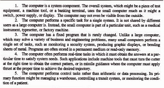
Table 3.3 Data Transfer and Input/Output Instructions for the Intel 8085A
DATA TRANSFER AND INPUT/OUTPUT INSTRUCTIONS. This type of instruction is concerned with the transfer of data between a microprocessor register and another component, such as memory, an I/O device, or another register. Each instruction specifies a source register and a destination register. If the destination register is part of the CPU, this is usually implied in the instruction. This type of register is called an internal register. External registers, on the other hand, must be explicitly named in the instruction. Table 3.3 presents a listing of instructions in this category for the Intel 8085A microprocessor.
ARITHMETIC OPERATIONS. Simple arithmetic operations (such as addition and subtraction), as well as more complex operations (multiplication, division, etc.), can be executed by means of the appropriate instructions in this category. Instructions for binary addition are always provided in the microprocessor’s instruction set. Subtraction is usually provided also. Multiplication and division can be accomplished either directly in hardware by means of special hardware circuits or by software in the form of subroutines. These more complex operations are not typically included within the instruction sets for 8-bit microprocessors. Microprocessors with 16-bit and greater capacity would usually include multiplication and division instructions. Table 3.4 presents some typical basic instructions for executing arithmetic operations.
Table 3.4 Microprocessor Instructions for Arithmetic Operations

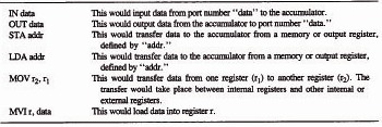
Table 3.5 Microprocessor Instructions for Logical Operations (Intel 8085A Microprocessor)
LOGICAL Operations. Most microprocessors include instructions for carrying out the logical operations AND, OR, NOT, and EXCLUSIVE-OR. As an illustration, Intel Corporation’s 8085A microprocessor includes the instructions presented in Table 3.5 to accomplish logical manipulations of data.
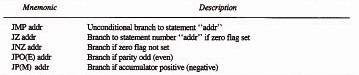
BRANCHING OPERATIONS. A branch instruction causes program control to be transferred from the current value of the program counter to another, nonconsecutive instruction. In the Intel 8085A, branching is implemented through the “jump” instruction. Branching operations make possible the use of program loops, in which a series of program instructions can be executed repeatedly.
Branching can be made conditional on a set of circumstances, or it can be made unconditional. In the unconditional jump instruction, the address specified in the instruction is loaded into the program counter, and control of execution is passed there. Conditional branches can be performed such that if the given condition is true, the operation is carried out. Otherwise, it is ignored, and program execution proceeds sequentially. Several branching instructions are given in Table 3.6.
Table 3.6 Branching Instructions (Intel 8085A)
Example 3.1
We will use two examples to illustrate the use of these instructions. The first problem is to write a program in assembly language which will simulate a NOR gate. (A NOR gate is a hardware device with two inputs and one output which operates as follows: If both inputs are zeros, the output is one; otherwise, the output is zero.) In other words, we want to use software to duplicate the operation of a hardware device. The program, based on instructions from Tables 3.3, 3.4, and 3.5, is shown below with explanations at the right.
IN dataa Input the first data (dataa)
MOV B, A Move first data to register B
IN datab Input the second data (datab)
ORA B Use “or” on first and second data (dataa and datab)
CMA Complement the accumulator
Example 3.2
The second example shows how a microprocessor might be programmed to operate in an industrial situation. Suppose that an incoming conveyor has three limit switches vertically positioned so that it will sense three different sizes of boxes. Based on the input signal received from the limit switches, the microprocessor program should output a corresponding signal to a sorter so that each size of box is diverted to a separate conveyor. The input should be the first 3 bits of address data, with all other bits grounded to zero. We will assume that an IN command will accomplish the input of the data from the limit switches. The input data corresponding to three limit switches are:
0000 0001 One limit switch activated (corresponding to smallest box)
0000 0011 Two limit switches activated (corresponding to middle-size box)
0000 0111 Three limit switches activated (corresponding to largest box)
The program, using statements from Tables 3.3 through 3.6, would be as follows:
IN data Input data to accumulator
SUIOOOO 0001 Subtract first bit
JZONE Test for one limit switch
SUI0000 0010 Subtract second bit
JZTWO Test for two limit switches
MVIA, 0000 0100 Signal to divert largest box to its conveyor stored in accumulator
IMPEND Unconditional jump to statement END
ONE: MVIA, 0000 0001 Signal to divert smallest box to its conveyor stored in accumulator
JMPEND Unconditional jump to statement END
TWO: MVIA, 0000 0010 Signal to divert medium-size box to its conveyor stored in accumulator
END: OUT data Output the signal stored in the accumulator to the system
3.4 Programmable Controllers
The National Electrical Manufacturers Association defines a programmable controller (PC) in the following terms as NEMA Standard ICS3-1978, Part ICS3-304(5):
A digitally operating electronic apparatus which uses a programmable memory for the internal storage of instructions for implementing specific functions such as logic, sequencing, timing, counting, and arithmetic to control, through digital or analog input/output modules, various types of machines or processes. A digital computer which is used to perform the functions of a programmable controller is considered to be within this scope. Excluded are drum and similar mechanical type sequencing controllers.
Programmable controllers were first introduced around 1969 and are available today in a wide variety of styles from a variety of manufacturers. One model is pictured in Figure 3.4. PCs have been used in a wide variety of industrial applications, including transfer machines, flow line conveyor systems, injection molding, grinding, welding, cement processing, food processing, energy management, and control of production testing equipment.
Figure 3.4 A series of programmable controller models with CRT terminal in foreground for programming. (Courtesy of General Electric Company.)

Components of a PC
The basic components of any programmable controller are the following:
Input/output interfaces
Processor
Memory
Programming device
Power supply
These components will be contained in suitable housings and cabinets to permit them to withstand the shop environment. The configuration of the PC system is illustrated in Figure 3.5.
The programmable controller is designed to be connected to industrial equipment. This connection is accomplished by means of the input/output interface. The input interface is designed to receive process and machine signals and convert them into an acceptable form for the PC. The output interface converts PC control signals into a form which can be used by the process equipment. The input interfaces are separate from the output interfaces, and both types are designed to be modular for flexibility. One I/O module might be designed for up to 16 circuits. The external signals which must be interfaced with the PC through the I/O modules might include [5]:
AC voltage, various levels
DC voltage
BCD (binary-coded decimal) inputs and outputs
Pulse data
Low-level analog signals such as thermocouple millivolt signals
The internal operation of a programmable controller would typically be based on low-voltage dc (e.g., 5 V dc).
Figure 3.5 Typical programmable controller configuration.

The processor is the central component of the PC and is sometimes referred to as the central processing unit (CPU). It executes the various logic functions, performs operations on inputs, and determines the appropriate outputs. As microprocessor technology has developed, these devices have been incorporated in the PC processor design to increase its mathematical and decision-making capabilities.
The PC memory is used to store the program which specifies the logic of the input/output processing. Memory for a programmable controller is specified the same way as for a digital computer (e.g., 1K equals 1024 bits of storage). Memory capacities of commercial PCs range from less than 1K up to more than 48K.
The program is loaded into the PC memory by means of a programming device. Either of two types of programming devices can be used for this purpose. The first is the CRT terminal as pictured in Figure 3.4. The CRT permits the programmer to use either a relay ladder diagram or other programming language to input the control logic into memory. We will consider programming of the PC in the following subsection. The second type of programming device is a small, manual keyboard device. With this device, the control logic and other data are entered by means of special function buttons and thumbwheels. Manual programming devices are less expensive and more portable, but the CRT is more convenient for programming.
The power supply drives the PC and serves as a source of power for the output signals. It is also used to help protect the PC against noise in the electrical power lines.
Programming the PC
One of the attractive features of a PC is considered to be its ease of programming. Shop personnel who are familiar with relay ladder diagrams are not required to learn a totally new language in order to use the programmable controller. Various PC manufacturers offer different language formats but there are three basic types of PC programming languages:
Relay ladder diagrams
Boolean-based languages
Mnemonic languages similar to computer assembly languages
The three types are illustrated in Figure 3.6.
Relay ladder diagrams are currently the most popular type, owing to the fact that electricians, control engineers, and maintenance personnel are familiar with them. As shown in Figure 3.6, the ladder diagrams consist of symbols representing normally open and closed contacts and other components to control electrical equipment.
Boolean-based languages make use of logic statements to establish relationships among PC inputs and outputs. These Boolean statements can include logical
Figure 3.6 Three basic types of PC programming languages. The most popular is the relay ladder diagram illustrated in the top two sections of the figure. (Reprinted from Jannotta [5].)

“AND” (represented by a dot), “OR” (+), and equal (=). These symbols are shown in the Boolean statement of Figure 3.6.
The third type of PC language is quite similar to computer assembly language. The language would include statements such as LOAD, AND, OR, and STORE, as illustrated in the figure. The address attached to the statement would be used to identify a particular input/output signal. Programming the PC by means of one of these mnemonic languages often requires the assistance of a computer programmer since plant personnel are usually unfamiliar with them. However, use of these computer-type languages is expected to increase in the future as knowledge about computers becomes more widespread.
Programmable controller functions
Some of the basic functions performed by a programmable controller include the following:
1.Control relay functions. These functions involve the generation of an output signal from one or more inputs according to a particular logic rule contained in the PC memory. The example shown in Figure 3.6 is illustrative of the kind of logic rules used in control relay functions.
2.Timing functions. Most programmable controllers allow the programming of timing functions. This might be used to generate an output signal a specified delay time after an input signal has been received. Another example would be to maintain an output signal for a certain length of time and then shut off.
3.Counting functions. Counting functions are similar to timing functions. The counter adds up the number of input contact closures and generates a programmed output when the sum reaches a certain count. The counter would then be reset to repeat the cycle.
4. Arithmetic functions. As the use of programmable controllers in industry has grown, PCs have been equipped with more features and capabilities. In addition to the basic relay logic functions, timers, and counters, some PCs offer mathematical functions such as addition, subtraction, and in certain cases, multiplication and division. Hence it is possible to use the controller for more sophisticated processes where complex calculations are required.
5.Analog control functions. Analog control devices are used to accomplish proportional, integral, and derivative control functions. (An explanation of these control functions is provided in Section 13.5 of Ref. [2].) The capability to perform these control functions is available on some PCs, which permits it to be utilized to regulate analog devices directly.
The first three functions are common features on programmable controllers. Arithmetic and analog control functions are available on only the more powerful PCs.
Advantages of the programmable controller
There are many advantages of the programmable controller compared to the use of conventional relay controls. Among these are the following:
Programming the PC is generally much easier than wiring the conventional relay control panel.
The PC can be reprogrammed. Conventional controls must be rewired to alter the control logic, and they are often scrapped instead because of the time and expense involved in rewiring.
Programmable controllers often require less floor space than do conventional relay controls.
Maintenance of the PC is easier, and reliability is better.
The programmable controller can be interfaced with plant computer systems more easily than relays can.
In recent years, the use of microprocessors has increased the capabilities of PCs and has tended to reduce the differences between programmable controllers and minicomputers/microcomputers. Let us examine some of the differences.
Computers versus programmable controllers
The difference between programmable controllers and computers is more a difference in application than a difference in technology. The technologies have, in fact, become quite similar. A programmable controller can be thought of as a specialized computer. The intended applications of the PC have caused this specialization.
One difference between the PC and a computer is that the programmable controller is designed to be interfaced with industrial processes. The inputs and outputs of the PC can be wired directly to production equipment in the plant through the I/O modules. With computers, special arrangements have to be made to link up with the process, as we shall discuss in Chapter 17.
Another difference, related to the first, is that programmable controllers are intended to be placed in an industrial plant environment. The typical features of this environment include vibration, electrical noise, humidity, and a wide range of temperatures. The PC is designed to function in this type of environment. Its operating specifications typically call for a temperature range from 0 to 60°C (32 to 140°F) and a range of relative humidity from 0 to 95% [5].
Finally, a third important difference between a PC and a computer is in the programming. The PC uses a programming language (the relay ladder diagram) which is familiar to shop personnel. Similarly, the maintenance of the PC can also be accomplished by plant electricians since the system is modular and diagnostics are therefore made easier.
References
[1] DELTANO, D., “Programming Your PC,” Instruments and Control Systems, July, 1980, pp. 37–40.
[2] GROOVER, M. P., Automation, Production Systems, and Computer-Aided Manufacturing, Prentice-Hall, Inc., Englewood Cliffs, N.J., 1980, Chapter 11.
[3] HICKEY, J., “PCs: Reasons Why They’re Used,” Instruments and Control Systems, April, 1980, pp. 59–61.
[4] HICKEY, J., “PC Application Ideas,” Instruments and Control System, September, 1980, pp. 67–70, and October 1980, pp. 55–59.
[5] JANNOTTA, K. L., “What Is a PC?” Instruments and Control Systems, February, 1980, pp. 21–25.
[6] LEVENTHAL, L. A., Introduction to Microprocessors: Software, Hardware, Programming, Prentice-Hall, Inc., Englewood Cliffs, N.J., 1978.
[7] SHORT, K. L., Microprocessors and Programmed Logic, Prentice-Hall, Inc., Englewood Cliffs, N.J., 1981.
Problems
The following programming problems are to be answered using only the instructions found in Tables 3.3 through 3.6. It is appropriate to assume that no values overflow the registers during the computations and that no negative numbers are used.
3.1. Write an assembly language program that will simulate a NAND gate. (A NAND gate is a device with two inputs and one output which operates as follows: If both inputs are one, the output is zero; otherwise, the output is one.)
3.2. Write a program to perform a multiplication operation using the contents of registers B and C as inputs. Disregard computational speed.
3.3. Write a program to perform a division operation using the contents of the accumulator to divide by the contents of register B. Assume that there will be no remainder and disregard computational speed. Also, assume that all other registers are zero.
3.4. Write a program that will perform the power operation. Disregard the issue of computational speed. (Hint. Use the program developed by problem 3.2 as a starting point.)
3.5. A heat sensor continually measures the temperature of the space shuttle. If the temperature is between 50 and 64°F inclusive, a heater is to be turned on. If the temperature is between 65 and 75°F inclusive, all units are turned off. If the temperature is between 76 and 100°F inclusive, an air conditioner is turned on. If it is greater than 100°F or less than 50°F, a status check is made of the shuttle’s systems. If something is malfunctioning, an alarm is turned on. If nothing is found wrong during the status check, the temperature is checked again. If the temperature is still out of range, the alarm is sounded even though all systems seem to be functioning properly. Write a program that will accomplish the series of logical operations described. (Hint: Refer back to Example 3.2, a similar problem.)
3.6. Is the situation described in Example 3.2 more appropriate for a microprocessor or a programmable controller? List the relative advantages and disadvantages to support your answer.