Chapter 2
Computer Technology
2.1 Introduction
The central and essential ingredient of CAD/CAM is the digital computer. Its inherent speed and storage capacity have made it possible to achieve the advances in image processing, real-time process control, and a multitude of other important functions that are simply too complex and time consuming to perform manually. To understand CAD/CAM, it is important to be familiar with the concepts and technology of the digital computer. In this first part of the book, we focus on computers as a foundation for computer-aided design and manufacturing.
The modern digital computer is an electronic machine that can perform mathematical and logical calculations and data processing functions in accordance with a predetermined program of instructions. The computer itself is referred to as hardware, whereas the various programs are referred to as software.
There are three basic hardware components of a general-purpose digital computer:
1. Central processing unit (CPU)
2. Memory
3. Input/output (I/O) section
Figure 2.1 Basic hardware structure of a digital computer.
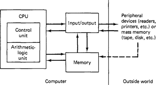
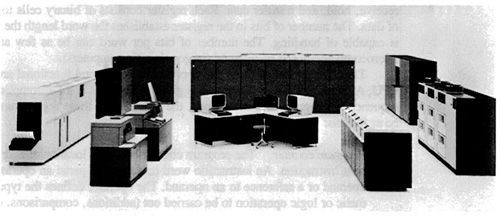
The relationship of these three components is illustrated in Figure 2.1. The central processing unit is often considered to consist of two subsections: a control unit and an arithmetic-logic unit (ALU). The control unit coordinates the operations of all the other components. It controls the input and output of information between the computer and the outside world through the I/O section, synchronizes the transfer of signals between the various sections of the computer, and commands the other sections in the performance of their functions. The arithmetic-logic unit carries out the arithmetic and logic manipulations of data. It adds, subtracts, multiplies, divides, and compares numbers according to programmed instructions. The memory of the computer is the storage unit. The data stored in this section are arranged in the form of words which can be conveniently transferred to the ALU or I/O section for processing. Finally, the input/output provides the means for the computer to communicate with the external world. This communication is accomplished through peripheral equipment such as readers, printers, and process interface devices. The computer may also be connected to external storage units (e.g., tapes, disks, etc.) through the I/O section of the computer. Figure 2.2 shows a modern large computer with associated peripheral equipment including storage units, card reader, and printer.
The software consists of the programs and instructions stored in memory and in external storage units. It is the software that assigns to the computer the various functions which the user desires the system to accomplish. The usefulness of the computer lies in its ability to execute the instructions quickly and accurately. Because the contents of the computer’s memory can be easily changed, and therefore different programs can be placed into memory, the digital computer can be used for a wide variety of applications.
Regardless of the application, the computer executes the program through its ability to manipulate data and numbers in their most elementary form. The data and numbers are represented in the computer by electrical signals which can take one of two alternative states. This form of representation is called the binary system. The more familiar decimal number system and a whole host of software
Figure 2.2 A modern large mainframe computer and associated peripheral hardware. The computer is the IBM 3033 processor. (Courtesy of IBM Corporation.)
languages can utilize the binary system to permit communication between computers and human beings.
2.2 Central Processing Unit (CPU)
The central processing unit (CPU) regulates the operation of all system components and performs the arithmetic and logical operations on the data. To accomplish these functions, the CPU consists of two operating units:
1. Control unit
2. Arithmetic-logic unit (ALU)
The control unit coordinates the various operations specified by the program instructions. These operations include receiving data which enter the computer and deciding how and when the data should be processed. The control unit directs the operation of the arithmetic-logic unit. It sends data to the ALU and tells the ALU what functions to perform on the data and where to store the results. The capability of the control unit to accomplish these operations is provided by a set of instructions called an executive program which is stored in memory.
The arithmetic and logic unit performs operations such as addition, subtractions, and comparisons. These operations are carried out on data in binary form. The logic section can also be used to alter the sequence in which instructions are executed when certain conditions are indicated and to perform other functions, such as editing and masking data for arithmetic operations.
Both the control unit and the arithmetic-logic unit perform their functions by utilizing registers. Computer registers are small memory devices that can receive, hold, and transfer data. Each register consists of binary cells to hold bits of data. The number of bits in the register establishes the word length the computer is capable of handling. The number of bits per word can be as few as 4 (early microcomputers) or as many as 64 (large scientific computers).
The arrangement of these registers constitutes several functional areas of the CPU. A representative configuration is given in Figure 2.3. To accomplish a given sequence of programmed instructions, the functions of these register units would be as follows:
Program counter. The program counter holds the location or address of the next instruction. An instruction word contains two parts: an operator and an operand or a reference to an operand. The operator defines the type of arithmetic or logic operation to be carried out (additions, comparisons, etc.). The operand usually specifies the data on which the operation is to be performed. The CPU sequences the instructions to be performed by fetching words from memory according to the contents of the program counter. After each word is obtained, the program counter is incremented to go on to the next instruction word.
Memory address register. The location of data contained in the computer’s memory units must be identified for an instruction, and this is the function of the memory address register. This unit is used to hold the address of data
Figure 2.3 Typical arrangement of registers in the computer’s CPU. (From Lance A. Levanthal, Introduction to Microprocessors: Software, Hardware, Programming, ©1978, p. 128. Reprinted by permission of Prentice-Hall, Inc., Englewood Cliffs, N.J.)

held in memory. A computer may have more than a single memory address register.
Instruction register. The instruction register is used to hold the instruction for decoding. Decoding refers to the interpretation of the coded instruction word so that the desired operation is carried out by the CPU.
Accumulator. An accumulator is a temporary storage register used during an arithmetic or logic operation. For example, in adding two numbers, the accumulator would be used to store the first number while the second number was fetched. The second number would then be added to the first. The sum, still contained in the accumulator, would then be operated on or transferred to temporary storage, according to the next instruction in the program.
Status register. Status registers are used to indicate the internal condition of the CPU. A status register is a 1-bit register (often called a flag). Flags are used to identify such conditions as logical decision outcomes, overflows (where the result of an arithmetic operation exceeds the word capacity), and interrupt conditions (used in process control).
Arithmetic-logic unit (ALU). The ALU provides the circuitry required to perform the various calculations and manipulations of data. A typical configuration of the arithmetic-logic unit is illustrated in Figure 2.4. The unit has two inputs for data, inputs for defining the function to be performed, data outputs, and status outputs used to set the status registers or flags (described above).
The arithmetic-logic unit can be a simple adder, or its circuitry can be more complex for performing other calculations, such as multiplication and division. ALUs with simpler circuits are capable of being programmed to perform these more complicated operations, but more computing time is required. The more complex arithmetic-logic units are faster, but these units are more costly. Referring to Figure 2.4, the two inputs, A and B, enter the ALU and the logical or mathematical operation is performed as defined by the function input. Among the
Figure 2.4
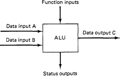
possible functions are addition, subtraction, increment by 1, decrement by 1, and multiplication. The ALU places the result of the operation on A and B in the output, C, for transfer to the accumulator.
2.3 Types Of Memory
The memory section consists of binary storage units which are organized into bytes (there are typically 8 bits per byte). A byte is a convenient size for the computer to handle. Computer words can typically be 4, 8, 12, 16, 32, or 64 bits long. Each word has an address in the memory. The CPU calls words from memory by referring to the word address. The time required to find the correct address and fetch the contents of that memory location is called the access time. Access time is an important factor in determining the speed of the computer. Access times range from 10-7s (100 ns) to several microseconds.
The memory section stores all the instructions and data of a program. Thus the CPU must transfer these instructions and data (in the form of words) to and from the memory throughout the execution of the program.
Today, the technology and conceptual framework of computer storage represents a rapidly changing field. The type of memory is a very important consideration in the design of the entire computer system. We will adopt a very conventional organization of this topic by dividing computer memories into two basic categories:
1. Main memory (primary storage)
2. Auxiliary memory (secondary storage)
In present-day computer systems, there often exist a greater number of hierarchical levels of computer memory. The reader interested in this topic might want to refer to either of two books in our list at the end of the chapter [7, 14].
Main memory (primary storage)
The main memory or primary storage are terms which designate storage areas that are physically a part of the computer and connected directly to the CPU. It includes the working registers and memory devices closely configured to the CPU. Primary storage can be divided into three main categories:
1. Main data storage, such as magnetic core or solid-state memory. This storage is characterized by its close proximity to the CPU, fast access rate, relatively low storage capacity, and very high cost compared to other forms of memory.
2. Control storage, which commonly contains the microprograms that assist the CPU circuitry in performing its functions.
Table 2.1 Types of Computer Storage Technology for Main Data Storage
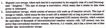
3. Local storage, the high-speed working registers used in the arithmetic and logical operations.
Some of the principal types of storage technology commonly used in computer systems to accomplish the main data storage (category 1) are listed in Table 2.1.
Auxiliary memory (secondary storage)
Programs and data files are not generally kept in primary storage but are stored on large-capacity auxiliary devices and loaded into main memory as required. Main storage is very expensive, and has a rather limited capacity (the capacity is limited somewhat by its high cost). Also, some operations require more data than can be held in main storage at one time. As an example, an airline reservation system may use a file containing information about each scheduled flight (available seating, passenger information, arrival and departure times, ticket prices, etc.). The set of characteristics for each flight is called a record, and the set of all the flight records is called a file. It would be inefficient from a processing standpoint to tie up main memory with a file as large as this, especially when only one flight record is needed at any given time. To eliminate this problem, the entire file is stored on an auxiliary device, and individual records are accessed as needed by the reservation program. These auxiliary devices constitute the secondary storage and are physically external to the computer, which means that the programs and data files are not directly available to the CPU. There are two basic types of secondary storage:
1. Sequential access storage. A sequential access storage unit is distinguished by the fact that to read one particular record in the file, all records preceding it must also be read.
2. Direct access storage. With this storage method, individual records can be located and read immediately without reading any other records.
Because of its method of operation, the sequential storage method has a substantially lower access rate than that of direct access storage. On the other hand, the cost per bit of data stored is higher for the direct access method, and its technology is more complicated. These factors tend to define the applications of the two storage types. Sequential access storage is suitable for applications that do not require a high level of file activity. Direct access storage is best suited to files where a high level of activity is involved. The airline reservation system described earlier would be an appropriate application for direct access storage.
Table 2.2 presents a list of some of the hardware devices and storage technology used in computer systems. Most of this technology refers to secondary storage.
2.4 Input/Output
The purpose of the input/output section of the computer is to provide communication with the variety of peripheral devices used with the computer system. As the name implies, there are two inverse functions involved. First, programs and data are read into the computer. The I/O section must interpret the incoming signals and hold them temporarily until they are placed in main memory or into the CPU. Second, the results of the calculations and data processing operations must be transmitted to the appropriate peripheral equipment.
In the conventional applications of the computer (e.g., scientific and engineering calculations, business data processing, manufacturing support functions), the computer must communicate with people via the peripheral devices. In Table 2.3 we present a list of some of the traditional and modern peripheral devices used to communicate with the computer for these conventional applications.
In Chapters 4, 5, and 6 our attention will be directed to the topic of computer-aided design. The operation of a CAD system involves a great deal of interactive communication between the human designer and the computer system. The specialized input/output section and associated peripheral equipment required in computer-aided design will be discussed in those chapters (Chapter 5 in particular).
2.5 Data Representation
Computer systems depend on the capability to represent and manipulate symbols. When we communicate with the computer and its peripheral equipment, the data and programming instructions must be reduced to a set of symbols which can be interpreted by the system. The symbols used by the computer are based on electrical signals that can take one of two states. The smallest unit of data is the bit. It has two possible values, on or off (1 or 0). The bits can be arranged into groups and, depending on the sequential bit values, the group can be used to represent a more sophisticated symbol such as a number or alphabetic character. By arranging these numbers and letters into groups, information and programming instructions can be communicated to and from the computer.
The purpose of the peripheral devices described in Table 2.3 is to accomplish
Table 2.2 Hardware Devices Used for Computer Storage Technology
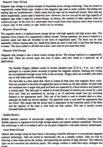
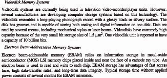
Table 2.3 Common Peripheral Devices Used for Computer Input/Output
the conversion process between the higher-level characters (numbers and letters) and the basic units of data used by the computer (the bit).
The binary number system
The bit, or binary digit, is the basic unit of data which can be interpreted by the digital computer. It is easily adaptable to the binary number system because there are only two possible conditions which can take on the values of 0 or 1. The meaning of successive digits in the binary system is based on the number 2 raised to successive powers. The first digit is 20, the second is 21, the third is 22, and so forth. The two numbers, 0 or 1, in successive bit positions indicate either the absence or presence of the value. Table 2.4 shows how the binary number system can be used to represent numbers in the more familiar decimal system.
The conversion from binary to decimal systems makes use of the following type of computation. We will illustrate the conversion for the decimal number 5:
1 X 20 + 0 X 21 + 1 X 22 + 0 X 23
= 1 X 1 + 0 X 2 + 1 X 4 + 0 X 8 = 5
Table 2.4 Binary and Decimal Number System Equivalence
A minimum of four digits are required in the binary system to represent any single-digit number in the decimal system, as indicated in Table 2.4. By using more than four binary digits, higher-valued decimal numbers or other high-level data can be represented.
An alternative way to represent decimal numbers larger than nine involves separate coding of each digit, using four binary digits for each decimal digit. This coding system is known as binary-coded decimal (BCD). The binary-coded decimal system is explained in Table 2.5 together with two other common coding schemes.
Table 2.5 Common Binary Coding Schemes

2.6 Computer Programming Languages
The preceding section demonstrated how the binary number system could be used to represent any decimal number, alphabetic letter, or other common symbol. Data and instructions are communicated to the computer in the form of binary words. In executing a program, the computer interprets the configuration of bits as an instruction to perform electronic operations such as add, subtract, load into memory, and so forth. The sequence of these binary-coded instructions define the set of calculations and data manipulations by which the computer executes the program.
The binary-coded instructions that computers can understand are called machine language. Unfortunately, binary-coded instructions and data are very difficult for human programmers to read or write. Also, different machines use different machine languages. To facilitate the task of computer programming, higher-level languages are available which can be learned with relative ease by human beings. In all there are three levels of computer programming languages:
1. Machine language
2. Assembly language
3. Procedure-oriented (high-level) languages
Machine and assembly languages
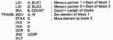
The language used by the computer is called machine language. It is written in binary, with each instruction containing an operation code and an operand. The operand might be a memory address, a device address, or data. In machine language programming, storage locations are designated for the program and data, and these are used throughout the program to refer to specific data or program steps. In addition, the programmer must be familiar with the specific computer system since machine language instructions are different for each computer. Programming in machine language is tedious, complicated, and time consuming. To alleviate the difficulties in writing programs in binary, symbolic languages have been developed which substitute an English-like mnemonics for each binary instruction. Mnemonics are easier to remember than binary, so they help speed up the programming process. A language consisting of mnemonic instructions is called an assembly language. Figures 2.5 and 2.6 illustrate the difference between machine language and assembly language.
Assembly languages are considered to be low-level languages. The programmer must be very knowledgeable about the computer and equipment being programmed. Low-level languages are the most efficient in terms of fast execution on the computer, but there are obvious difficulties for the programmer in writing large programs for various applications using different computers. We consider programming with assembly language in Chapter 3 in our discussion of microcomputers and microprocessors.
Figure 2.5.
Figure 2.6. Portion of an assembly language program. (From Lance A. Leventhal, Introduction to Microprocessors: Software, Hardware, Programming, ©1978, p. 129. Reprinted by permission of Prentice-Hall, Inc., Englewood Cliffs, N.J.)
Assembly language programs must be converted into machine language before the computer can execute them. The conversion is carried out by a program called an assembler. The assembler takes the assembly language program, performs the necessary conversions, and produces two new programs: the machine language version and an assembly listing. The assembly listing shows the mnemonic instructions and their associated machine language equivalents, and any errors the original assembly language program may have contained.
High-level language
Assembly languages are machine oriented. High-level languages, by contrast, are procedure oriented. They are to a large extent independent of the computer on which they are used. This means that a program written on one computer can be run on a different computer without significant modifications to the program.
High-level languages consist of English-like statements and traditional mathematical symbols. Each high-level statement is equivalent to many instructions
Figure 2.7 Portion of FORTRAN program. (From Lance A. Levanthal, Introduction to Microprocessors: Software, Hardware, Programming,©1978, p. 133. Reprinted by permission of Prentice-Hall, Inc., Englewood Cliffs, N.J.)
in machine language. To illustrate, Figures 2.5 and 2.6 present two lists of instructions, written in machine language and assembly language, respectively. Both sets of programming instructions accomplish the same task, which is to transfer the contents of one memory location into another memory location. This can be accomplished in FORTRAN (a high-level language) with two lines of instruction as shown in Figure 2.7.
The advantage of high-level languages is that it is not necessary for the programmer to be familiar with machine language. The program is written as an English-like algorithm to solve a problem. Like assembler languages, high-level languages must also be converted into machine code. This is accomplished by a special program called a compiler. The compiler takes the high-level program, and converts it into a lower-level code, such as the machine language. If there are any statement errors in the program (e.g., misspelled words), error messages are printed in a special program listing by the compiler.
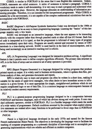
There are many different high-level languages. Table 2.6 describes several of the common high-level languages used for business and engineering applications. In Chapter 8 we describe the APT language, which is a high-level language used to program automatic machine tools.
Table 2.6 Some Common High-Level Computer Programming Languages for Business and Engineering Applications
2.7 Operating The Computer System
In the evolution of computer systems, one of the most important considerations has been the ease of operation of the system. Many technological improvements have been made which now make computer systems much easier to operate and much more efficient. For example, in early systems, the CPU and I/O operations could not take place independently. This meant that the CPU was forced to be idle while a slow input/output device transferred data to and from main memory. In modern computer systems, input/output and data processing operations can occur simultaneously to make the operation of the computer system more efficient. In this section we examine some of these techniques which facilitate the operation of the computer system by the user.
I/O control systems and operating systems
An input/output control system (IOCS) is a series of related programs which, when loaded into main storage, interpret I/O data transfer commands (such as READ and WRITE) and control the transfer of data to and from main storage. The IOCS also performs functions such as reading the labels on magnetic tape reels which are ready to be loaded, and it possesses features such as error-checking and recovery procedures for data-transfer operations.
An IOCS is designed to help improve computer operating efficiency. As the use of computers has increased, attention has also been focused on other areas that require control. One of these areas deals with the time wasted in the CPU between jobs. In early systems, the CPU was forced to remain idle while the operator manually staged the next job by mounting the correct tape or reading in the deck of cards. In present systems, processing of one job and input of another can occur concurrently by means of input/output channels and some sort of buffering system.
Another problem was the interaction of jobs requiring little CPU time but much I/O time, with those jobs that needed little I/O time but that monopolized the CPU. A solution to this problem involves placing both programs in memory simultaneously and executing parts of each for short intervals. To accomplish this, there must be a set of control programs to prevent the user programs from writing over each other in main memory, resulting in the destruction of both programs. This set of programs is called the operating system. Managing the various computer resources (CPU, memory, and I/O) and controlling peripheral devices are accomplished by the operating system. Unlike user programs, which support applications external to the computer system, an operating system supports the internal functions of the entire computing system. Its objective is to maximize the performance and efficiency of the system and to increase the ease with which the system can be used.
Virtual storage
A problem arises when a program requires more main storage than the computer possesses. For example, if there is 70K (1K equals 1024 bits) of main storage, and the user program requires 75K of storage, where does the computer acquire the additional 5K to execute the program?
With virtual storage, programs are not limited to memory locations in primary storage (main memory). Although each program instruction must be in main storage at the time it is executed, not all instructions must be there all the time. Maintaining only a portion of the program in real storage at any given time, and bringing in other portions as they are needed, increases the effective main memory available. This means that more user programs can be executing at one time; hence system throughput is increased.
Virtual storage is accomplished by one of two methods: segmentation and paging. In segmentation, the program is divided into variable-size blocks which represent logical program units such as subroutines and data groups. By monitoring each block’s location in a file called a segment table, the operating system loads only those segments needed by the part of the program currently being executed, and exchanges program segments as required.
Paging methods divide the usable main memory into fixed-size blocks called page frames. Programs and data are separated into units of the same size called pages. Page size depends on system hardware, and ranges from 1K to 4K bytes. The operating system monitors page frame usage, and as a program completes the current page, the next page is exchanged so that execution continues almost uninterrupted.
In both methods, virtual storage is achieved by the use of disk storage devices. The transfer of program and data units to and from main storage is handled by a program called the disk operating system (DOS). Segmentation and paging systems are sometimes combined into a single system to yield the benefits of both methods. More programs can be executed at a given time, for higher CPU and I/O device utilization.
Time sharing
Time sharing is a function on some operating systems that permits more than one user to have simultaneous access to a computer system. To each user, it seems as if the computer is giving its undivided attention. In reality, the computer is sharing its resources among many separate users. When CPU time is requested by a user terminal, a portion of main memory is assigned to that terminal. During operation, the CPU switches from one terminal to another, executing small portions of each program. When a particular program has completed execution, a new program is entered into the newly available memory space. The concept of many programs executing almost simultaneously with one CPU is called multiprogramming.
Time-sharing systems are of three major types:
1. General-purpose time-sharing systems that permit programmers to write and execute their own programs in various languages.
2. Execution-only systems that only allow users to execute programs, but not to create, alter, or delete programs.
3. Single-application systems in which all programs are related to a certain application area. In these systems, the user supplies the appropriate inputs and the system responds accordingly.
Distributed processing
Consistent with modern management philosophies for decentralization in the control of businesses, advances in computer technology have made possible a procedure called distributed computer processing. Although there is no universally accepted definition of the term, distributed processing generally refers to the use of “intelligent” terminals which can perform local editing and data manipulation and which can transmit partially processed data to a central computer facility for further work. This type of configuration also occurs when a communications network exists to facilitate the transfer of data from terminals to a central computer. Distributed processing allows geographically separate groups of users to accomplish much of their processing locally, but providing each group with access to a large central computer for jobs requiring a large mainframe and access to corporate data bases.
References
[1] BELZER, J., HOLZMANN, A. G., AND KENT, A., Encyclopedia of Computer Science and Technology, Vol. 11, Marcel Dekker, Inc., New York, 1978.
[2] BOHL, M., Information Processing, 2nd ed., Science Research Associates, Inc., Chicago, 1976.
[3] GOODSTEIN, D., “Output Alternatives,” Datamation, February, 1980, pp. 122–130.
[4] GROOVER, M. P., Automation, Production Systems, and Computer-Aided Manufacturing, Prentice-Hall, Inc., Englewood Cliffs, N.J., 1980, Chapter 11.
[5] KLINE, R. M., Digital Computer Design, Prentice-Hall, Inc., Englewood Cliffs, N.J., 1977.
[6] LEVENTHAL, L. A., Introduction to Microprocessors: Software, Hardware, Programming, Prentice-Hall, Inc., Englewood Cliffs, N.J., 1978.
[7] MACEVEN, G. H., Introduction to Computer Systems Using the PDP-11 and Pascal, McGraw-Hill Book Company, New York, 1980.
[8] MATICK, R. E., Computer Storage Systems and Technology, John Wiley ' Sons, Inc., New York, 1977.
[9] NASHELESKY, L., Introduction to Digital Computer Technology, 2nd ed., John Wiley ' Sons, Inc., New York, 1977.
[10] “Peripheral Equipment for Computers,” Electrical Engineering, Morgan-Grampian Ltd., London, November, 1978, pp. 107–116.
[11] ReCICAR, S., Selection of Data Entry Equipment, Special Publication 500-55, National Bureau of Standards, U.S. Dept. of Commerce, Washington, D.C., 1970.
[12] ROLPH, S., “The Disk Revolution,” Datamation, February, 1980, pp. 147–150.
[13] STEIN, D., “Videodisks—The Revolution in Information Storage,” Output Magazine, May, 1981, pp. 22–26.
[14] TANENBAUM, A. S., Structured Computer Organization, Prentice-Hall, Inc., Engle-wood Cliffs, N.J., 1976.
PROBLEMS
2.1 Determine the decimal equivalent for each of the following binary numbers.
(a) 001011
(b) 000101
(c) 010111
(d) 111111
2.2 Determine the binary equivalent for each of the following decimal numbers.
(a) 7
(b) 11
(c) 25
(d) 17
(e) 80
2.3 The decimal number system is based on the number 10. The binary number system is based on the number 2. Develop the framework (to four digits) for an octal number system (a number system based on the number 8). Use Table 2.4 as a framework for your model, but an abbreviated form would be adequate. Express the following decimal numbers in their octal equivalent.
(a) 8
(b) 73
(c) 116
(d) 1625
(e) 8000
2.4 Do Problem 2.3 except for a hexadecimal number system (a number system based on the number 16).