Chapter 4
Fundamentals of CAD
4.1Introduction
The computer has grown to become essential in the operations of business, government, the military, engineering, and research. It has also demonstrated itself, especially in recent years, to be a very powerful tool in design and manufacturing. In this and the following two chapters, we consider the application of computer technology to the design of a product. This chapter provides an overview of computer-aided design. Chapter 5 is concerned with the hardware components used in a CAD system. Chapter 6 describes some of the graphics software used for computer-aided design.
The CAD system defined
As defined in Chapter 1, computer-aided design involves any type of design activity which makes use of the computer to develop, analyze, or modify an engineering design. Modem CAD systems (also often called CAD/CAM systems) are based on interactive computer graphics (ICG). Interactive computer graphics denotes a user-oriented system in which the computer is employed to create, transform, and display data in the form of pictures or symbols. The user in the computer graphics design system is the designer, who communicates data and commands to the computer through any of several input devices. The computer communicates with the user via a cathode ray tube (CRT). The designer creates an image on the CRT screen by entering commands to call the desired software subroutines stored in the computer. In most systems, the image is constructed out of basic geometric elements—points, lines, circles, and so on. It can be modified according to the commands of the designer—enlarged, reduced in size, moved to another location on the screen, rotated, and other transformations. Through these various manipulations, the required details of the image are formulated.
The typical ICG system is a combination of hardware and software. The hardware includes a central processing unit, one or more workstations (including the graphics display terminals), and peripheral devices such as printers, plotters, and drafting equipment. Some of this hardware is shown in Figure 4.1. The software consists of the computer programs needed to implement graphics processing on the system. The software would also typically include additional specialized application programs to accomplish the particular engineering functions required by the user company.
It is important to note the fact that the ICG system is one component of a computer-aided design system. As illustrated in Figure 4.1, the other major component is the human designer. Interactive computer graphics is a tool used by the designer to solve a design problem. In effect, the ICG system magnifies the powers
Figure 4.1 Some of the important components in a computer-aided design system. (Courtesy of Computervision Corp.)
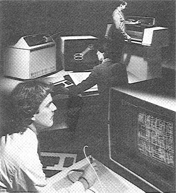
of the designer. This has been referred to as the synergistic effect. The designer performs the portion of the design process that is most suitable to human intellectual skills (conceptualization, independent thinking); the computer performs the task best suited to its capabilities (speed of calculations, visual display, storage of large amounts of data), and the resulting system exceeds the sum of its components.
There are several fundamental reasons for implementing a computer-aided design system:
1. To Increase the productivity of the designer. This is accomplished by helping the designer to visualize the product and its component subassemblies and parts; and by reducing the time required in synthesizing, analyzing, and documenting the design. This productivity improvement translates not only into lower design cost but also into shorter project completion times.
2. To improve the quality of design. A CAD system permits a more thorough engineering analysis and a larger number of design alternatives can be investigated. Design errors are also reduced through the greater accuracy provided by the system. These factors lead to a better design.
3. To improve communications. Use of a CAD system provides better engineering drawings, more standardization in the drawings, better documentation of the design, fewer drawing errors, and greater legibility.
4. To create a data base for manufacturing. In the process of creating the documentation for the product design (geometries and dimensions of the product and its components, material specifications for components, bill of materials, etc.), much of the required data base to manufacture the product is also created.
Historical perspective
The evolution of computer-aided design has been largely related to developments in computer graphics. Of course, CAD encompasses much more than computer graphics, as we shall discuss in the remainder of this chapter. However, ICG forms the essential technological foundation for computer-aided design. An excellent history of the development of computer graphics is presented in an article by Chasen [3]. We discuss some of the important highlights of his article in this section.
One of the significant initial projects in the area of computer graphics was the development of the APT language at the Massachusetts Institute of Technology in the middle and late 1950s. APT is an acronym for Automatically Programmed Tools, and this project was concerned with developing a convenient way to define geometry elements for numerical control part programming using the computer. We discuss numerical control programming, and in particular the APT language, in Chapter 8. Although the development of APT was an important milestone in the field of computer graphics, the early use of APT was not accomplished interactively.
Another concept which took form during the late 1950s was the “light pen.” The idea for this device came about during research on the processing of radar data for a defense project called SAGE (Semi-Automatic Ground Environment system). The purpose of the project was to develop a system to analyze radar data and to present possible bomber targets on a CRT display. To save time in displaying the interceptor aircraft against the bombers, the notion of using a light pen to identify a particular sector of the CRT screen was developed.
During the early 1960s, Ivan Sutherland worked on a project at MIT called “Sketchpad” and presented a paper on some of his results at the Fall Joint Computer Conference in 1963. The Sketchpad project is significant because it represents one of the first demonstrations of the creation and manipulation of images in real time on a CRT screen. To many observers, it marks the beginning of interactive computer graphics.
A number of large industrial concerns, including General Motors, IBM, Lockheed-Georgia, Itek Corp., and McDonnell (now McDonnell-Douglas), all became active in projects in computer graphics during the 1960s. Several of these projects eventually emerged in the form of commercial products (e.g., Unigraphics by McDonnell-Douglas and CADAM by Lockheed). In the late 1960s several CAD/CAM system vendors were also formed, including Calma in 1968 and Applicon and Computervision in 1969. These firms sell “turnkey” systems, which include all or most of the hardware and software components needed by the user. Other vendor firms have specialized in computer graphics software. One of the more familiar names in this area is Pat Hanratty, whose MCS Company developed the well-known AD 2000 (a later version is ANVIL 4000), a general-purpose software CAD package.
4.2 The Design Process
Before examining the several facets of computer-aided design, let us first consider the general design process. The process of designing something is characterized by Shigley [15] as an iterative procedure, which consists of six identifiable steps or phases:
1. Recognition of need
2. Definition of problem
3. Synthesis
4. Analysis and optimization
5. Evaluation
6. Presentation
Recognition of need involves the realization by someone that a problem exists for which some corrective action should be taken. This might be the identification of some defect in a current machine design by an engineer or the perception of a new product marketing opportunity by a salesperson. Definition of the problem involves a thorough specification of the item to be designed. This specification includes physical and functional characteristics, cost, quality, and operating performance.
Synthesis and analysis are closely related and highly iterative in the design process. A certain component or subsystem of the overall system is conceptualized by the designer, subjected to analysis, improved through this analysis procedure, and redesigned. The process is repeated until the design has been optimized within the constraints imposed on the designer. The components and subsystems are synthesized into the final overall system in a similar iterative manner.
Evaluation is concerned with measuring the design against the specifications established in the problem definition phase. This evaluation often requires the fabrication and testing of a prototype model to assess operating performance, quality, reliability, and other criteria. The final phase in the design process is the presentation of the design. This includes documentation of the design by means of drawings, material specifications, assembly lists, and so on. Essentially, the documentation requires that a design data base be created. Figure 4.2 illustrates the basic steps in the design process, indicating its iterative nature.
Engineering design has traditionally been accomplished on drawing boards, with the design being documented in the form of a detailed engineering drawing. Mechanical design includes the drawing of the complete product as well as its
Figure 4.2The general design process as defined by Shigley [13].

components and subassemblies, and the tools and fixtures required to manufacture the product. Electrical design is concerned with the preparation of circuit diagrams, specification of electronic components, and so on. Similar manual documentation is required in other engineering design fields (structural design, aircraft design, chemical engineering design, etc.). In each engineering discipline, the approach has traditionally been to synthesize a preliminary design manually and then to subject that design to some form of analysis. The analysis may involve sophisticated engineering calculations or it may involve a very subjective judgment of the aesthetc appeal possessed by the design. The analysis procedure identifies certain improvements that can be made in the design. As stated previously, the process is iterative. Each iteration yields an improvement in the design. The trouble with this iterative process is that it is time consuming. Many engineering labor hours are required to complete the design project.
4.3 The Application of Computers For Design
The various design-related tasks which are performed by a modern computer-aided design system can be grouped into four functional areas:
1. Geometric modeling
2. Engineering analysis
3. Design review and evaluation
4. Automated drafting
These four areas correspond to the final four phases in Shigley’s general design process, illustrated in Figure 4.3. Geometric modeling corresponds to the synthesis phase in which the physical design project takes form on the ICG system. Engineering analysis corresponds to phase 4, dealing with analysis and optimization. Design review and evaluation is the fifth step in the general design procedure. Automated drafting involves a procedure for converting the design image data residing in computer memory into a hard-copy document. It represents an important method for presentation (phase 6) of the design. The following four sections explore each of these four CAD functions.
Geometric modeling
In computer-aided design, geometric modeling is concerned with the computer-compatible mathematical description of the geometry of an object. The mathematical description allows the image of the object to be displayed and manipulated on a graphics terminal through signals from the CPU of the CAD system. The
Figure 4.3 Application of computers to the design process.

software that provides geometric modeling capabilities must be designed for efficient use both by the computer and the human designer.
To use geometric modeling, the designer constructs the graphical image of the object on the CRT screen of the ICG system by inputting three types of commands to the computer. The first type of command generates basic geometric elements such as points, lines, and circles. The second command type is used to accomplish scaling, rotation, or other transformations of these elements. The third type of command causes the various elements to be joined into the desired shape of the object being created on the ICG system. During this geometric modeling process, the computer converts the commands into a mathematical model, stores it in the computer data files, and displays it as an image on the CRT screen. The model can subsequently be called from the data files for review, analysis, or alteration.
There are several different methods of representing the object in geometric modeling. The basic form uses wire frames to represent the object. In this form
Figure 4.4 Example of wire-frame drawing of a part. (Courtesy of Computervision Corp.)
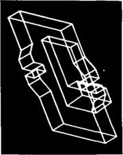
the object is displayed by interconnecting lines, as shown in Figure 4.4. Wire-frame geometric modeling is classified into three types, depending on the capabilites of the ICG system. The three types are:
1.2D. Two-dimensional representation is used for a flat object.
2.2 ½D. This goes somewhat beyond the 2D capability by permitting a three-dimensional object to be represented as long as it has no side-wall details.
3.3D. This allows for full three-dimensional modeling of a more complex geometry.
Even three-dimensional wire-frame representations of an object are sometimes inadequate for complicated shapes. Wire-frame models can be enhanced by several different methods. Figure 4.5 shows the same object shown in the previous figure but with two possible improvements. The first uses dashed lines to portray the rear edges of the object, those which would be invisible from the front. The second enhancement removes the hidden lines completely, thus providing a less cluttered
Figure 4.5 Same workpart as shown in Figure 4.4 but with (a) dashed lines to show rear edges of part, and (b) hidden-line removal. (Courtesy of Computervision Corp.)
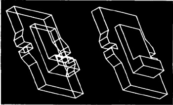
Figure 4.6 Solid model of yoke part as displayed on a computer graphics system. (Courtesy of Computervision Corp.)

picture of the object for the viewer. Some CAD systems have an automatic “hidden-line removal feature,” while other systems require the user to identify the lines that are to be removed from view. Another enhancement of the wire-frame model involves providing a surface representation which makes the object appear solid to the viewer. However, the object is still stored in the computer as a wire-frame model.
The most advanced method of geometric modeling is solid modeling in three dimensions. This method, illustrated in Figure 4.6, typically uses solid geometry shapes called primitives to construct the object. We shall discuss the difference between wire-frame and solid models in Chapter 6.
Another feature of some CAD systems is color graphics capability. By means of color, it is possible to display more information on the graphics screen. Colored images help to clarify components in an assembly, or highlight dimensions, or a host of other purposes. The benefits of color graphics are discussed in Chapter 5.
Engineering analysis
In the formulation of nearly any engineering design project, some type of analysis is required. The analysis may involve stress-strain calculations, heat-transfer computations, or the use of differential equations to describe the dynamic behavior of the system being designed. The computer can be used to aid in this analysis work. It is often necessary that specific programs be developed internally by the engineering analysis group to solve a particular design problem. In other situations, commercially available general-purpose programs can be used to perform the engineering analysis.
Turnkey CAD/CAM systems often include or can be interfaced to engineering analysis software which can be called to operate on the current design model.
We discuss two important examples of this type:
Analysis of mass properties
Finite-element analysis
The analysis of mass properties is the analysis feature of a CAD system that has probably the widest application. It provides properties of a solid object being analyzed, such as the surface area, weight, volume, center of gravity, and moment of inertia. For a plane surface (or a cross section of a solid object) the corresponding computations include the perimeter, area, and inertia properties.
Probably the most powerful analysis feature of a CAD system is the finite-element method. With this technique, the object is divided into a large number of finite elements (usually rectangular or triangular shapes) which form an interconnecting network of concentrated nodes. By using a computer with significant computational capabilities, the entire object can be analyzed for stress—strain, heat transfer, and other characteristics by calculating the behavior of each node. By determining the interrelating behaviors of all the nodes in the system, the behavior of the entire object can be assessed.
Some CAD systems have the capability to define automatically the nodes and the network structure for the given object. The user simply defines certain parameters for the finite-element model, and the CAD system proceeds with the computations.
The output of the finite-element analysis is often best presented by the system in graphical format on the CRT screen for easy visualization by the user. For example, in stress—strain analysis of an object, the output may be shown in the form of a deflected shape superimposed over the unstressed object. This is illustrated in Figure 4.7. Color graphics can also be used to accentuate the comparison
Figure 4.7 Finite-element modeling for stress-strain analysis. Graphics display shows strained part superimposed on unstrained part for comparison. (Courtesy of Applicon Inc.)
before and after deflection of the object. This is illustrated in Figure 5.6 for the same image as that shown in Figure 4.7. If the finite-element analysis indicates behavior of the design which is undesirable, the designer can modify the shape and recompute the finite-element analysis for the revised design.
Design review and evaluation
Checking the accuracy of the design can be accomplished conveniently on the graphics terminal. Semiautomatic dimensioning and tolerancing routines which assign size specifications to surfaces indicated by the user help to reduce the possibility of dimensioning errors. The designer can zoom in on part design details and magnify the image on the graphics screen for close scrutiny.
A procedure called layering is often helpful in design review. For example, a good application of layering involves overlaying the geometric image of the final shape of the machined part on top of the image of the rough casting. This ensures that sufficient material is available on the casting to accomplish the final machined dimensions. This procedure can be performed in stages to check each successive step in the processing of the part.
Another related procedure for design review is interference checking. This involves the analysis of an assembled structure in which there is a risk that the components of the assembly may occupy the same space. This risk occurs in the design of large chemical plants, air-separation cold boxes, and other complicated piping structures.
One of the most interesting evaluation features available on some computer-aided design systems is kinematics. The available kinematics packages provide the capability to animate the motion of simple designed mechanisms such as hinged components and linkages. This capability enhances the designer’s visualization of the operation of the mechanism and helps to ensure against interference with other components. Without graphical kinematics on a CAD system, designers must often resort to the use of pin-and-cardboard models to represent the mechanism. Commercial software packages are available to perform kinematic analysis. Among these are programs such as ADAMS (Automatic Dynamic Analysis of Mechanical Systems), developed at the University of Michigan. This type of program can be very useful to the designer in constructing the required mechanism to accomplish a specified motion and/or force.
Automated drafting
Automated drafting involves the creation of hard-copy engineering drawings directly from the CAD data base. In some early computer-aided design departments, automation of the drafting process represented the principal justification for investing in the CAD system. Indeed, CAD systems can increase productivity in the drafting function by roughly five times over manual drafting.
Some of the graphics features of computer-aided design systems lend them
Figure 4.8 Three views of a wire frame block: (a) oblique, (b) isometric, (c) perspective.

selves especially well to the drafting process. These features include automatic dimensioning, generation of crosshatched areas, scaling of the drawing, and the capability to develop sectional views and enlarged views of particular part details. The ability to rotate the part or to perform other transformations of the image (e.g., oblique, isometric, or perspective views), as illustrated in Figure 4.8, can be of significant assistance in drafting. Most CAD systems are capable of generating as many as six views of the part. Engineering drawings can be made to adhere to company drafting standards by programming the standards into the CAD system. Figure 4.9 shows an engineering drawing with four views displayed. This drawing was produced automatically by a CAD system. Note how much the isometric view promotes a higher level of understanding of the object for the user than the three orthographic views.
We discuss the various pieces of equipment for creating the hard-copy drawing in Section 5.5.
Parts classification and coding
In addition to the four CAD functions described above, another feature of the CAD data base is that it can be used to develop a parts classification and coding system. Parts classification and coding involves the grouping of similar part designs into classes, and relating the similarities by means of a coding scheme. Designers can use the classification and coding system to retrieve existing part designs rather than always redesigning new parts. There are several uses of such systems in manufacturing also, and we postpone further discussion of this subject until Chapter 12
4.4 Creating The Manufacturing Data Base
Section 4.3 has described the many ways in which computer-aided design can increase the productivity of the design department in the company. Another important reason for using a CAD system is that it offers the opportunity to
Figure 4.9 Engineering drawing with four views generated automatically by a CAD system. (From W. Fitzgerald, F. Gracer, and R. Wolfe, “GRIN: Interactive Graphics for Modeling Solids,” IBM Journal of Research and Development, Vol. 25, No. 4, July, 1981. Copyright 1981 by International Business Machines Corporation; reprinted with permission.)

develop the data base needed to manufacture the product. In the conventional manufacturing cycle practiced for so many years in industry, engineering drawings were prepared by design draftsmen and then used by manufacturing engineers to develop the process plan (i.e., the “route sheets”)– The activities involved in designing the product were separated from the activities associated with process planning. Essentially, a two-step procedure was employed. This was both time consuming and involved duplication of effort by design and manufacturing personnel. In an integrated CAD/CAM system, a direct link is established between product design and manufacturing. It is the goal of CAD/CAM not only to automate certain phases of design and certain phases of manufacturing, but also to automate the transition from design to manufacturing. Computer-based systems have been developed which create much of the data and documentation required to plan and manage the manufacturing operations for the product.
The manufacturing data base is an integrated CAD/CAM data base. It includes all the data on the product generated during design (geometry data, bill of materials and parts lists, material specifications, etc.) as well as additional data
Figure 4.10Desirable relationship of CAD/CAM data base to CAD and CAM.

required for manufacturing, much of which is based on the product design. Figure 4.10 shows how the CAD/CAM data base is related to design and manufacturing in a typical production-oriented company.
4.5 Benefits of Computer-Aided Design
There are many benefits of computer-aided design, only some of which can be easily measured. Some of the benefits are intangible, reflected in improved work quality, more pertinent and usable information, and improved control, all of which are difficult to quantify. Other benefits are tangible, but the savings from them show up far downstream in the production process, so that it is difficult to assign a dollar figure to them in the design phase. Some of the benefits that derive from implementing CAD/CAM can be directly measured. Table 4.1 provides a checklist of potential benefits of an integrated CAD/CAM system. In the subsections that follow, we elaborate on some of these advantages.
Productivity improvement in design
Increased productivity translates into a more competitive position for the firm because it will reduce staff requirements on a given project. This leads to lower costs in addition to improving response time on projects with tight schedules.
Surveying some of the larger CAD/CAM vendors, one finds that the productivity improvement ratio for a designer/draftsman is usually given as a range, typi
Table 4.1 Checklist of Potential Benefits That May Result from Implementing CAD as Part of an Integrated CAD/CAM System

cally from a low end of 3:1 to a high end in excess of 10:1 (often far in excess of that figure). There are individual cases in which productivity has been increased by a factor of 100, but it would be inaccurate to represent that figure as typical.
Productivity improvement in computer-aided design as compared to the traditional design process is dependent on such factors as:
Complexity of the engineering drawing
Level of detail required in the drawing
Degree of repetitiveness in the designed parts
Degree of symmetry in the parts
Extensiveness of library of commonly used entities
As each of these factors is increased, the productivity advantage of CAD will tend to increase.
Shorter lead times
Interactive computer-aided design is inherently faster than the traditional design process. It also speeds up the task of preparing reports and lists (e.g., the assembly lists) which are normally accomplished manually. Accordingly, it is possible with a CAD system to produce a finished set of component drawings and the associated reports in a relatively short time. Shorter lead times in design translate into shorter elapsed time between receipt of a customer order and delivery of the final product. The enhanced productivity of designers working with CAD systems will tend to reduce the prominence of design, engineering analysis, and drafting as critical time elements in the overall manufacturing lead time.
Design analysis
The design analysis routines available in a CAD system help to consolidate the design process into a more logical work pattern. Rather than having a back-and-forth exchange between design and analysis groups, the same person can perform the analysis while remaining at a CAD workstation. This helps to improve the concentration of designers, since they are interacting with their designs in a real-time sense. Because of this analysis capability, designs can be created which are closer to optimum. There is a time saving to be derived from the computerized analysis routines, both in designer time and in elapsed time. This saving results from the rapid response of the design analysis and from the time no longer lost while the design finds its way from the designer’s drawing board to the design analyst’s queue and back again.
An example of the success of this is drawn from the experience of the General Electric Company with the T700 engine [6]. In designing a jet engine, weight is an important design consideration. During the design of the engine, weights of each component for each design alternative must be determined. This had in the past been done manually by dividing each part into simple geometrical shapes to conveniently compute the volumes and weights. Through the use of CAD and its mass properties analysis function, the mass properties were obtained in 25% of the time formerly taken. The result of these calculations is illustrated in Fig. 4.11.
Since alterations in preliminary designs are generally easier to make and analyze with a CAD graphics system, more design alternatives can be explored and compared in the available development time. Consequently, it is reasonable to believe that a better design will result from the computer-aided design procedure.
Fewer design errors
Interactive CAD systems provide an intrinsic capability for avoiding design, drafting, and documentation errors. Data entry, transposition, and extension errors that occur quite naturally during manual data compilation for preparation of a bill of materials are virtually eliminated. One key reason for such accuracy is simply that
Figure 4.11 Weights of component parts as calculated by CAD system. (Reprinted by permission from Grimmer [6]).

no manual handling of information is required once the initial drawing has been developed. Errors are further avoided because interactive CAD systems perform time-consuming repetitive duties such as multiple symbol placement, and sorts by area and by like item, at high speeds with consistent and accurate results. Still more errors can be avoided because a CAD system, with its interactive capabilities, can be programmed to question input that may be erroneous. For example, the system might question a tolerance of 0.00002 in. It is likely that the user specified too many zeros. The success of this checking would depend on the ability of the CAD system designers to determine what input is likely to be incorrect and hence, what to question.
Greater accuracy in design calculations
There is also a high level of dimensional control, far beyond the levels of accuracy attainable manually. Mathematical accuracy is often to 14 significant decimal places. The accuracy delivered by interactive CAD systems in three-dimensional curved space designs is so far beyond that provided by manual calculation methods that there is no real comparison.
Computer-based accuracy pays off in many ways. Parts are labeled by the same recognizable nomenclature and number throughout all drawings. In some CAD systems, a change entered on a single item can appear throughout the entire documentation package, effecting the change on all drawings which utilize that part. The accuracy also shows up in the form of more accurate material and cost estimates and tighter procurement scheduling. These items are especially important in such cases as long-lead-time material purchases.
Standardization of design, drafting, and documentation procedures
The single data base and operating system is common to all workstations in the CAD system. Consequently, the system provides a natural standard for design/drafting procedures. With interactive computer-aided design, drawings are “standardized” as they are drawn; there is no confusion as to proper procedures because the entire format is “built into” the system program.
Drawings are more understandable
Interactive CAD is equally adept at creating and maintaining isometrics and oblique drawings as well as the simpler orthographies. All drawings can be generated and updated with equal ease. Thus an up-to-date version of any drawing type can always be made available.
In general, ease of visualization of a drawing relates directly to the projection used. Orthographic views are less comprehensible than isometrics. An isometric view is usually less understandable than a perspective view. Most actual construction drawings are “line drawings.” The addition of shading increases comprehension. Different colors further enhance understanding. Finally, animation of the images on the CRT screen allows for even greater visualization capability. The various relationships are illustrated in Figure 4.12.
Figure 4.12Improvement in visualization of images for various drawing types and computer graphics features.

Improved procedures for engineering changes
Control and implementation of engineering changes is significantly improved with computer-aided design. Original drawings and reports are stored in the data base of the CAD system. This makes them more accessible than documents kept in a drawing vault. They can be quickly checked against new information. Since data storage is extremely compact, historical information from previous drawings can be easily retained in the system’s data base, for easy comparison with current design/drafting needs.
Benefits in manufacturing
The benefits of computer-aided design carry over into manufacturing. As indicated previously, the same CAD/CAM data base is used for manufacturing planning and control, as well as for design. These manufacturing benefits are found in the following areas:
Tool and fixture design for manufacturing
Numerical control part programming
Computer-aided process planning
Assembly lists (generated by CAD) for production
Computer-aided inspection
Robotics planning
Group technology
Shorter manufacturing lead times through better scheduling
These benefits are derived largely from the CAD/CAM data base, whose initial framework is established during computer-aided design. We will discuss the many facets of computer-aided manufacturing in later chapters. In the remainder of this chapter, let us explore several applications that utilize computer graphics technology to solve various problems in engineering and related fields.
4.6 Some Examples
The following examples, with accompanying figures, were selected to demonstrate the capabilities and advantages of interactive computer graphics and computer-aided design. All the figures in this section were generated by computer, either in the form of a line drawing or as an image on the graphics screen. The reader should consider in all the examples the significant amount of human time and effort that would be required if the same illustrations were accomplished by hand, without the aid of a computer graphics system. We will provide a minimum of description in the examples. For the most part, the associated figures for each example speak for themselves.
Example 4.1
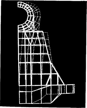
Computer-aided design systems can be used to solve design and engineering problems in architectural and construction applications. Figure 4.13 provides two illustrations of these applications. The top drawing shows a three-dimensional view of a building section which possesses an unusual curved layout. The top view and certain other projections of the building would represent a fairly straightforward drawing problem in manual drafting, but it would be difficult to manually construct the three dimensional view of the building. The CAD
Figure 4.13 Examples of architectural application using a computer-aided design system.(From W. Fitzgerald, F. Gracer, and R. Wolfe, “GRIN: Interactive Graphics for Modeling Solids,” IBM Journal of Research and Development, Vol. 25, No. 4, July, 1981. Copyright 1981 by International Business Machines Corporation; reprinted with permission.)

system, in this case with solids modeling capability, can generate the image of the building from any desired vantage point.
The lower drawing shows a three-dimensional floor plan of a house which adds a certain realism and perspective not achieved in a two-dimensional view. Both of these line drawings were generated using the GDP/GRIN system developed by IBM Corporation [5].
Example 4.2
In the design of many products with complicated mechanisms or potential interferences between components, it is important to be able to test the product for these characteristics. This has traditionally been done by constructing a physical model or prototype of the product. With an interactive computer graphics system capable of motion simulation and interference checking, these problems can be analyzed without the need for a physical model. Figure 4.14 illustrates this capability. A bulldozer design is shown in Figure 4.14(a) (component identification and arrows were added to the computer drawing). The analysis was carried out using a solids modeling system with dynamic simulation capability [5]. The objective of the analysis was to find the range of motion (lift and tilt) which could be applied to the bulldozer blade without causing interference. Rotation commands were given to lift the blade over a range of elevations. At each position of the blade, interference analysis was performed to determine if any components were touching or overlapping. Figure 4.14(b) shows the blade in one of its extreme rotational orientations.
Example 4.3
CAD/CAM systems have proven very useful in the design of integrated circuit devices [1]. Figure 4.15 shows a computer-generated design drawing of a LSI (large scale integrated)
Figure 4.14 Bulldozer blade design problem; results of blade lift and tilt motion. (From W. Fitzgerald, F. Gracer, and R. Wolfe, “GRIN: Interactive Graphics for Modeling Solids,” IBM Journal of Research and Development, Vol. 25, No. 4, July, 1981. Copyright 1981 by International Business Machines Corporation; reprinted with permission.)
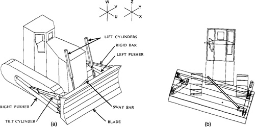
Figure 4.15 VLSI circut chip design. (Reprinted from Ayres [1] by permission.)

chip. This type of drawing can be developed from logic relationships which have been specified by the designer to define the function of the circuit. The drawing shows both the internal circuitry of the chip and the interface connectors at the periphery of the chip. CAD/CAM systems are useful in LSI design for generating the artwork required during fabrication of the chip. The complexity of this figure demonstrates the considerable trouble that would be involved in accomplishing the design manual methods.
Example 4.4
CAD/CAM systems are also useful in the manufacture of mechanical parts and products. Figures 4.16 and 4.17 illustrate two examples. Figure 4.16 shows two views of the same sheet metal part. The left-hand view shows the final part after it has been blanked and formed into the desired form. One of the problems encountered in pressworking of this kind is the problem of shearing the flat sheet metal to the proper size and shape so that it can be bent to the specified final dimensions. This is not only a problem of geometry, but also the flat size must be made slightly undersized to allow for stretching of the metal during the bending operations. CAD/CAM software has been written to perform the necessary computations to determine the correct dimensions of the flat part in sheet metal working. For the formed part in this example, the unbent flat is shown in the right-hand view.
Figure 4.17 shows a process drawing of a machined part that would be turned on a numerically controlled lathe. The hublike shape of the part in the left-hand view of the figure would be cut out of a round disk by means of a sequence of turning passes, as indicated by the series of horizontal lines. Numerically controlled machine tools operate according to a set of programmed instructions which control the machine’s actions in a step-by-step manner. The left-hand side of Figure 4.17 shows the types of programming instructions that would be used to control the lathe. CAD/CAM systems can be utilized to aid the programmer in preparing the part programs for numerical control. In some cases, the programming can be done almost automatically by the system with very little interaction by the user. We discuss the programming of numerical control machines in some detail in Chapter 8. In particular, we examine the use of CAD/CAM packages to perform numerical control part programming in Section 8.8.
Figure 4.16 Sheet metal part in bent final shape (left) and flat blank (right). (Courtesy of Computervision Corp.)

Figure 4.17 Machined part (left) and numerical control part program (right). (Courtesy of Computervision Corp.)

Example 4.5
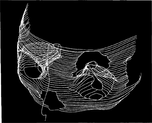
Figure 4.18 illustrates an interesting application of interactive computer graphics which falls outside the usual scope of computer-aided design and manufacturing. The figure shows a three-dimensional drawing of a child’s facial features, constructed from a high-resolution computed tomography (CT) scan. Tomography involves the use of X-ray techniques in which the shadows in front of and behind the sections of the subject under study do not show. The use of CT scans allows the three-dimensional bony and soft tissue surfaces to be reconstructed by computer software into the image illustrated in the figure. When applied to facial abnormalities in children, high-resolution CT scan techniques have provided an improved understanding of aberrant craniofacial anatomy in the medical community. These techniques have also been helpful in the planning of surgical operations and in improving postoperative care and evaluation.
Figure 4.18 Three-dimensional facial construction utilizing Computed Tomography (CT) scan. (Courtesy of McDonnell-Douglas Automation Company.)
These examples illustrate the significant opportunities and benefits offered by the use of interactive computer graphics and CAD/CAM systems. The following two chapters examine the hardware and software technologies of computer-aided design which make these applications possible.
References
[1] AYRES, R., VLSI: Silicon Compilation and the Art of Automatic Microchip Design, Prentice-Hall, Inc., Englewood Cliffs, N.J., 1983, Chapter 8.
[2] BYLDMSKI, G., “A New Industrial Revolution Is on the Way,” Fortune, October 5, 1981, pp. 106–114.
[3] CHASEN, S. H., “Historical Highlights of Interactive Computer Graphics,” Mechanical Engineering, November, 1981, pp. 32–41.
[4] CLAYTON, R. J., “CAD/CAM Integration: 2 + 2 = 5,” CAD/CAM Technology, Spring, 1982, pp. 21–26.
[5] FITZGERALD, W., GRACER, F., AND WOLFE, R., “GRIN: Interactive Graphics for Modeling Solids,” IBM Journal of Research and Development, July, 1981, pp. 281–294.
[6] GRIMMER, G., “Design and Manufacture of a Jet Engine,“ in The CAD/CAM Handbook, C. Machover and R. Blauth, Eds., Computervision Corp., Bedford, Mass., 1980, pp. 159–172.
[7] GROOVER, M. P., Automation, Production Systems, and Computer-Aided Manufacturing, Prentice-Hall, Inc., Englewood Cliffs, N.J., 1980, Chapter 10.
[8] INGLESBY, T., “CAD/CAM: Should We or Shouldn’t We?” Assembly Engineering, March, 1982, pp. 48–50.
[9] KROUSE, J. K., “CAD/CAM—Bridging the Gap from Design to Production,” Machine Design, June 12, 1980, pp. 117–125.
[10] LERRO, J. P., JR., “CAD/CAM System: More than an Automated Drafting Tool,“ Design News, November 17, 1980.
[11] LERRO, J. P., JR., “CAD/CAM System: Start of the Productivity Revolution,” Design News, November 16,1981, pp. 46–65.
[12] MACHOVER C., AND BLAUTH, R. E., Eds., The CAD/CAM Handbook, Computervision Corp., Bedford, Mass., 1980.
[13] MYERS, W., “InteractiveGraphics: FlyingHigh,” Computer, July, 1979, pp. 8–11.
[14] SCHAFFER, G., “Computer Graphics Goes to Work,” Special Report 724, American Machinist, July, 1980, pp. 149–164.
[15] SHIGLEY, J. E., Mechanical Engineering Design, 3rd ed., McGraw-Hill Book Company, New York, 1977.
[16] SMYTH, S. J., “CAD/CAM Data Handling from Conceptual Design through Product Support,” Journal of Aircraft, October, 1980, pp. 753–760.