Chapter 10
Robot Technology1
1 Portions of this chapter and the following chapter are based on Groover [6,7].
10.1 Introduction
An industrial robot is a general-purpose, programmable machine possessing certain anthropomorphic characteristics. The most typical anthropomorphic, or humanlike, characteristic of a robot is its arm. This arm, together with the robot’s capacity to be programmed, makes it ideally suited to a variety of production tasks, including machine loading, spot welding, spray painting, and assembly. The robot can be programmed to perform a sequence of mechanical motions, and it can repeat that motion sequence over and over until reprogrammed to perform some other job.
An industrial robot shares many attributes in common with a numerical control machine tool. The same type of NC technology used to operate machine tools is used to actuate the robot’s mechanical arm. The robot is a lighter, more portable piece of equipment than an NC machine tool. The uses of the robot are more general, typically involving the handling of workparts. Also, the programming of the robot is different from NC part programming. Traditionally, NC programming has been performed off-line with the machine commands being contained on a punched tape. Robot programming has usually been accomplished on-line, with the instructions being retained in the robot’s electronic memory. In spite of these differences, there are definite similarities between robots and NC machines in terms of power drive technologies, feedback systems, the trend toward computer control, and even some of the industrial applications.
The popular concept of a robot has been fashioned by science fiction novels and movies such as “Star Wars.” These images tend to exaggerate the robot’s similarity to human anatomy and behavior. The human analogy has sometimes been a troublesome issue in industry. People tend to associate the future use of advanced robots in factories with high unemployment and the subjugation of human beings by these machines.
Largely in response to this humanoid conception associated with robots, there have been attempts to develop definitions which reduce the anthropomorphic impact. The Robot Institute of America has developed the following definition:
A robot is a programmable, multi-function manipulator designed to move material, parts, tools, or special devices through variable programmed motions for the performance of a variety of tasks.
Attempts have even been made to rename the robot. George Devol, one of the original inventors in robotics technology, called his patent application by the name “programmed article transfer.” For many years, the Ford Motor Company used the term “universal transfer device” instead of “robot.” Today the term “robot” seems to have become entrenched in the language, together with whatever humanlike characteristics people have attached to the device.
10.2 Robot Physical Configurations
Industrial robots come in a variety of shapes and sizes. They are capable of various arm manipulations and they possess different motion systems. This section discusses the various physical configurations of robots. The following section deals with robot motion systems. Section 10.4 is concerned with most of the remaining technical features by which industrial robots are distinguished. Other topics, such as robot programming and gripper devices, are covered in the remaining sections.
Almost all present-day commercially available industrial robots have one of the following four configurations:
1. Polar coordinate configuration
2. Cylindrical coordinate configuration
3. Jointed arm configuration
4. Cartesian coordinate configuration
The four types are schematically illustrated in Figure 10.1 and described below.
Figure 10.1 The four most common robot configurations: (a) polar coordinate; (b) cylindrical coordinate; (c) jointed arm configuration; (d) cartesian coordinate. (Reprinted from Toepperwein et al. [15].)

Figure 10.2 Unimate 2000 series robot—polar coordinate configuration. (Courtesy of Unimation Inc.)
Polar coordinate configuration
This configuration also goes by the name “spherical coordinate,” because the workspace within which it can move its arm is a partial sphere. As shown in Figure 10.1 (a), the robot has a rotary base and a pivot that can be used to raise and lower a telescoping arm. One of the most familiar robots, the Unimate Model 2000 series, was designed around this configuration, and is pictured in Figure 10.2.
Cylindrical coordinate configuration
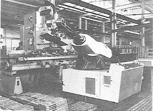
In this configuration, the robot body is a vertical column that swivels about a vertical axis. The arm consists of several orthogonal slides which allow the arm to be moved up or down and in and out with respect to the body. This is illustrated schematically in Figure 10.1(b). The Prab Versatran Model FC, pictured in Figure 10.3, is an example of the cylindrical coordinate design.
Jointed arm configuration
The jointed arm configuration is similar in appearance to the human arm, as shown in Figure 10.1(c). The arm consists of several straight members connected by joints which are analogous to the human shoulder, elbow, and wrist. The robot arm
Figure 10.3 Prab FC model robot—cylindrical configuration. (Courtesy of Prab Conveyors Inc.)

is mounted to a base which can be rotated to provide the robot with the capacity to work within a quasi-spherical space. The Cincinnati Milacron T3 model (Figure 10.4) and the Unimate PUMA model (Figure 10.5) are examples of this general configuration.
Cartesian coordinate configuration
A robot which is constructed around this configuration consists of three orthogonal slides, as pictured in Figure 10.1(d). The three slides are parallel to the x, y, and z axes of the cartesian coordinate system. By appropriate movements of these slides, the robot is capable of moving its arm to any point within its three-dimensional rectangularly shaped workspace.
10.3 Basic Robot Motions
Whatever the configuration, the purpose of the robot is to perform a useful task. To accomplish the task, an end effector, or hand, is attached to the end of the robot’s arm. It is this end effector which adapts the general-purpose robot to a particular
Figure 10.4 Cincinnati Milacron T3 robot—jointed arm configuration. (Courtesy of Cincinnati Milacron, Inc.)
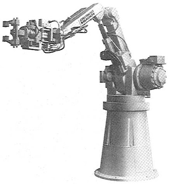
Figure 10.5 Unimation PUMA 500 robot—jointed arm configuration. (Courtesy of Unimation, Inc.)

task. To do the task, the robot arm must be capable of moving the end effector through a sequence of motions and/or positions.
Six degrees of freedom
There are six basic motions, or degrees of freedom, which provide the robot with the capability to move the end effector through the required sequence of motions. These six degrees of freedom are intended to emulate the versatility of movement possessed by the human arm. Not all robots are equipped with the ability to move in all six degrees. The six basic motions consist of three arm and body motions and three wrist motions, as illustrated in Figure 10.6 for the polar-type robot. These motions are described below.
Arm and body motions:
1. Vertical traverse: up-and-down motions of the arm, caused by pivoting the entire arm about a horizontal axis or moving the arm along a vertical slide
2. Radial traverse: extension and retraction of the arm (in-and-out movement)
3. Rotational traverse: rotation about the vertical axis (right or left swivel of the robot arm)
Figure 10.6 Typical six degrees of freedom in robot motion.
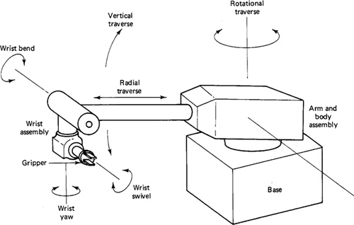
4. Wrist swivel: rotation of the wrist
5. Wrist bend: up-or-down movement of the wrist, which also involves a rotational movement
6. Wrist yaw: right-or-left swivel of the wrist
Additional axes of motion are possible, for example, by putting the robot on a track or slide. The slide would be mounted in the floor or in an overhead track system, thus providing a conventional six-axis robot with a seventh degree of freedom. The gripper device is not normally considered to be an additional axis of motion.
Motion systems
Similar to NC machine tool systems, the motion systems of industrial robots can be classified as either point-to-point (PTP) or contouring (also called continuous path).
In PTP, the robot’s movement is controlled from one point location in space to another. Each point is programmed into the robot’s control memory and then played back during the work cycle. No particular attention is given to the path followed by the robot in its move from one point to the next. Point-to-point robots would be quite capable of performing certain kinds of productive operations, such as machine loading and unloading, pick-and-place activities, and spot welding.
Contouring robots have the capability to follow a closely spaced locus of points which describe a smooth compound curve. The memory and control requirements are greater for contouring robots than for PTP because the complete path taken by the robot must be remembered rather than merely the end points of the motion sequence. However, in certain industrial operations, continuous control of the work cycle path is essential to the use of the robot in the operation. Examples of these operations are paint spraying, continuous welding processes, and grasping objects moving along a conveyor.
10.4 Other Technical Features
In addition to the robot’s physical configuration and basic motion capabilities, there are numerous other technical features of an industrial robot which determine its efficiency and effectiveness at performing a given task. The following are some of the most important among these technical features:
1. Work volume
2. Precision of movement
4. Weight-carrying capacity
5. Type of drive system
These features are described in this section.
Work volume
The term “work volume” refers to the space within which the robot can operate. To be technically precise, the work volume is the spatial region within which the end of the robot’s wrist can be manipulated. Robot manufacturers have adopted the policy of defining the work volume in terms of the wrist end, with no hand or tool attached.
The work volume of an industrial robot is determined by its physical configuration, size, and the limits of its arm and joint manipulations. The work volume of a cartesian coordinate robot will be rectangular. The work volume of a cylindrical coordinate robot will be cylindrical. A polar coordinate configuration will generate a work volume which is a partial sphere. The work volume of a jointed arm robot will be somewhat irregular, the outer reaches generally resembling a partial sphere. Robot manufacturers usually show a diagram of the particular model’s work volume in their marketing literature, providing a top view and side view with dimensions of the robot’s motion envelope.
Precision of movement
The precision with which the robot can move the end of its wrist is a critical consideration in most applications. In robotics, precision of movement is a complex issue, and we will describe it as consisting of three attributes:
1. Spatial resolution
2. Accuracy
3. Repeatability
These attributes are generally interpreted in terms of the wrist end with no end effector attached and with the arm fully extended.
SPATIAL RESOLUTION. The term “spatial resolution” refers to the smallest increment of motion at the wrist end that can be controlled by the robot. This is determined largely by the robot’s control resolution, which depends on its position control system and/or its feedback measurement system. In addition, mechanical inaccuracies in the robot’s joints would tend to degrade its ability to position its arm. The spatial resolution is the sum of the control resolution plus these mechanical inaccuracies. The factors determining control resolution are the range of movement of the arm and the bit storage capacity in the control memory for that movement. The arm movement must be divided into its basic motions or degrees of freedom, and the resolution of each degree of freedom is figured separately. Then the total control resolution is the vector sum of each component. An example will serve to illustrate this.
Example 10.1
Assume that we want to find the spatial resolution for a cartesian coordinate robot that has two degrees of freedom. The two degrees of freedom are manifested by two orthogonal slides. Each slide has a range of 0.4 m (about 15.75 in.), hence giving the robot a work volume which is a plane square, with 0.4 m on a side. Suppose that the robot’s control memory has a 10-bit storage capacity for each axis.
To determine the control resolution, we must first determine the number of control increments of which the control memory is capable. For the 10-bit storage, there are 210 = 1024 control increments (the number of distinct zones into which the slide range of 0.4 m can be divided).
Then the control resolution would be found by dividing the slide range by the number of control increments:
![]()
Since there are two orthogonal slides, the control resolution of this robot would be a square with 0.39 mm per side. Any mechanical inaccuracies would be added to this figure to get the spatial resolution.
This example shows that the spatial resolution can be improved by increasing the bit capacity of the robot’s control memory. Also, for a given memory capacity, a larger robot would have a poorer (larger) spatial resolution than a small robot. In reality, the spatial resolution would be worse (larger) than the control resolution computed in Example 10.1 because of mechanical inaccuracies in the slides.
ACCURACY. The accuracy of the robot refers to its capability to position its wrist end (or a tool attached to the wrist) at a given target point within its work volume. Accuracy is closely related to spatial resolution, since the robot’s ability to reach a particular point in space depends on its ability to divide its joint movements into small increments. According to this relation, the accuracy of the robot would be one-half the distance between two adjacent resolution points. This definition is illustrated in Figure 10.7. The robot’s accuracy is also affected by mechanical inaccuracies, such as deflection of its components, gear inaccuracies, and so forth.
REPEATABILITY. This refers to the robot’s ability to position its wrist end (or tool) back to a point in space that was previously taught. Repeatability is different from accuracy. The difference is illustrated in Figure 10.8. The robot was initially
Figure 10.7 Illustration of accuracy versus resolution.

Figure 10.8 Illustration of repeatability versus accuracy.

programmed to move the wrist end to the target point T. Because it is limited by its accuracy, the robot was only capable of achieving point A. The distance between points A and T is the accuracy. Later, the robot is instructed to return to this previously programmed point A. However, because it is limited by it repeatability, it is only capable of moving to point R. The distance between points R and A is a measure of the robot’s repeatability. As the robot is instructed to return to the same position in subsequent work cycles, it will not always return to point R, but instead will form a cluster of positions about point A. Repeatability errors form a random variable. In general, repeatability will be better (less) than accuracy. Mechanical inaccuracies in the robot’s arm and wrist components are principal sources of repeatability errors.
Speed of movement
The speed with which the robot can manipulate the end effector ranges up to a maximum of about 1.5 m/s. Almost all robots have an adjustment to set the speed to the desirable level for the task performed. This speed should be determined by such factors as the weight of the object being moved, the distance moved, and the precision with which the object must be positioned during the work cycle. Heavy objects cannot be moved as fast as light objects because of inertia problems. Also, objects must be moved more slowly when high positional accuracy is required.
Weight-carrying capacity
The weight-carrying capacity of commercially available robots covers a wide range. At the upper end of the range, there are robots capable of lifting over 1000 Ib. The Versatran FC model has a maximum load-carrying capacity rated at 2000 Ib. At the lower end of the range, the Unimate PUMA Model 250 has a load capacity of only 2.5 Ib. What complicates the issue for the low-weight-capacity robots is that the rated capacity includes the weight of the end effector. For example, if the gripper for the PUMA 250 weighs 1 Ib, the net capacity of the robot is only 1.5 Ib.
Type of drive system
There are three basic drive systems used in commercially available robots:
1. Hydraulic
2. Electric motor
3. Pneumatic
Hydraulically driven robots are typified by the Unimate 2000 series robots (Figure 10.2) and the Cincinnati Milacron T3 (Figure 10.4). These drive systems are usually associated with large robots, and the hydraulic drive system adds to the floor space required by the robot. Advantages which this type of system gives to the robot are mechanical simplicity (hydraulic systems are familiar to maintenance personnel), high strength, and high speed.
Robots driven by electric motors (dc stepping motors or servomotors) do not possess the physical strength or speed of hydraulic units, but their accuracy and repeatability is generally better. Less floor space is required due to the absence of the hydraulic power unit.
Pneumatically driven robots are typically smaller and technologically less sophisticated than the other two types. Pick-and-place tasks and other simple, high-cycle-rate operations are examples of the kinds of applications usually reserved for these robots.
10.5 Programming the Robot
There are various methods by which robots can be programmed to perform a given work cycle. We divide these programming methods into four categories:
1. Manual method
2. Walkthrough method
4. Off-line programming
Manual method
This method is not really programming in the conventional sense of the word. It is more like setting up a machine rather than programming. It is the procedure used for the simpler robots and involves setting mechanical stops, cams, switches, or relays in the robot’s control unit. For these low-technology robots used for short work cycles (e.g., pick-and-place operations), the manual programming method is adequate.
Walkthrough method
In this method the programmer manually moves the robot’s arm and hand through the motion sequence of the work cycle. Each movement is recorded into memory for subsequent playback during production. The speed with which the movements are performed can usually be controlled independently so that the programmer does not have to worry about the cycle time during the walkthrough. The main concern is getting the position sequence correct. The walkthrough method would be appropriate for spray painting and arc welding robots.
Leadthrough method
The leadthrough method makes use of a teach pendant to power drive the robot through its motion sequence. The teach pendant is usually a small hand-held device with switches and dials to control the robot’s physical movements. Each motion is recorded into memory for future playback during the work cycle. The leadthrough method is very popular among robot programming methods because of its ease and convenience.
Off-line programming
This method involves the preparation of the robot program off-line, in a manner similar to NC part programming. Off-line robot programming is typically accomplished on a computer terminal. After the program has been prepared, it is entered into the robot memory for use during the work cycle. The advantage of off-line robot programming is that production time of the robot is not lost to delays in teaching the robot a new task. Programming off-line can be done while the robot is still in production on the preceding job. This means higher utilization of the robot and the equipment with which it operates.
Another benefit associated with off-line programming is the prospect of integrating the robot into the factory CAD/CAM data base and information system. In future manufacturing systems, robot programming will be performed by advanced CAD/CAM systems, just as NC part programs can be generated by today’s CAD/CAM technology.
10.6 Robot Programming Languages
Non-computer-controlled robots do not require a programming language. They are programmed by the walkthrough or leadthrough methods while the simpler robots are programmed by manual methods. With the introduction of computer control for robots came the opportunity and the need to develop a computer-oriented robot programming language. In this section we discuss two of these languages: VAL, developed for the Unimation PUMATM robot; and MCL, and APT-based language developed by McDonnell-Douglas Corporation.
The VALTM language
The VAL language was developed by Victor Scheinman for the PUMA robot, an assembly robot produced by Unimation Inc. Hence, VAL stands for Victor’s Assembly Language. It is basically an off-line language in which the program defining the motion sequence can be developed off-line, but the various point locations used in the work cycle are most conveniently defined by leadthrough.
VAL statements are divided into two categories, Monitor Commands and Programming Instructions.
The Monitor Commands are a set of administrative instructions that direct the operation of the robot system. The Monitor Commands would be used for such functions as:
Preparing the system for the user to write programs for the PUMA
Defining points in space
Commanding the PUMA to execute a program
Listing programs on the CRT
Some of the important Monitor Commands are given in Table 10.1, together with a description of the command and one or more examples showing how it would be entered.
The Program Instructions are a set of statements used to write robot programs. Programs in VAL direct the sequence of motions of the PUMA. One statement usually corresponds to one movement of the robot’s arm or wrist. Examples of Program Instructions include:
Move to a point.
Move to a point in a straight-line motion.
Open gripper.
Close gripper.
Table 10.1 Common Monitor Commands in VAL
Source: Adapted from Ref. [16].
The Program Instructions are entered into memory to form programs by first using the Monitor Command EDIT. This prepares the system to receive the Program Instruction statements in the proper order. Some of the important Program Instructions are given in Table 10.2. Each instruction is described and examples are given to illustrate typical usage.
The statements listed in Tables 10.1 and 10.2 are only a few of the many VAL commands. Reference [16] provides a comprehensive presentation of VAL and its many statements. The following example will illustrate the programming language.
Example 10.2
This example deals with a pick-and-place operation, in which the robot is instructed to pick up a workpart from one conveyor (point A) and place it on another conveyor (point B). The VAL program for this work cycle is presented in Figure 10.9. Figure 10.10 shows the PUMA locations for points A and B in the program. The listing gives the PUMA’s x, y, and z coordinate positions (joints 1, 2, and 3), as well as the three wrist joint positions (joints 4, 5, and 6) for the two points, A and B.
The MCL language
The MCL stands for Machine Control Language and was developed by McDonnell-Douglas Corporation under contract to the U.S. Air Force ICAM
Table 10.2 Common Programming Instructions in VAL
Source: Adapted from Ref. [16].
Figure 10.9 Simple robot program listing for Example 10.2 using Unimation’s VAL language.

Figure 10.10 Listing of joint positions for Unimate PUMA 600 robot in Example 10.2.

(Integrated Computer-Aided Manufacturing) Program [10]. The language is based on the APT NC language, but is designed to control a complete manufacturing cell, including a cell with robots. MCL is an enhancement of APT which possesses additional options and features needed to do off-line programming of a robotic work cell.
Additional vocabulary words were developed to provide the supplementary capabilities intended to be covered by the MCL language. These capabilities include vision, inspection, and the control of signals to and from the various devices that constitute the robotic workstation. A list of some of these vocabulary words is presented in Table 10.3. MCL also permits the user to define MACRO-like statements that would be convenient to use for specialized applications.
After the MCL program has been written, it is compiled to produce the CLFILE as output. The definition of the CLFILE has been extended to accommodate the new MCL features that go beyond the conventional cutter location data in APT. The extensions include such capabilities as:
The definition of the various devices within the work cell and the tasks which are performed by these devices
Predefined frames of reference which are associated with the different machines or devices in the cell
User-defined frames of reference which could be used for defining the geometry of the workpart
The part identification and acquisition within the work cell
MCL represents a significant enhancement of APT which can be used to perform off-line programming of complex robotic work cells.
Table 10.3 Some Representative Programming Words in MCL

Source: Adapted from Ref. [11].
10.7 End Effectors
In the terminology of robotics, an end effector can be defined as a device which is attached to the robot’s wrist to perform a specific task. The task might be workpart handling, spot welding, spray painting, or any of a great variety of other functions. The possibilities are limited only by the imagination and ingenuity of the applications engineers who design robot systems. (Economic considerations might also impose a few limitations.) The end effector is the special-purpose tooling which enables the robot to perform a particular job. It is usually custom engineered for that job, either by the company that owns the robot or by the company that sold the robot. Most robot manufacturers have engineering groups which design and fabricate end effectors or provide advice to their customers on end effector design.
For purposes of organization, we will divide the various types of end effectors into two categories: grippers and tools. The following two sections discuss these two categories.
Grippers
Grippers are used to hold either workparts (in pick-and-place operations, machine loading, or assembly work) or tools. There are numerous alternative ways in which the gripper can be designed. The most appropriate design depends on the workpart or substance being handled. The following is a list of the most common grasping methods used in robot grippers:
Mechanical grippers, where friction or the physical configuration of the gripper retains the object
Suction cups (also called vacuum cups), used for flat objects
Magnetized gripper devices, used for ferrous objects
Hooks, used to lift parts off conveyors
Scoops or ladles, used for fluids, powders, pellets, or granular substances
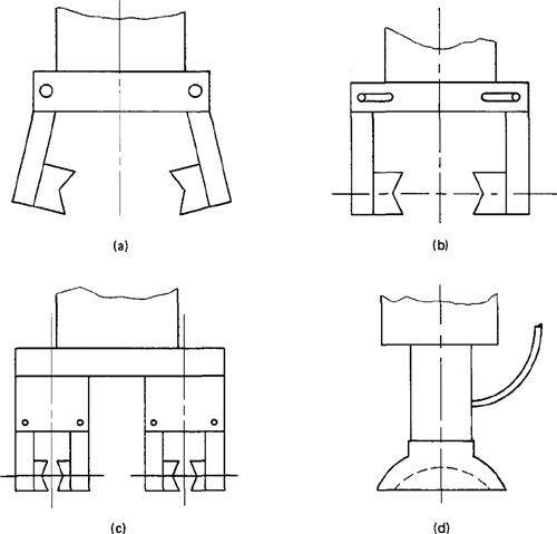
Several alternative gripper designs are illustrated in Figure 10.11.
Tools as end effectors
There are a limited number of applications in which a gripper is used to grasp a tool and use it during the work cycle. In most applications where the robot manipulates a tool during the cycle, the tool is fastened directly to the robot wrist and becomes the end effector. A few examples of tools used with robots are the following:
Spot welding gun
Arc welding tools (and wire-feed mechanisms)
Figure 10.11 Sample gripper designs: (a) pivot action gripper; (b) slide action gripper; (c) double gripper—pivot action mechanism; (d) vacuum-operated hand.
Spray painting gun
Drilling spindle
Routers, grinders, wire brushes
Heating torches
In some of these examples, quick-change mechanisms can be incorporated into the tool design to allow for fast changeover from one size or type to the next.
10.8 Work Cell Control and Interlocks
Work Cell control
Industrial robots usually work with other things: processing equipment, workparts, conveyors, tools, and perhaps, human operators. A means must be provided for coordinating all of the activities which are going on within the robot workstation. Some of the activities occur sequentially, while others take place simultaneously. To make certain that the various activities are coordinated and occur in the proper sequence, a device called the work cell controller is used (another name for this is workstation controller). The work cell controller usually resides within the robot and has overall responsibility for regulating the activities of the work cell components. To illustrate the kinds of problems and issues that would have to be managed by the work cell controller, consider the following example of a relatively simple machine loading application.
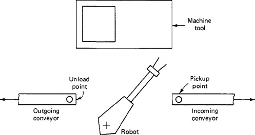
Example 10.3
The workstation consists of the robot; the machine tool, which operates on a semiautomatic cycle; and two conveyors, one for incoming raw workparts and the other for outgoing finished pieces. The setup is shown in Figure 10.12. The work cycle consists of the following activities:
1. Incoming conveyor delivers raw workpart to fixed position.
2. Robot picks up part from conveyor and loads it into machine.
3. Machine processes workpart.
4. Robot unloads finished part from machine and places it on outgoing conveyor.
5. Outgoing conveyor delivers part out of work cell, and robot returns to ready position near incoming conveyor.
As this work cycle is described, most of the activities occur sequentially. The work cell controller would have to make sure that certain steps are completed before subsequent steps are initiated. For example, the machine tool must finish processing the workpart before the robot attempts to reach in and grasp the part for unloading. Similarly, the machine cycle must not begin until the robot has loaded the raw workpiece and removed its arm. The robot cannot pick up the raw part from the incoming conveyor unless and until the part has been
Figure 10.12 Workplace layout for robot cell of Example 10.3.
positioned for gripping. The purpose of the work cell controller in this example is to ensure that the work elements are sequenced correctly and that each step is finished before the next one begins.
Although most of the activities occur sequentially, some of the devices perform their functions simultaneously. For example, the conveyors continue to deliver workparts into and out of the work cell while the machine tool is operating. In two of the exercise problems at the end of the chapter, we require the reader to consider improvements that might be made in this work cycle to increase production rate.
This example illustrates several of the functions that must be performed by the work cell controller. These functions include:
1. Controlling the sequence of activities in the work cycle.
2. Controlling simultaneous activities.
3. Making decisions to proceed based on incoming signals.
Additional functions that might be required of the work cell controller (in more sophisticated work cells) are:
4. Making logical decisions.
5. Performing computations.
6. Dealing with exceptional events, such as broken tools or equipment breakdowns.
7. Performing irregular cycles, such as periodically changing tools.
To enable it to carry out these functions, the work cell controller must receive signals from other devices in the work cell, and it must communicate signals to the various components of the work cell. These signals are accomplished by means of interlocks and sensors.
Interlocks
An interlock is the feature of work cell control which prevents the work cycle sequence from continuing until a certain condition or set of conditions has been satisfied. In a robotic work cell, there are two types: outgoing and incoming. The outgoing interlock is a signal sent from the workstation controller to some external machine or device that will cause it to operate or not operate. For example, this would be used to prevent a machine from initiating its process until it was commanded to proceed by the work cell controller. An incoming interlock is a signal from some external machine or device to the work controller which determines whether or not the programmed work cycle sequence will proceed. For example, this would be used to prevent the work cycle program from continuing until the machine signaled that it had completed its processing of the workpiece.
The use of interlocks provides an important benefit in the control of the work cycle because it prevents actions from happening when they shouldn’t, and it causes actions to occur when they should. Interlocks are needed to help coordinate the activities of the various independent components in the work cell and to help avert damage of one component by another.
In the planning of interlocks in the robotic work cell, the applications engineer must consider both the normal sequence of activities that will occur during the work cycle, and the potential malfunctions that might occur. Then these normal activities are linked together by means of limit switches, pressure switches, photoelectric devices, and other system components. Malfunctions that can be anticipated are prevented by means of similar devices.
10.9 Robotic Sensors
For certain robot applications, the type of workstation control using interlocks is not adequate. The robot must take on more humanlike senses and capabilities in order to perform the task in a satisfactory way. These senses and capabilities include vision and hand—eye coordination, touch, and hearing. Accordingly, we will divide the types of sensors used in robotics into the following three categories:
1. Vision sensors
2. Tactile and proximity sensors
3. Voice sensors
It is beyond the scope of this chapter to provide more than a brief survey of this fascinating topic. For additional study, Refs. [1], [3], [5], [9], [10], [15], and [17] are recommended.
Vision sensors
This is one of the areas that is receiving a lot of attention in robotics research. Computerized visions systems will be an important technology in future automated factories. Robot vision is made possible by means of a video camera, a sufficient light source, and a computer programmed to process image data. The camera is mounted either on the robot or in a fixed position above the robot so that its field of vision includes the robot’s work volume. The computer software enables the vision system to sense the presence of an object and its position and orientation. Vision capability would enable the robot to carry out the following kinds of operations:
Retrieve parts which are randomly oriented on a conveyor.
Recognize particular parts which are intermixed with other objects.
Perform visual inspection tasks.
Perform assembly operations which require alignment.
All of these operations have been accomplished in research laboratories. It is merely a matter of time and economics before vision sensors become a common feature in robot applications.
Tactile and proximity sensors
Tactile sensors provide the robot with the capability to respond to contact forces between itself and other objects within its work volume. Tactile sensors can be divided into two types:
1. Touch sensors
2. Stress sensors (also called force sensors)
Touch sensors are used simply to indicate whether contact has been made with an object. A simple microswitch can serve the purpose of a touch sensor. Stress sensors are used to measure the magnitude of the contact force. Strain gage devices are typically employed in force-measuring sensors.
Potential uses of robots with tactile sensing capabilities would be in assembly and inspection operations. In assembly, the robot could perform delicate part alignment and joining operations. In inspection, touch sensing would be useful in gauging operations and dimensional-measuring activities. Proximity sensors are used to sense when one object is close to another object. On a robot, the proximity sensor would be located on or near the end effector. This sensing capability can be engineered by means of optical-proximity devices, eddy-current proximity detectors, magnetic-field sensors, or other devices.
In robotics, proximity sensors might be used to indicate the presence or absence of a workpart or other object. They could also be helpful in preventing injury to the robot’s human coworkers in the factory.
Voice sensors
Another area of robotics research is voice sensing or voice programming. Voice programming can be defined as the oral communication of commands to the robot or other machine. (Voice programming is also used in NC part programming and the reader is invited to refer back to Section 8.9 for a description of this interesting application.) The robot controller is equipped with a speech recognition system which analyzes the voice input and compares it with a set of stored word patterns. When a match is found between the input and the stored vocabulary word, the robot performs some action which corresponds to that word.
Voice sensors would be useful in robot programming to speed up the programming procedure, just as it does in NC programming. It would also be beneficial in especially hazardous working environments for performing unique operations such as maintenance and repair work. The robot could be placed in the hazardous environment and remotely commanded to perform the repair chores by means of step-by-step instructions.
References
[1] AGIN, G. J., “Real-Time Robot Control with a Mobile Camera,” Robotics Today, Fall, 1979, pp. 35–39.
[2] ALLAN, J. J. (Ed.), A Survey of Industrial Robots, Productivity International, Inc., Dallas, Tex., 1980.
[3] CARLISLE, B., ROTH, S., GLEASON, J., AND MCGTFLE, D., “The PUMA/VS-100 Robot Vision System,” paper presented at the First International Conference on Robot Vision and Sensory Controls, Stratford-upon-Avon, England, April, 1981.
[4] ENGELBERGER, J. F., Robotics in Practice, AMACOM (American Management Association), New York, 1980.
[5] GLEASON, J., AND AGIN, G. J., “The SRI Vision Module,” Robotics Today, Winter, 1980–1981, pp. 36–40.
[6] GROOVER, M. P., “Industrial Robots: A Primer on the Present Technology,” Industrial Engineering, November, 1980, pp. 54–61.
[7] GROOVER, M. P., Automation, Production Systems, and Computer-Aided Manufacturing, Prentice-Hall, Inc., Englewood Cliffs, N.J., 1980, Chapter 9.
[8] HEER, E., “Robots and Manipulators,” Mechanical Engineering, November, 1981, pp. 42–49.
[9] MOVICH, R. C., “Robot Drilling and Riveting Using Computer Vision,” Robotics Today, Winter, 1980–1981, pp. 20–29.
[10] NAGEL, R., VANDERBURG, G., ALBUS, J., AND LOWENFELD, E., “Experiments in Part Acquisition Using Robot Vision,” Robotics Today, Winter, 1980–1981, pp. 30–35.
[11] OLDROYD, L. A., “MCL: An APT Approach to Robotic Manufacturing,” paper presented at SHARE 56, Houston, Tex., March, 1981.
[12] OTTINGER, L. V., “Robotics for the IE: Terminology, Types of Robots,” Industrial Engineering, November, 1981, pp. 28–35.
[13] TANNER, W. R. (Ed.), Industrial Robots, Vol I: Fundamentals, Society of Manufacturing Engineers, Dearborn, Mich., 1979.
[14] TARVIN, R. L., “An Off-Line Programming Approach,” Robotics Today, Summer, 1981, pp. 32–35.
[15] TOEPPERWEIN, L. L., BLACKMAN, M. T., et al., “ICAM Robotics Application Guide,” Technical Report AFWAL-TR-80-4042, Vol. II, Materials Laboratory, Air Force Wright Aeronautical Laboratories, Ohio, April, 1980.
[16] UNIMATION, INC., User’s Guide to VAL (398H2A), Version 12, Danbury, Conn., June, 1980.
[17] VANDERBURG, G., ALBUS, J., AND BERKMEYER, E., “A Vision System for Real Robot Control,” Robotics Today, Winter, 1979–1980, pp. 20–22.
[18] WINSHIP, J. T., “Update on Industrial Robots,” American Machinist, January, 1979, pp. 121–124.
Problems
10.1. One of the axes of a robot is a telescoping arm with a total range of 0.7 m (about 27.5 in.). The robot’s control memory has a 12-bit storage capacity for this axis of motion. Determine the robot’s control resolution for this axis.
10.2. The telescoping arm of a certain industrial robot obtains its vertical motion by pivoting about a horizontal axis. The total range of rotation is 120°. The robot possesses a 10-bit storage capacity for this axis of motion. Determine the robot’s control resolution for this axis in degrees of rotation.
10.3. In Problem 10.2, suppose that the robot’s telescoping arm, when fully extended, measured 1.1 m in length from the pivot point. Determine the robot’s control resolution on a linear scale in this fully extended position.
10.4. Solve Problem 10.1 but use (a) an 8-bit storage capacity, (b) a 16-bit storage capacity.
10.5. A large, hydraulically operated, cartesian coordinate robot has one orthogonal slide with a total range of 1.2 m. One of the specifications on the robot’s precision of movement is that it have a control resolution of 0.5 mm on this slide. Determine the number of bits of storage capacity which the robot’s control memory must possess to provide at least this precision.
10.6. Using the VAL programming words from Table 10.2, write a program to pick up parts from a fixed position on a conveyor (using a mechanical stop to locate the parts in a known position) and insert them into a cardboard carton which is 127 mm (5.0 in.) tall. Each carton holds two parts. Open cartons are presented to the robot on a start-and-stop conveyor. The conveyor subsequently goes through a carton closing and sealing machine. Before doing any programming, make a rough top-view sketch of the work cell layout. Assume that a small robot such as the PUMA (Figure 10.5) will be used. (Note: You will, or course, be unable to define the various positions used in your program. Nevertheless, identify and name these points in your sketch as if you were documenting your program for a technician to subsequently set up the job.)
10.7. Write the initials for your first and last name in large rectangular letters on a sheet of paper (about 6 in. high). Using the VAL commands from Table 10.2, write a program to move a pen mounted as the robot’s end effector from a neutral position to the paper and print the initials. To do this, you must first define the various comers and end points in the letters as named positions so that the robot can be directed from one position to the next.
10.8. For the situation described in Problem 10.6, make a list of the various interlocks and sensors that would be required for the work cycle to operate smoothly in the proper sequence. For each item in the list, identify the potential malfunction that could occur if the interlock or sensor were not employed.
10.9. Consider the workstation layout of Example 10.3. It is desired to redesign the layout so as to shorten the distances the robot must move. The strategy is that shorter distances moved will mean a shorter cycle time. Sketch a layout of the work cell showing the improvements you would make to the arrangement of equipment in Figure 10.12. You may add new equipment (holding tables, etc.) and rearrange existing pieces, but you cannot delete any current piece of equipment. For your cell layout, describe the work cycle in the step-by-step format used in Example 10.3.
10.10. Consider Example 10.3. The use of a double gripper (capable of holding a raw workpart and a finished piece simultaneously) would permit a significant reduction in cycle time. Describe the sequence of work cycle activities in the station with the robot using a double gripper. Use a step-by-step format to describe the work cycle, similar to the format in Example 10.3.