Chapter 9
Computer Controls in NC
9.1 Introduction
The evolution of numerical control technology has been closely related to and dependent on the development of computer technology. In Chapter 8 we examined the use of computers in NC part programming. As a practical matter, it would not be possible to carry out the part programming function for many part designs without computer-assisted part programming. In addition, the computer is being used to refine and improve the NC part programming procedure through such technologies as interactive graphics and voice programming.
Use of the digital computer has also permitted substantial improvements to be made in the controls for NC. In this chapter we discuss three NC-related control topics:
1. Computer numerical control (CNC)
2. Direct numerical control (DNC)
3. Adaptive control
Computer NC involves the replacement of the conventional hard-wired NC controller unit by a small computer (minicomputer or microcomputer). The small computer is used to perform some or all of the basic NC functions by programs stored in its read/write memory. One of the distinguishing features of CNC is that one computer is used to control one machine tool. This contrasts with the second type of computer control, direct numerical control. DNC involves the use of a larger computer to control a number of separate NC machine tools.
The third control topic, adaptive control, does not require a digital computer for implementation. Adaptive control machining denotes a control system that measures one or more process variables (such as cutting force, temperature, horsepower, etc.) and manipulates feed and/or speed in order to compensate for undesirable changes in the process variables. Its objective is to optimize the machining process, something that NC alone is unable to accomplish. Many of the initial adaptive control projects relied on analog controls rather than digital computers. Today, these systems employ microprocessor technology to implement the adaptive control strategy.
Before describing the three types of control systems, it is appropriate to examine some of the problems related to the use of conventional numerical control which have influenced the changeover to computer control.
9.2 Problems With Conventional NC
There are a number of problems inherent in conventional NC which have motivated machine tool builders to seek improvements in the basic NC system. Among the difficulties encountered in using conventional numerical control are the following:
1. Part programming mistakes. In preparing the punched tape, part programming mistakes are common. The mistakes can be either syntax or numerical errors, and it is not uncommon for three or more passes to be required before the NC tape is correct. Another related problem in part programming is to achieve the best sequence of processing steps. This is mainly a problem in manual part programming. Some of the computer-assisted part programming languages provide aids to achieve the best operation sequences.
2. Nonoptimal speeds and feeds. In conventional numerical control, the control system does not provide the opportunity to make changes in speeds and feeds during the cutting process. As a consequence, the programmer must set the speeds and feeds for worst-case conditions. The result is lower than optimum productivity.
3. Punched tape. Another problem related to programming is the tape itself. Paper tape is especially fragile, and its susceptibility to wear and tear causes it to be an unreliable NC component for repeated use in the shop. More durable tape materials, such as Mylar, are utilized to help overcome this difficulty. However, these materials are relatively expensive.
4. Tape reader. The tape reader that interprets the punched tape is generally acknowledged among NC users to be the least reliable hardware component of the machine. When a breakdown is encountered on an NC machine, the maintenance personnel usually begin their search for the problem with the tape reader.
5. Controller. The conventional NC controller unit is hard-wired. This means that its control features cannot be easily altered to incorporate improvements into the unit. Use of a computer as the control device would provide the flexibility to make improvements in such features as circular interpolation when better software becomes available.
6. Management information. The conventional NC system is not equipped to provide timely information on operational performance to management. Such information might include piece counts, machine breakdowns, and tool changes.
Machine tool builders and control engineers have been continually improving NC technology by designing systems which help to solve these problems. Much of this improvement has been provided by advances in electronics. In the following section we explore the developments in electronics and solid-state technology which have lead the way in NC controller evolution.
9.3 NC Controller Technology
The hardware technology in NC controls has changed dramatically over the years. At least seven generations of controller hardware can be identified.
1. Vacuum tubes (circa 1952)
2. Electromechanical relays (circa 1955)
3. Discrete semiconductors (circa 1960)
4. Integrated circuits (circa 1965)
5. Direct numerical control (circa 1968)
6. Computer numerical control (circa 1970)
7. Microprocessors and microcomputers (circa 1975)
The initial NC prototype machine built in the MIT Servomechanism Laboratories used vacuum tubes for the controller hardware. These components were so large that the control unit consumed more space than the machine tool. But that was the state of the technology in controls at that time. By the time the first NC machines were sold to the commercial market serveral years later, electromechanical relays were substituted for the vacuum tubes. The problem with these relay-based controls was their large size and poor reliability. Even the relatively simple point-to-point logic required several large cabinets filled with relays. The relays were susceptible to wear, and controls requiring a large number of these components were inherently unreliable.
The use of transistors based on discrete semiconductor technology formed the next generation of NC controllers. The use of transistors helped to reduce the number of electromechanical relays required. Accordingly, this increased the reliability because the use of transistors avoided the wear problem. It also contributed to a downsizing of the controller cabinet and allowed systems designers to build more complex circuitry into the NC controller. Features such as circular interpolation became practical with these controls.
Size and reliability still remained as problems with NC controls which used discrete semiconductors. Also, the electronics were sensitive to heat, and fans or air conditioners were required in the cabinets to operate under factory conditions.
Around 1965, integrated circuits were introduced for use in NC controls. This type of electronic hardware brought significant improvements in size and reliability. The number of separate components could be reduced by 90%. There were corresponding savings in cost to the user. The trend toward LSI (large-scale integrated) circuits has allowed more control features to be packaged into smaller control cabinets. Among these features are circular and hyperbolic interpolation routines, inch-to-metric conversions, and vector feedrate computations.
The next development in NC control marked the introduction of digital computers in NC controller technology. This constituted a fundamental change in NC evolution. All of the previous controls were made up of hard-wired components. The functions that were performed by these control systems could not be easily changed, due to the fixed nature of the hard-wired design. Digital computers, on the other hand, are based on a different approach. In this new approach, the control functions were programmed into the computer memory and could be changed by altering the program.
DNC was the first of the computer control systems to be introduced, around 1968. In the evolution of computer technology, the computers of that era were quite large and expensive, and the only feasible approach seemed to be to use one large computer to control a number of machine tools on a time-shared basis. The advantage of DNC was that it established a direct control link between the computer and the machine tool, hence eliminating the necessity for using punched tape input. The tape and tape reader were turning out to be the least reliable components in the conventional NC systems.
With the recognized trend toward smaller, less expensive computers, it soon became practical to apply a single small computer to one machine tool. This concept came to be called computer numerical control (CNC). The CNC systems were first commercially introduced around 1970, and they applied the soft-wired controller approach to good advantage. One standard computer control unit could be adapted to various types of machine tools by programming the control functions into the computer memory for that particular machine. Today, because of the advantages of CNC, very few conventional hard-wired NC systems are sold in the United States.
Advances in computer technology have continued to provide smaller and smaller digital control devices which have greater speed and capacity at lower cost. This has permitted the machine tool builders to design the CNC control panel as an integral part of the machine tool rather than as a separate stand-alone cabinet. This reduces floor space requirements for the machine. The VLSI (very large scale integrated) circuits used in these controllers are advantageous to the machine tool designer and to the machine user. Fewer components in the controller means it is easier and less expensive for the machine tool builder to fabricate. Fewer circuit boards, which are readily replaced, reduce the burden on the user for maintenance and repair.
Now that we have traced the evolution of NC controls from the original vacuum-tube controller at MIT to the modern microcomputer-based controls, we will next examine the technology of CNC and DNC in more detail.
9.4 Computer Numerical Control
Computer numerical control is an NC system that utilizes a dedicated, stored program computer to perform some or all of the basic numerical control functions. Because of the trend toward downsizing in computers, most of the CNC systems sold today use a microcomputer-based controller unit. Over the years, minicomputers have also been used in CNC controls.
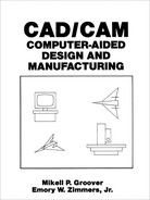
The external appearance of a CNC machine is very similar to that of a conventional NC machine. Part programs are initially entered in a similar manner. Punched tape readers are still the common device to input the part program into the system. However, with conventional numerical control, the punched tape is cycled through the reader for every workpiece in the batch. With CNC, the program is entered once and then stored in the computer memory. Thus the tape reader is used only for the original loading of the part program and data. Compared to regular NC, CNC offers additional flexibility and computational capability. New system options can be incorporated into the CNC controller simply by reprogramming the unit. Because of this reprogramming capacity, both in terms of part programs and system control options, CNC is often referred to by the term “soft-wired” NC. Figure 9.1 illustrates the general configuration of a CNC system.
Figure 9.1 General configuration of computer numerical control (CNC) system.
Functions of CNC
There are a number of functions which CNC is designed to perform. Several of these functions would be either impossible or very difficult to accomplish with conventional NC. The principal functions of CNC are:
1. Machine tool control
2. In-process compensation
3. Improved programming and operating features
4. Diagnostics
MACHINE TOOL CONTROL. The primary function of the CNC system is control of the machine tool. This involves conversion of the part program instructions into machine tool motions through the computer interface and servosystem. The capability to conveniently incorporate a variety of control features into the soft-wired controller unit is the main advantage of CNC. Some of the control functions, such as circular interpolation, can be accomplished more efficiently with hardwired circuits than with the computer. This fact has lead to the development of two alternative controller designs in CNC:
1. Hybrid CNC
2. Straight CNC
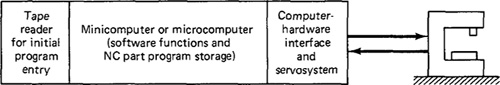
In the hybrid CNC system, illustrated in the diagram of Figure 9.2, the controller consists of the soft-wired computer plus hard-wired logic circuits. The hard-wired components perform those functions which they do best, such as feed rate generation and circular interpolation. The computer performs the remaining control functions plus other duties not normally associated with a conventional hard-wired controller. There are several reasons for the popularity of the hybrid CNC configuration. As mentioned previously, certain NC functions can be performed more efficiently with the hard-wired circuits. These are functions which are common to
Figure 9.2 Hybrid CNC.
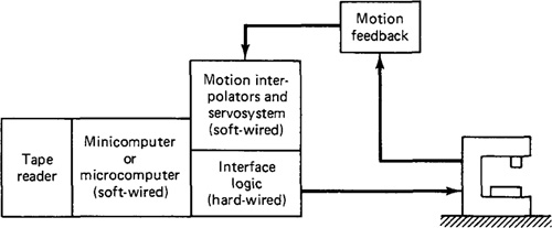
Figure 9.3 Straight CMC.
most NC systems. Therefore, the circuits that perform these functions can be produced in large quantities at relatively low cost. Use of these hard-wired circuits saves the computer from performing these calculation chores. Hence a less expensive computer is required in the hybrid CNC controller.
The straight CNC system uses a computer to perform all the NC functions. The only hard-wired elements are those required to interface the computer with the machine tool and the operator’s console. Interpolation, tool position feedback, and all other functions are performed by computer software. Accordingly, the computer required in a straight CNC system must be more powerful than that needed for a hybrid system. The advantage gained in the straight CNC configuration is additional flexibility. It is possible to make changes in the interpolation programs, whereas the logic contained in the hard-wired circuits of hybrid CNC cannot be altered. A diagram of the straight CNC design is shown in Figure 9.3.
IN-PROCESS COMPENSATION. A function closely related to machine tool control is in-process compensation. This involves the dynamic correction of the machine tool motions for changes or errors which occur during processing. Some of the options included within the category of CNC in-process compensation are:
Adjustments for errors sensed by in-process inspection probes and gauges.
(These are discussed in Section 9.8)
Recomputation of axis positions when an inspection probe is used to locate a datum reference on a workpart.
Offset adjustments for tool radius and length.
Adaptive control adjustments to speed and/or feed. (We consider adaptive control machining in Section 9.7.)
Computation of predicted tool life and selection of alternative tooling when indicated.
IMPROVED PROGRAMMING AND OPERATING FEATURES. The flexibility of soft-wired control has permitted the introduction of many convenient programming and operating features. Included among these features are the following:
Editing of part programs at the machine. This permits correction or optimization of the program.
Graphic display of the tool path to verify the tape.
Various types of interpolation: circular, parabolic, and cubic interpolation.
Support of both U.S. customary units and metric units (International System).
Use of specially written subroutines.
Manual data input (MDI).
Local storage of more than one part program.
DIAGNOSTICS. NC machine tools are complex and expensive systems. The complexity increases the risk of component failures which lead to system downtime. It also requires that the maintenance personnel be trained to a higher level of proficiency in order to make repairs. The higher cost of NC provides a motivation to avoid downtime as much as possible. CNC machines are often equipped with a diagnostics capability to assist in maintaining and repairing the system. These diagnostics features are still undergoing development and future systems will be much more powerful in their capabilities than current CNC units. Ideally, the diagnostics subsystem would accomplish several functions. First, the subsystem would be able to identify the reason for a downtime occurrence so that the maintenance personnel could make repairs more quickly. Second, the diagnostics subsystem would be alert to signs that indicate the imminent failure of a certain component. Hence maintenance personnel could replace the faulty component during a scheduled downtime, thus avoiding an unplanned interruption of production. A third possible function which goes beyond the normal diagnostics capability is for the CNC system to contain a certain amount of redundancy of components which are considered unreliable. When one of these components fails, the diagnostics subsystem would automatically disconnect the faulty component and activate the redundant component. Repairs could thus be accomplished without any breaks in normal operations.
Advantages of CNC
Computer numerical control possesses a number of inherent advantages over conventional NC. The following list of benefits will serve also as a summary of our preceding discussion:
1. The part program tape and tape reader are used only once to enter the program into computer memory. This results in improved reliability, since the tape reader is commonly considered the least reliable component of a conventional NC system.
2. Tape editing at the machine site. The NC tape can be corrected and even optimized (e.g., tool path, speeds, and feeds) during tape tryout at the site of the machine tool.
3. Metric conversion. CNC can accommodate conversion of tapes prepared in units of inches into the International System of units.
4. Greater flexibility. One of the more significant advantages of CNC over conventional NC is its flexibility. This flexibility provides the opportunity to introduce new control options (e.g., new interpolation schemes) with relative ease at low cost. The risk of obsolescence of the CNC system is thereby reduced.
5. User-written programs. One of the possibilities not originally anticipated for CNC was the generation of specialized programs by the user. These programs generally take the form of MACRO subroutines stored in CNC memory which can be called by the part program to execute frequently used cutting sequences.
6. Total manufacturing system. CNC is more compatible with the use of a computerized factory-wide manufacturing system. One of the stepping stones toward such a system is the concept of direct numerical control.
9.5 Direct Numerical Control
Direct numerical control can be defined as a manufacturing system in which a number of machines are controlled by a computer through direct connection and in real time. The tape reader is omitted in DNC, thus relieving the system of its least reliable component. Instead of using the tape reader, the part program is transmitted to the machine tool directly from the computer memory. In principle, one large computer can be used to control more than 100 separate machines. The DNC computer is designed to provide instructions to each machine tool on demand. When the machine needs control commands, they are communicated to it immediately. DNC also involves data collection and processing from the machine tool back to the computer.
Components of a DNC system
Figure 9.4 illustrates the configuration of the basic DNC system. A direct numerical control system consists of four basic components:
1. Central computer
2. Bulk memory, which stores the NC part programs
3. Telecommunication lines
4. Machine tools
The computer calls the part program instructions from bulk storage and sends them to the individual machines as the need arises. It also receives data back from the
Figure 9.4 General configuration of direct numerical control (DNC) system.
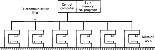
machines. This two-way information flow occurs in real time, which means that each machine’s requests for instructions must be satisfied almost instantaneously. Similarly, the computer must always be ready to receive information from the machines and to respond accordingly. The remarkable feature of the DNC system is that the computer is servicing a large number of separate machine tools, all in real time.
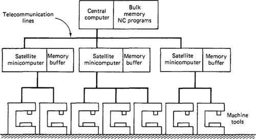
Depending on the number of machines and the computational requirements that are imposed on the computer, it is sometimes necessary to make use of satellite computers, as shown in Figure 9.5. These satellites are minicomputers, and they serve to take some of the burden off the central computer. Each satellite controls several machines. Groups of part program instructions are received from the central computer and stored in buffers. They are then dispensed to the individual machines as required. Feedback data from the machines are also stored in the satellite’s buffer before being collected at the central computer.
Figure 9.5 DNC with satellite minicomputers.
Two types of DNC
There are two alternative system configurations by which the communication link is established between the control computer and the machine tool. One is called a behind-the-tape reader system; the other configuration makes use of a specialized machine control unit.
BEHIND-THE-TAPE-READER (BTR) SYSTEM. In this arrangement, pictured in Figure 9.6, the computer is linked directly to the regular NC controller unit. The replacement of the tape reader by the telecommunication lines to the DNC computer is what gives the BTR configuration its name. The connection with the computer is made between the tape reader and the controller unit—behind the tape reader.
Except for the source of the command instructions, the operation of the system is very similar to conventional NC. The controller unit uses two temporary storage buffers to receive blocks of instructions from the DNC computer and convert them into machine actions. While one buffer is receiving a block of data, the other is providing control instructions to the machine tool.
SPECIAL MACHINE CONTROL UNIT. The other strategy in DNC is to eliminate the regular NC controller altogether and replace it with a special machine control unit. The configuration is illustrated in Figure 9.7. This special MCU is a device that is specifically designed to facilitate communication between the machine tool and the computer. One area where this communication link is important is in circular interpolation of the cutter path. The special MCU configuration
Figure 9.6 DNC with behind-the-tape reader (BTR) configuration.
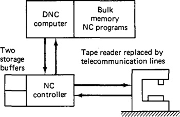
Figure 9.7 DNC with special machine control unit (MCU).
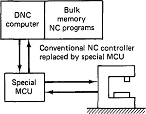
achieves a superior balance between accuracy of the interpolation and fast metal removal rates than is generally possible with the BTR system.
The special MCU is soft-wired, while the conventional NC controller is hard-wired. The advantage of soft-wiring is its flexibility. Its control functions can be altered with relative ease to make improvements. It is much more difficult to make changes in the regular NC controller because rewiring is required.
At present, the advantage of the BTR configuration is that its cost is less, since only minor changes are needed in the conventional NC system to bring DNC into the shop. BTR systems do not require the replacement of the conventional control unit by a special MCU. However, this BTR advantage is a temporary one, since most NC machines are sold with computer numerical control. The CNC controller serves much the same purpose as a special MCU when incorporated into a DNC system.
Functions of DNC
There are several functions which a DNC system is designed to perform. These functions are unique to DNC and could not be accomplished with either conventional NC or CNC. The principal functions of DNC are:
1. NC without punched tape
2. NC part program storage
3. Data collection, processing, and reporting
4. Communications
NC WITHOUT PUNCHED TAPE. One of the original objectives in direct numerical control was to eliminate the use of punched tape. Several of the problems with conventional NC discussed in Section 9.2 are related to the use of punched tape (the relatively unreliable tape reader, the fragile nature of paper tape, the difficulties in making corrections and changes in the program contained on punched tape, etc.). There is also the expense associated with the equipment that produces the punched tape. All of these costs and inconveniences can be eliminated with the DNC approach.
NC PART PROGRAM STORAGE. A second important function of the DNC system is concerned with storing the part programs. The program storage subsystem must be structured to satisfy several purposes. First, the programs must be made available for downloading to the NC machine tools. Second, the subsystem must allow for new programs to be entered, old programs to be deleted, and existing programs to be edited as the need arises. Third, the DNC software must accomplish the postprocessing function. The part programs in a DNC system would typically be stored as the CLFILE. The CLFILE must be converted into instructions for a particular machine tool. This conversion is performed by the postprocessor. Fourth, the storage subsystem must be structured to perform certain data processing and management functions, such as file security, display of programs, manipulation of data, and so on.
The DNC program storage subsystem usually consists of an active storage and a secondary storage. The active storage would be used to store NC programs which are frequently used. A typical mass storage device for this purpose would be a disk. The active storage can be readily accessed by the DNC computer to drive an NC machine in production. The secondary storage would be used for NC programs which are not frequently used. Sometimes, even though it is anticipated that a particular program will probably never be used again, it may be decided to save that program if the storage costs are not excessive. Examples of secondary storage media used in DNC include magnetic tape, tape cassettes, floppy disks, disk packs, and even punched tape. (Unfortunately, the last alternative resurrects the several disadvantages mentioned earlier.)
DATA COLLECTION, PROCESSING, AND REPORTING. The two previous functions for DNC both concerned the direct link from the central computer to the machine tools in the factory. Another important function of DNC involves the opposite link, the transfer of data from the machine tools back to the central computer. DNC involves a two-way transfer of data.
The basic purpose behind the data collection, processing, and reporting function of DNC is to monitor production in the factory. Data are collected on production piece counts, tool usage, machine utilization, and other factors that measure performance in the shop. These data must be processed by the DNC computer, and reports are prepared to provide management with information necessary for running the plant. The scope of this DNC function has been broadened over the years to include data collection not only from the NC machines, but from all other work centers in the factory. The term used to describe this broader scope activity is shop floor control. We shall be discussing shop floor control and computer process monitoring in subsequent chapters of this book.
COMMUNICATIONS. A communications network is required to accomplish the previous three functions of DNC. Communication among the various subsystems is a function that is central to the operation of any DNC system. The essential communication links in direct numerical control are between the following components of the system:
Central computer and machine tools
Central computer and NC part programmer terminals
Central computer and bulk memory, which stores the NC programs
Optional communication links may also be established between the DNC system and any of the following additional systems:
Computer-aided design (CAD) system
Shop floor control system
Corporate data processing computer
Remote maintenance diagnostics system
Other computer-automated systems in the plant
These types of communications are becoming more common as DNC technology moves toward the computer-integrated factory of the future.
Advantages of DNC
Just as CNC had certain advantages over a conventional NC system, there are also advantages associated with the use of direct numerical control. The following list will recapitulate much of our previous discussion of DNC:
1. Elimination of punched tapes and tape readers. Direct numerical control eliminates the least reliable element in the conventional NC system. In some DNC systems, the hard-wired control unit is also eliminated, and replaced by a special machine control unit designed to be more compatible with DNC operation.
2. Greater computational capability and flexibility. The large DNC computer provides the opportunity to perform the computational and data processing functions more effectively than traditional NC. Because these functions are implemented with software rather than with hard-wired devices, there exists the flexibility to alter and improve the method by which these functions are carried out. Examples of these functions include circular interpolation and part programming packages with convenient editing and diagnostics features.
3. Convenient storage of NC part programs in computer files. This compares with the more manually oriented storage of punched tapes in conventional NC.
4. Programs stored as CLFILE. Storage of part programs in DNC is generally in the form of cutter path data rather than postprocessed programs for specific machine tools. Storing of the programs in this more general format affords the flexibility in production scheduling to process a job on any of several different machine tools.
5. Reporting of shop performance. One of the important features in DNC involves the collection, processing, and reporting of production performance data from the NC machines.
6. Establishes the framework for the evolution of the future computer-automated factory. The direct numerical control concept represents a first step in the development of production plants which will be managed by computer systems.
9.6 Combined DNC/CNC Systems
The direct numerical control systems that were marketed in the late 1960s and early 1970s were extremely expensive. Their high cost, combined with an unfavorable economic climate at that time, caused business managers to resist the temptation to plunge into the new DNC technology. Also, the DNC systems available then were somewhat rigid in terms of management reporting formats and hardware requirements. The advent of CNC systems, together with lower-cost computers and improvements in software, have resulted in the development of hierarchical computer systems in manufacturing. In these hierarchical systems, CNC computers have direct control over the production machines and report to satellite minicomputers, which in turn report to other computers, and so on. There are advantages to this hierarchical approach over the DNC packages that were offered around 1970. The common theme in these advantages is flexibility. The information system can be tailored to the specific needs and desires of the firm. This contrasts with many of the early DNC systems, in which the reporting formats were fixed, in some cases providing more data than management wanted and in other cases omitting details that management needed. Another advantage of the hierarchy approach is the ability to gradually build the system instead of implementing the entire DNC configuration all at once. This piece-by-piece installation of the computer-integrated manufacturing system is a more versatile and economic approach. It permits changes and corrections to be made more easily as the system is being built. It also allows the company to spread the cost of the system over a longer time period and to obtain benefits from each subsystem as it is installed. The hierarchical computer arrangement embraces the DNC philosophy, which is to provide useful reports on production operations to management in real time. One might say that DNC has not really been replaced by this new approach; it has simply altered its physical form. This evolution in the configuration of DNC and its inclusion of computer numerical control have resulted in the introduction of the term “distributed numerical control” for the initials DNC.
The combination of DNC and CNC provides the opportunity to add new capabilities and refine existing capabilities in these computerized manufacturing systems. Certainly, an obvious advantage derived from the combination of CNC and DNC is the elimination of the use of punched tape as the input media for CNC machines. The DNC computer downloads the program directly to the CNC computer memory. Unlike the machine control unit in a conventional DNC system, the CNC controller has sufficient storage capacity to accept the entire part program. The part program is downloaded once rather than in a block-by-block procedure. This reduces the amount of communication required between the central computer and each machine tool. A likely future trend in these combined DNC/CNC systems will be that the postprocessor is built into the software of the CNC controller. This would allow the part program to be downloaded from the DNC computer in CLFILE form without postprocessing.
A second advantage created by combining CNC with DNC is redundancy. If the central DNC computer fails, this will not necessarily cause the individual machines in the system to be down. It is possible to provide the necessary backup to permit the CNC machines to operate on a stand-alone basis. This backup capability consists of two elements. The first is a file of punched tapes which duplicate the programs contained in the DNC computer files. The second is that each CNC machine must be equipped with a tape reader or be capable of connecting to a portable tape reader for the purpose of entering the program from the punched tape. There are, of course, costs associated with providing this backup feature.
A third improvement that develops from combined DNC/CNC systems is improved communication between the central computer and the shop floor. With digital computers located at both ends of the communication links, many of the constraints in the design of powerful factory management information systems are removed. It is easier for computers to communicate with other computers than with hard-wired devices.
9.7 Adaptive Control Machining Systems
Adaptive control (abbreviated AC) machining originated out of research in the early 1960s sponsored by the U.S. Air Force at the Bendix Research Laboratories. The initial adaptive control systems were based on analog control devices, representing the state of technology at that time. Today, AC uses microprocessor-based controls and it is typically integrated with an existing CNC system. Accordingly, the topic of adaptive control is appropriate to include in this chapter on computer controls in NC.
For a machining operation, the term adaptive control denotes a control system that measures certain output process variables and uses these to control speed and/or feed. Some of the process variables that have been used in adaptive control machining systems include spindle deflection or force, torque, cutting temperature, vibration amplitude, and horsepower. In other words, nearly all the metal-cutting variables that can be measured have been tried in experimental adaptive control systems. The motivation for developing an adaptive machining system lies in trying to operate the process more efficiently. The typical measures of performance in machining have been metal removal rate and cost per volume of metal removed.
Where to use adaptive control
One of the principal reasons for using numerical control (including DNC and CNC) is that NC reduces the nonproductive time in a machining operation. This time savings is achieved by reducing such elements as workpiece handling time, setup of the job, tool changes, and other sources of operator and machine delay. Because these nonproductive elements are reduced relative to total production time, a larger proportion of the time is spent in actually machining the workpart. Although NC has a significant effect on downtime, it can do relatively little to reduce the in-process time compared to a conventional machine tool. The most promising answer for reducing the in-process time lies in the use of adaptive control. Whereas numerical control guides the sequence of tool positions or the path of the tool during machining, adaptive control determines the proper speeds and/or feeds during machining as a function of variations in such factors as work-material hardness, width or depth of cut, air gaps in the part geometry, and so on. Adaptive control has the capability to respond to and compensate for these variations during the process. Numerical control does not have this capability.
Adaptive control (AC) is not appropriate for every machining situation. In general, the following characteristics can be used to identify situations where adaptive control can be beneficially applied:
1. The in-process time consumes a significant portion of the machining cycle time. Mathias [12] uses the rule of thumb that adaptive control can best be justified when the cutter is engaged in the workpiece more than 40% of the time it is on the machine.
2. There are significant sources of variability in the job for which adaptive control can compensate. In effect, AC adapts feed and/or speed to these variable conditions. We examine these sources of variability in the following subsection.
3. The cost of operating the machine tool is high. The high operational cost results mainly from the high investment in equipment.
4. The typical jobs are ones involving steel, titanium, and high-strength alloys. Cast iron and aluminum are also attractive candidates for AC, but these materials are generally easier to machine.
Sources of variability in machining
The following are the typical sources of variability in machining where adaptive control can be most advantageously applied. Not all of these sources of variability need be present to justify the use of AC. However, it follows that the greater the variability, the more suitable the process will be for using adaptive control.
1. Variable geometry of cut in the form of changing depth or width of cut. In these cases, feed rate is usually adjusted to compensate for the variability. This type of variability is often encountered in profile milling or contouring operations.
2. Variable workpiece hardness and variable machinability. When hard spots or other areas of difficulty are encountered in the workpiece, either speed or feed is reduced to avoid premature failure of the tool.
3. Variable workpiece rigidity. If the workpiece deflects as a result of insufficient rigidity in the setup, the feed rate must be reduced to maintain accuracy in the process.
4. Toolwear. It has been observed in research that as the tool begins to dull, the cutting forces increase. The adaptive controller will typically respond to tool dulling by reducing the feed rate.
5. Air gaps during cutting. The workpiece geometry may contain shaped sections where no machining needs to be performed. If the tool were to continue feeding through these so-called air gaps at the same rate, time would be lost. Accordingly, the typical procedure is to increase the feed rate by a factor or 2 or 3, when air gaps are encountered.
These sources of variability present themselves as time varying and, for the most part, unpredictable changes in the machining process. We shall now examine how adaptive control can be used to compensate for these changes.
Two types of adaptive control
In the development of adaptive control machining systems, two distinct approaches to the problem can be distinguished. These are:
1. Adaptive control optimization (ACO)
2. Adaptive control constraint (ACC)
ADAPTIVE CONTROL OPTIMIZATION. This is represented by the early Bendix research on adaptive control machining. In this form of adaptive control, an index of performance is specified for the system. This performance index is a measure of overall process performance, such as production rate or cost per volume of metal removed. The objective of the adaptive controller is to optimize the index of performance by manipulating speed and/or feed in the operation.
Most adaptive control optimization systems attempt to maximize the ratio of work material removal rate to tool wear rate. In other words, the index of performance is
![]()
where MRR = material removal rate
TWR = tool wear rate
The trouble with this performance index is that TWR cannot be measured on-line with today’s measurement technology. Hence the IP above cannot really be monitored during the process. Eventually, sensors will be developed to a level at which the true process performance can be measured on-line. When this occurs, adaptive control optimization systems will become more prominent. However, because of the sensor problems encountered in the design of ACO systems, nearly all adaptive control machining is of the second type, adaptive control constraint systems.
ADAPTIVE CONTROL CONSTRAINT. The systems developed for actual production were somewhat less sophisticated (and less expensive) than the research ACO systems. The production AC systems utilize constraint limits imposed on certain measured process variables. Accordingly, these are called adaptive control constraint (ACC) systems. The objective in these systems is to manipulate feed and/or speed so that these measured process variables are maintained at or below their constraint limit values. The following subsection describes the operation of the most common commercially available ACC system.
Operation of an ACC System
Typical applications of adaptive control machining are in profile or contour milling jobs on an NC machine tool. Feed is used as the controlled variable, and cutter force and horsepower are used as the measured variables. It is common to attach an adaptive controller to an NC machine tool. Numerical control machines are a natural starting point for AC for two reasons. First, NC machine tools often possess the required servomotors on the table axes to accept automatic control. Second, the usual kinds of machining jobs for which NC is used possess the sources of variability that make AC feasible. Several large companies have retrofitted their NC machines to include adaptive control. One company, Macotech Corporation in Seattle, Washington, specializes in retrofitting NC machine tools for other manufacturing firms. The adaptive control retrofit package consists of a combination of hardware and software components. The typical hardware components are:
1. Sensors mounted on the spindle to measure cutter deflection (force).
2. Sensors to measure spindle motor current. This is used to provide an indication of power consumption.
3. Control unit and display panel to operate the system.
4. Interface hardware to connect the AC system to the existing NC or CNC control unit.
The software in the AC package consists of a machinability program which can be called as an APT MACRO statement. The relationship of the machinability program in the part programming process is shown in Figure 9.8. The inputs to the program include cutting parameters such as cutter size and geometry, work material hardness, size of cut, and machine tool characteristics. From calculations
Figure 9.8 Relationship of adaptive control (AC) software to APT program.
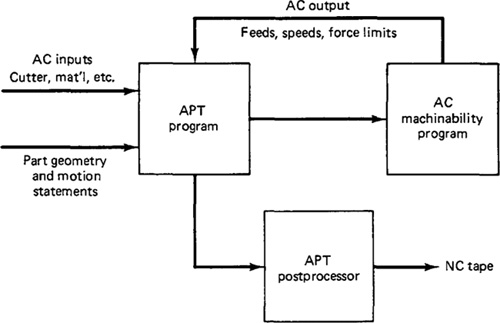
based on these parameters, the outputs from the program are feed rates, spindle speeds, and cutter force limits for each section of the cut. The objective in these computations is to determine cutting conditions which will maximize metal removal rates. The NC part programmer would ordinarily have to specify feeds and speeds for the machining job. With adaptive control, these conditions are computed by the machinability program based on the input data supplied by the part programmer.
In machining, the AC system operates at the force value calculated for the particular cutter and machine tool spindle. Maximum production rates are obtained by running the machine at the highest feed rate consistent with this force level. Since force is dependent on such factors as depth and width of cut, the end result of the control action is to maximize metal removal rates within the limitations imposed by existing cutting conditions.
Figure 9.9 shows a schematic diagram illustrating the operation of the AC system during the machining process. When the force increases due to increased workpiece hardness or depth or width of cut, the feed rate is reduced to compensate. When the force decreases, owing to decreases in the foregoing variables or air gaps in the part, feed rate is increased to maximize the rate of metal removal.
Figure 9.9 shows an air-gap override feature which monitors the cutter force and determines if the cutter is moving through air or through metal. This is usually sensed by means of a low threshold value of cutter force. If the actual cutter force is below this threshold level, the controller assumes that the cutter is passing through an air gap. When an air gap is sensed, the feed rate is doubled or tripled to minimize the time wasted traveling across the air gap. When the cutter reengages metal on the other side of the gap, the feed reverts back to the cutter force mode of control.
Figure 9.9 Configuration of typical adaptive control machining system that uses cutter forces as the measured process variable.

More than one process variable may be measured in an adaptive control machining system. Originally, attempts were made to employ three measured signals in the Bendix system: temperature, torque, and vibration. Currently, the Macotech system has used both cutter load and horsepower generated at the machine motor. The purpose of the power sensor is to protect the motor from overload when the metal removal rate is constrained by spindle hoursepower rather than spindle force.
Benefits of adaptive control machining
A number of potential benefits accrue to the user of an adaptive control machine tool. The advantage gained will depend on the particular job under consideration. There are obviously many machining situations for which it cannot be justified. Adaptive control has been successfully applied in such machining processes as milling, drilling, tapping, grinding, and boring. It has also been applied in turning, but with only limited success. Following are some of the benefits gained from adaptive control in the successful applications.
1. Increased production rates. Productivity improvement was the motivating force behind the development of adpative control machining. On-line adjustments to allow for variations in work geometry, material, and tool wear provide the machine with the capability to achieve the highest metal removal rates that are consistent with existing cutting conditions. This capability translates into more parts per hour. Given the right application, adaptive control will yield significant gains in production rate compared to conventional machining or numerical control. The production rate advantage of adaptive control over NC machining is illustrated in Table 9.1 for milling and drilling operations on a variety of work materials. Savings in cycle time reported in this table range from 20% up to nearly 60% for milling and 33 to 38% for drilling.
2. Increased tool life. In addition to higher production rates, adaptive control will generally provide a more efficient and uniform use of the cutter throughout its tool life. Because adjustments are made in the feed rate to prevent severe loading of the tool, fewer cutters will be broken.
3. Greater part protection. Instead of setting the cutter force constraint limit on the basis of maximum allowable cutter and spindle deflection, the force limit can be established on the basis of work size tolerance. In this way, the part is protected against an out-of-tolerance condition and possible damage.
4. Less operator intervention. The advent of adaptive control machining has transferred control over the process even further out of the hands of the machine operator and into the hands of management via the part programmer.
Table 9.1 Comparison of Machining Times—NC versus Adaptive Control
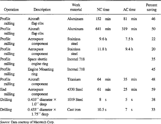
Source: Data courtesy of Macotech Corp.
5. Easier part programming. A benefit of adaptive control which is not so obvious concerns the task of part programming. With ordinary numerical control, the programmer must plan the speed and feed for the worst conditions that the cutter will encounter. The program may have to be tried out several times before the programmer is satisfied with the choice of conditions. In adaptive control part programming, the selection of feed is left to the controller unit rather than to the part programmer. The programmer can afford to take a less conservative approach than with conventional NC programming. Less time is needed to generate the program for the job, and fewer tryouts are required.
9.8 Trends and New Developments in NC
We will conclude these three chapters on numerical control by discussing some of the important trends and new developments in NC technology. Without question, the most important general trend in NC involves the expanding use of computer technology. The use of computers has already provided significant improvements in part programming procedures (e.g., computer-assisted programming, interactive graphics, and voice programming). The control of NC machinery has also been dramatically enhanced through computer technology (e.g., CNC, DNC, and adaptive control). We have covered these topics in Chapter 8 on programming and in the current chapter on computerized NC. In the following sections, we discuss some additional topics likely to influence the future evolution of numerical control.
Replacement of punched tape
The standard medium used to contain the part program in NC has been l-in.-wide punched tape. As already discussed there are problems with the use of this medium. With the greater use of computers in today’s numerically controlled processes, there is a movement among machine builders and controls people to replace the punched tape and tape reader with a medium that is more compatible with modern computer systems. The most likely substitute is a magnetic tape cartridge. Because of the large inventory of punched tapes and associated equipment in industry presently, the transition to a new part program medium will take a long time.
Inspection probes
The use of in-process inspection probes is becoming more common in modern NC machine tool systems. These inspection probes are sophisticated dial indicators which can be mounted in the machine tool spindle. In machines with automatic tool changers, the probe would be placed in the tool storage drum and loaded into the spindle when needed, just like any of the regular cutting tools. Sensors in the probe detect when contact has been made with a surface of the workpart (or other
Figure 9.10 Inspection probe used in NC machine tools. (Courtesy of Kearney ' Trecker Corp.)
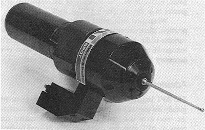
object) being checked. The sensor signals are transmitted inductively to the machine tool, thus avoiding the need for supplementary direct wiring between the inspection probe and the NC computer control unit. The software in the controller performs the necessary computations to interpret the signals from the probe. One of the commercially available inspection probes is illustrated in Figure 9.10.
Some typical applications of the inspection probes include the following:
In-process inspection of parts while still fixtured on the machine table Self-correction of tool locations to compensate for machine errors Location of a datum reference on the part after initial machining to achieve greater accuracy in subsequent machining operations Inspection of cutting tools to determine the condition of the cutter (e.g., broken teeth on cutter)
The prinicpal benefits that derive from the use of inspection probes are time savings and improved accuracy. Time can be saved in several activities during part production. The most obvious of these is reducing the need for the time-consuming manual inspection procedures which normally follow the machining operations. As in-process inspection techniques are perfected, this tedious human activitiy will be substantially decreased. Other time savings result from a reduction in the setup and alignment of parts on the machine table (the probe is used to determine compensations for part location errors), and savings in remachining time (in-process inspection is performed with the probe while the job is still set up on the machine). Improved accuracy in the measurement process results from the inherent accuracy in the rigid machine tool structure. Measurements taken with the spindle probe are generally more accurate than traditional techniques used to measure part dimensions. Furthermore, the accuracy of the inspection probe system is substantially greater than the machining process itself.
When used for in-process measurement with resulting compensations in cutter position, these inspection probes represent a form of adaptive control. The process variable is the deviation from specified part dimension caused by cutter wear, fixture problems, or other errors. To correct for these errors, the system makes the necessary adjustments in the calculated tool path.
Advanced NC systems
The APT language for NC part programming is more than 20 years old. It was originally developed for the milling process and has been modified and enhanced over the years to be compatible with other manufacturing operations. Many of the concepts of APT geometry definition were utilized to develop the current geometric modeling technology of CAD/CAM. In many respects, developments in computerized geometric modeling have outpaced and outdated the APT geometry concepts. Advanced NC systems would attempt to make use of the latest CAD/CAM geometry concepts and not be constrained by the limitations inherent in APT. One of the important research and development efforts in this area is CAM-I’s1 Advanced NC Project. The objectives are to develop an advanced NC system that would use the latest concepts and technologies in CAD/CAM and data base management. It is beyond the scope and purpose of this book to provide a lengthy discussion of this R'D project. The interested reader should consult the latest project reports published by CAM-I[3]. However, it seems appropriate to give a summary of this important project.
1 CAM-I stands for Computer-Aided Manufacturing—International, a nonprofit firm based in Arlington, Texas.
In APT programming, the workpart is defined with geometric elements such as lines, planes, and circles. These lines, planes, and circles are “unbounded” in the sense that the lines and planes are infinite and the circles are complete circles. The workpart, of course, is bounded, so the APT geometry elements do not really provide an accurate and comprehensive definition of the part geometry. It is by means of a sequence of APT motion statements that the tool is directed around the actual surface of the part, ignoring the portions of the circles and lines that do not relate to the part. In the CAD/CAM approach to geometric modeling, the part is defined by surfaces and edges that construct a solid geometric description of the part. The surfaces and edges do not extend infinitely in their respective directions. The term given to this method of part definiton is “bounded geometry,” which contrasts with the unbounded approach used in APT. One of the important goals of CAM-I’s advanced NC project is to utilize the concepts embodied in the bounded geometry approach to part definition. Some of the important objectives of the project can be outlined as follows:
1. New language set. The objective is to develop a new language set which would use the concepts of bounded geometry. An attempt will be made to make the new language set compatible with the APT language. The new language would be a higher level than APT.
2. Multiple applications. The advanced NC system would not be restricted to machining operations but would be suitable for many non-machining applications, such as inspection and pressworking (shearing and forming operations).
3. Modular design. To facilitate the multiple applications, the advanced NC system would possess a modular design. Separate processors or subroutines would be designed to accomplish the basic functions, such as profiling, pocketing, point-to-point operations, turning, inspection, and so forth. This approach is similar to the one used in modern CAD/CAM part programming packages, where automatic routines have been designed to accomplish special functions.
4. Automation of NC programming function. NC programming includes, in addition to generation of the tool path, tool selection, feed, and speed selection, sequencing of operations, and other details. Advanced NC systems would automate the determination of these parameters.
5. Interference checking. Subroutines would be built into the advanced NC programming packages to check for possible collision between the tool and fixtures holding the part, as well as other potential interference problems.
6. Interface with CAD/CAM data base. The advanced numerical control sytems would be interfaced with a common design and manufacturing data base. The data base would contain data relating to the part geometry (raw stock and finished part dimensions), fixtures, machine tools, available tooling, and cost data. The NC programming function would be interfaced with the more general computer-automated process planning packages. We will be covering the various automated process planning procedures in a subsequent chapter.
Flexible manufacturing systems
One of the important developments in DNC was the introduction of the flexible manufacturing sytem (FMS). An FMS is a group of NC machines (or other automated workstations) which are interconnected by a materials handling system. All of the machines and the work handling system are controlled by computer. Flexible manufacturing systems were first introduced around 1970. Owing to the very high cost of these systems (several million dollars per FMS), there were only about a dozen of these systems installed by the end of 1980. However, the FMS offers such a high potential for productivity improvement in batch manufacturing that the number of installations is expected to grow substantially during the 1980s. The FMS represents an important step in the evolution of the computer-automated factory of the future, and we will examine these systems in Chapter 20.
Robotics
In terms of control technology and programming, industrial robots share much in common with numerical control machines. Robots are used for moving workparts and tools in the performance of industrial tasks. An important number of these tasks are concerned with the loading and unloading of production machines, including NC machines. The robot and the machine form an automatic work cell, with raw workparts being fed into the cell by conveyor and completed parts leaving the cell by conveyor. All this is accomplished with little or no human attention. Because robotics constitutes such an important CAD/CAM topic, we devote the next major part of this book (two chapters) to the subject of industrial robots.
References
[1] BEERCHECK, R.C., “Machine Tools: Cutting Edge of Technology,” Machine Design, January 25, 1979, pp. 18–47.
[2] CAMPBELL, F. S., “Adaptive Control at McAir,” CAM Directions (McDonnell Douglas), October, 1977.
[3] COMPUTER-AIDED MANUFACTURING-INTERNATIONAL, Inc., CAM-/Advanced NIC Project, PR-81-ASPP-D1.4, Arlington, Tex., 1982.
[4] DIRKSON, G. F., “CNC and DNC—The Marriage,” Proceedings, Eighteenth Annual Meeting and Technical Conference, Numerical Control Society, Dallas, Tex., May, 1981, pp. 132–138.
[5] FOLKMAN, J., “DNC, What Is It?” Tooling and Production, January, 1982, pp. 70–73.
[6] GROOVER, M. P., “Adaptive Control and Adaptive Control Machining,” Educational Module, Manufacturing Productivity Educational Committee, Purdue Research Foundation, West Lafayette, Ind., 1977.
[7] GROOVER, M. P., Automation, Production Systems, and Computer-Aided Manufacturing, Prentice-Hall, Inc., Englewood Cliffs, N. J., 1980, Chapter 9.
[8] HATSCHEK, R. L., “NC Diagnostics,” Special Report 744, American Machinist, April, 1982, pp. 161–168.
[9] HEGLAND, D. E., “Numerical Control—Your Best Investment in Productivity,” Production Engineering, March, 1981, pp. 42–47.
[10] “Manufacturing Turns to Technology,” American Machinist, January, 1981, pp. 101–108.
[11] MATHIAS, R. A., “Adaptive Control for the Eighties,” Paper MS80-242, Society of Manufacturing Engineers, Dearborn, Mich., 1980.
[12] MATHIAS, R. A., “Determining Where Adaptive Control Can Most Benefit Your Machining Operations,” Paper MS81-272, Society of Manufacturing Engineers, Dearborn, Mich., 1981.
[13] MATHIAS, R. A., “Adaptive Control, Key to Productivity,” paper presented at the Conference on Computer Aided Manufacturing and Productivity, London, October, 1981.
[14] MURRAY, D., “CAM-I’s Advanced Numerical Control Project Update,” Commline, March/April, 1980, p. 40.
[15] PRESSMAN, R. S., AND WILLIAMS, J. E., Numerical Control and Computer-Aided Manufacturing, John Wiley ' Sons, Inc., New York, 1977, Chapter 10.
[16] SMITH, D. N., AND EVANS, L., Management Standards for Computer and Numerical Controls, University of Michigan, Ann Arbor, 1977.