
Terms you need to understand:
Techniques you need to master:
|
|
|
|
|
Understand how the telephone components interact for initiating and answering calls |
|
|
Understand the operation of loop start, ground start, and E&M circuits |
|
|
Understand Answer and Disconnect Supervision |
|
|
Understand the E&M signaling, types, and usage |
|
|
Understand the three types of start types: Wink Start, Immediate Start, and Delay Dial Supervision |
Even with the growth of IP telephony in the enterprise network, many analog devices, including phones and facsimile (fax) machines, are still being used today. Therefore, you should understand how analog devices function and connect to the network through routers and gateways, as well as to the central office (CO).
This chapter focuses on the phone. You must understand the components of the phone to know how they interact to initiate and receive calls. Three types of circuits connect phones and trunk lines: loop start, ground start, and E&M. The type of circuit you choose depends on whether you are connecting to a phone, a private branch exchange (PBX), or another type of device. Each of these circuits has its purpose, which you explore in this chapter.
We begin with the various components of the analog phone, similar to the one you have in your home. The handset is composed of two components: the receiver (within the earpiece) and the transmitter (within the mouthpiece). These two components supply the phone with four wires for the communication path (two wires each from the receiver and transmitter). However, the CO expects only two wires (tip and ring) on most residential circuits. So, how do you convert the four wires from the receiver and transmitter to two wires (tip and ring)? The answer is a 2-wire–to–4-wire hybrid circuit within the phone that provides this conversion.
Note
Tip and ring are common terms in the telephone service industry that refer to the two wires or sides of an ordinary telephone line. Tip is the ground side (positive) and ring is the battery (negative) side of a phone circuit. The terms came about in the early days when all calls went through a manual switchboard with plugs.
Now we’re ready to make the call. The switch hook component of the phone enables the phone to signal when a call is ready to begin. The CO detects when the handset is off-hook or on-hook. The phone going off-hook causes a contact closure, joining the ring and tip wires connected to the CO. This action completes the circuit, and –48vDC is available from the CO, causing the current flow through the tip and ring. The CO detects this flow of current and provides the phone with dial tone.
Exam Alert
The CO is responsible for detecting when the user has lifted the receiver from the phone, which creates the off-hook or closed-circuit condition using a manual relay in the phone. You should watch this on the exam because it is easy to think that the handset creates the off-hook condition, which is not correct; it is the switch hook (relay) in the phone.
At this point, the user can make a call using the dialer. The dialer produces dual tone multifrequency (DTMF) signaling to the CO for each digit the caller selects. These frequencies are recognized and interpreted as the proper digits at the CO to complete the call to the desired location. The DTMF signals are a combination of two tones (dual tone) produced by each digit at different frequencies (multifrequency), as shown in Table 2.1.

For an incoming call, the CO signals the phone by applying an AC ring voltage, which activates the ringer in the phone. At this point, the called party answers the phone by lifting the handset, which causes the switch hook to create a contact closure between the ring and tip. This off-hook condition signals to the CO to stop the ring voltage. The communication path is now complete, and the conversation can proceed.
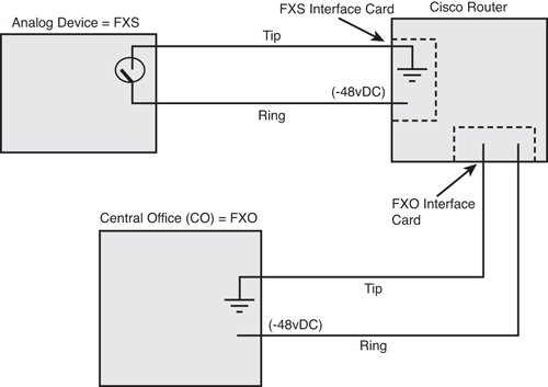
To connect an analog device or telephone line to an IP network, an interface card is needed in a Cisco router. This interface comes in two different types: the Foreign Exchange Station (FXS) and the Foreign Exchange Office (FXO).
The FXS interface card is used to connect phones, fax machines, modems, and other types of “station” devices. The FXS interface card is responsible for producing the voltage and dial tone upon switch hook signaling from the attached device, as well as ring voltage for an incoming call. When the user goes off-hook, the FXS interface card supplies proper voltage to the phone so that the caller can use the dialer to complete the call. In essence, the FXS interface simulates what the CO does for residential circuits.
Note
The FXS component is defined as the device that connects to the FXS interface card on a Cisco router. This device can be an analog phone, modem, fax, or similar type of device.
When the call setup is complete and you have established a two-way communication path, the FXS interface continues to supply power to the phone for the operation of the receiver and transmitter. The communication from the phone to the FXS interface is entirely analog. However, communication within the router and the IP network is digital. Therefore, you must convert this analog signal to digital for communication through the network. The FXS interface provides a component called a digital signal processor (DSP) that is programmed to operate based on codec definitions. The purpose of the DSP/codec combination is to sample the analog signal, convert it to a digital format, and convert from digital to analog communication in the reverse direction. The term codec is derived from the words code and decode.
The FXO interface card is used to provide a connection to the network for the CO trunk line. This type of interface terminates the connection from the CO by answering incoming calls and providing access for outgoing calls. Depending on the configuration, the FXO interface card can supply another dial tone (an outside dial tone), or it can make a call directly to a preconfigured number, referred to as a PLAR (private line, automatic ringdown). PLAR circuits are commonly used for security phones or unattended lobby phones, where the phone automatically dials a predefined number when an off-hook condition occurs. This is sometimes referred to as the hotline or Batphone (remember the old Batman series and Commissioner Gordon’s phone?).
The FXO interface can also supply signaling for outbound calls in the form of DTMF tones. The older pulse-dial type can be configured, though these are not as prevalent. In the past, however, the most common types of dialers were pulse dial, which was used by rotary-style phones.
You can install both FXS and FXO interface cards in a Cisco router to provide analog connections to the network. In Figure 2.1, a Cisco router is equipped with both FXS and FXO interface cards. Note how they connect with the two-wire analog circuit.
There are three analog circuit types that use different physical and logical methods of connecting and transmitting analog voice signals. These three circuit types are loop start, ground start, and E&M.
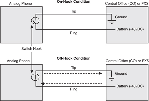
The loop start circuit is the first signaling type that we examine. This is the two-wire circuit that the telephone company provides to your home and what is used in most residential circuits. The concept is easy to understand if you think about how a circuit works. When the phone is on-hook, the circuit is open between the tip and ring. In this “open” condition, current is prevented from flowing.
When the user picks up the handset, the switch hook creates the off-hook condition, and the circuit is now closed. The CO provides –48vDC on the ring lead, which causes current to flow. This is referred to as line seizure because you are literally “seizing” the line. The CO senses this current and provides dial tone to the phone. If the phone is connected to an FXS interface module, the module detects the current and produces the dial tone.
This operation is going to be somewhat different for an incoming call. In this case, you are beginning in the on-hook condition. The CO or FXS interface module signals to the phone that an incoming call is present by applying an AC voltage in addition to the –48vDC signal. The ringer on the phone senses this AC voltage, causing the phone to ring. When the user answers the call, the switch hook again causes the off-hook condition, where current flows. This condition is detected by the CO or FXS interface, where it stops sending the ring voltage. Figure 2.2 defines the on-hook and off-hook conditions of the loop start circuit.
Now that you are familiar with how your home phone works, have you ever noticed a time when you were dialing a friend, and the person picked up the phone and you were connected before hearing it ring? This is a condition called glare. It occurs when there is no mechanism to signal the remote “called” location with an off-hook or on-hook condition. Glare occurs when line seizure occurs at both ends of the circuit at the same time. This is one shortcoming of the traditional loop start line, because neither side is able to detect the line seizure from end to end.
Exam Alert
Glare is the condition when both parties seize the line at the same time. You should remember this for exam time and understand that both Answer and Disconnect Supervision eliminate this condition. Loop start circuits used in residential areas lack this mechanism.
Glare is not a major issue with residential circuits, but it can be a real problem with business and enterprise, high-volume circuits. The solution to the problem is a different type of circuit called ground start.
Ground start circuits ultimately accomplish the same purpose as the loop start circuit, but without the glare issue. For this reason, ground start circuits are used primarily in businesses to connect to FXO interfaces on routers and gateways and to connect directly to a PBX, where an analog connection is needed. However, they are not used to connect directly to the standard analog phone. Although they are not commonly used in IP networks, ground start circuits overcome the glare issue by signaling line seizure to the remote end. They accomplish this by removing or reversing the current on answer and disconnect. This action provides the signaling to the remote end, eliminating glare, which is called Answer and Disconnect Supervision. For these reasons, ground start circuits require a common ground between the originating and terminating ends of the circuit to function properly.
Figure 2.3 illustrates a ground start call procedure on a line connected from an FXO interface card on a Cisco router to the CO.
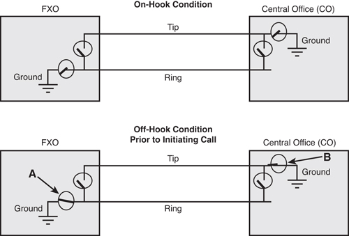
We begin with an FXO interface card that has a two-wire (tip and ring) configured for ground start to the CO. When a call is being made that originates from the IP network (toward the CO), the FXO interface grounds the ring side of the circuit (see A in Figure 2.3). The CO acknowledges this by grounding the tip side of the circuit (see B in Figure 2.3). This action lets the FXO interface know that the CO is ready for the call. Finally, to complete the connection (not shown in Figure 2.3), the FXO interface connects the ring to tip and removes the ground. The line is now seized and the communication path is complete for the conversation to proceed.
Exam Alert
You should remember that ground start circuits are more common in business, high-volume analog applications because they don’t have issues with glare, as do loop start circuits.
For an incoming call to the gateway, the CO signals the call by grounding the tip side and applying a 90 volt AC (20Hz) signal. This is the ring voltage that the FXO interface uses (along with the tip being grounded) to sense the incoming call. If the line is available, the FXO interface (again) connects the ring to tip and removes the ground. This must occur within 100ms, or a reorder tone will be delivered to the caller. This timeout is another mechanism that helps ground start circuits to prevent glare. When the circuit is complete (ring to tip), the CO senses the incoming current and removes the ring voltage. The line seizure is now complete, and the conversation can proceed. This same action applies to a ground start circuit between a PBX and a CO, or a PBX and an FXS interface.
A third type of circuit, the E&M circuit, uses either two-wire or four-wire connections (one transmit pair and one receive pair of wires) for both the voice connection and either an E-lead or M-lead to provide signaling for on-hook and off-hook conditions. The four-wire is the most common type and is used primarily for connection to an E&M router interface card or a PBX. For each end of the circuit in an E&M circuit, one side is called the trunk side (typically a PBX), while the other side is referred to as the signaling-unit side (typically, the CO or an E&M interface on a Cisco router). The trunk side uses the E-lead to signal an off-hook condition, whereas the signaling-unit side uses the M-lead.
The E&M term comes from the words Earth and Magneto, where Earth is the ground and Magneto is the electromagnetic portion that generates the voltage. Some might also refer to E&M as “Ear and Mouth” or “rEceive and transMit.”
Exam Alert
For the exam, you should remember that E&M is accomplished by separate signaling wires called an E-lead and an M-lead and either two wires or four wires for the communication path, even though the typical E&M interface supplies eight wires. Additional wires for Signal Ground (SG) and Signal Battery (SB) are designated for Type II, III, and IV circuits.
The on-hook and off-hook condition can be signaled by an open, ground, or –48vDC state, depending on the type of E&M signaling. Five types of E&M signaling are available. These types are described in Table 2.2.
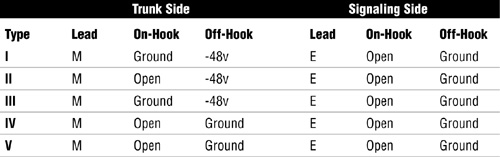
Type I is most common in the United States, while Type V is mostly used outside North America. Type IV is not supported on Cisco routers. Types II and V can be used to connect two signaling-unit side devices in a back-to-back configuration.
E&M circuits are most commonly used to connect to IP networks and tie lines. A tie line, which is a dedicated direct connect circuit, provides an analog interface between locations and typically terminates on an E&M interface in a Cisco router. For example, Communications Manager Express can use an E&M interface to provide a connection to an external Music on Hold (MoH) service.
For signaling in E&M circuits, you have three possible mechanisms for line seizure and passing address information, which is referred to as Start Dial Supervision, because they determine how dialing is accomplished in E&M circuits:
![]() Wink Start
Wink Start
![]() Delay Start
Delay Start
![]() Immediate Start
Immediate Start
Wink Start is the most common and reduces glare by providing Answer Supervision. When the call is being made, the originating side takes the M-lead off-hook (according to the type of E&M being used). The terminating end of the connection provides a “wink,” that is, an off-hook pulse, on the E-lead and goes back on-hook, indicating that it is ready to place a call. After 100ms, the originating switch begins the calling process. When the called party answers, the terminating end of the E&M connection indicates an off-hook to the originating end.
Delay Start waits for a configurable time before it begins the call. This solves a problem with some equipment that might start dialing too soon with Wink Start.
Immediate Start is the most basic type of Start Dial Supervision, but it does not include the supervision like Wink Start. The originating end goes off-hook and begins transmitting after 150ms.
|
1. |
B. The switch hook detects the off-hook and on-hook condition on the phone when the user lifts the handset. Answers A, C, and D are incorrect, because the ringer is only used to signal an incoming call, and the receiver and transmitter are used only after the call is connected. |
|
2. |
C. PRI is a digital signaling type used in T1 Common Channel Signaling (CCS) circuits. Answers A, B, and D are incorrect. FXO, E&M, and FXS are valid analog signaling types. |
|
3. |
A. Glare is the condition that occurs when both ends of the connection seize the line at the same time, due to the absence of Answer and Disconnect Supervision. Answers B, C, and D are incorrect. Trunk side signaling is used in E&M circuits. Answer Supervision provides remote signaling to eliminate glare. Wink Start is a signaling type used in E&M circuits. |
|
4. |
B. Loop start is most susceptible to glare, because there is no mechanism for Answer and Disconnect Supervision. Answers A, C, and D are incorrect. Ground start and E&M are less susceptible to glare. |
|
5. |
A and C. Ring and tip are leads used in loop start circuits. Answers B and D are incorrect. The E-lead and M-lead are used for signaling in E&M circuits. |
|
6. |
A and B. Answer Supervision and Disconnect Supervision allow remote signaling to the remote end to eliminate glare. Answers C and D are incorrect. Wink Start and Immediate Start are both E&M Start Dial Supervision types. |
|
7. |
B. Type VI does not exist. Answers A, C, and D are incorrect. Type I, Type IV, and Type II are all valid E&M signaling types. |
|
8. |
A. Type I is the most common E&M signaling type in the United States. Answers B, C, and D are incorrect. Type III, Type IV, and Type V are valid signaling types but not as common in the United States. Type V is common outside of North America. |
|
9. |
A. The E-lead is used by the trunk side for signaling. Answers B, C, and D are incorrect. The M-lead is used by the signaling-unit side. Ring and tip are used by loop start and ground start circuits. |
|
10. |
A, B, and D. Wink Start, Immediate Start, and Delay Dial are all valid Start Dial Supervision types. Answer C is incorrect. Loop start is a two-wire circuit type used in residential circuits. |