Terms you need to understand:
Techniques you need to master:
To make calls to destinations outside of a Cisco Unified Communications Manager Express (CME), you have to have some type of connectivity to outside networks. These foreign destinations can range from a coworker at another site to the pizza parlor down the street to someone on the other side of the world. For the most part, gateways are used to connect a Cisco Unified CME network to another network. This chapter explores the components and configuration of gateways.
The two key components covered in this chapter are call legs and dial peers. This chapter explores these components and describes how they are used within a gateway. Finally this chapter takes a brief look at how Cisco Unified CME can be connected to an Internet service provider (ISP).
The simplest definition of a gateway is a device that connects dissimilar systems. In the case of Cisco Unified CME, a gateway is used to connect to other phone networks. The most commonly connected system is the public switched telephone network (PSTN). The following sections explore the various types and functions of a gateway.
Exam Alert
Gateways are used to connect to traditional private branch exchanges (PBXs) as well as the PSTN.
Gateways are often classified by the type of circuit they are connected to. As explained in Chapter 2, “Introducing Analog Circuits,” and Chapter 3, “Introducing Digital Circuits,” there are two types of telephone circuits: analog and digital. The circuits are plugged into either analog or digital voice ports, depending on the type of circuit. The voice ports are part of the gateways. Gateways that have analog voice ports are referred to as analog gateways, and those that have digital voice ports are referred to as digital gateways.
Note
The hardware that functions as a gateway is most often a router. For that reason, the terms gateway and router are often used interchangeably. For this chapter, the term gateway is used, but on the test, the term router or gateway might be used.
There are three types of analog voice ports:
![]() Foreign Exchange Station (FXS): FXS ports connect to station equipment, and that station equipment could be an analog phone or fax machine.
Foreign Exchange Station (FXS): FXS ports connect to station equipment, and that station equipment could be an analog phone or fax machine.
![]() Foreign Exchange Office (FXO): FXO ports are ports that are circuits from the telephone central office (CO). You can also use this type of port to connect to a PBX.
Foreign Exchange Office (FXO): FXO ports are ports that are circuits from the telephone central office (CO). You can also use this type of port to connect to a PBX.
![]() recEive and transMit (E&M): E&M ports are typically used to terminate tie lines (a circuit between two sites).
recEive and transMit (E&M): E&M ports are typically used to terminate tie lines (a circuit between two sites).
Analog circuits are detailed in Chapter 2, so this section does not cover the details of analog circuits but rather focuses on the details of analog gateways. Analog gateways convert voice to Voice over IP (VoIP) packets for incoming calls and VoIP packets to voice for outbound calls.
Analog gateways are typically divided into two categories: analog station gateways and analog trunk gateways. Analog station gateways have FXS voice ports and are used to connect devices such as phones and fax machine to the VoIP network. An analog trunk gateway has FXO or E&M ports in them and is where circuits from the CO or a tie line are terminated.
Note
When connecting to the PSTN, the term POTS is sometimes used. POTS stands for plain old telephone system. It is exactly what it says: just the telephone system that we have known and loved for years.
There are a number of different types of digital circuits (described in detail in Chapter 3); therefore, there are a number of types of voice ports that can be used in a digital gateway. These various ports can be categorized into three types:
![]() Basic Rate Interface (BRI)
Basic Rate Interface (BRI)
![]() Primary Rate Interface (PRI)
Primary Rate Interface (PRI)
![]() Channel-associated signaling (CAS)
Channel-associated signaling (CAS)
A BRI circuit would terminate at the BRI port. You might recall from Chapter 3 that a BRI circuit has two 64Kbps channels that can be used for voice or data. These are referred to as B channels, and a separate 16Kbps channel, referred to as the D channel, is for signaling.
A PRI T1 or E1 terminates in a PRI port. PRI T1 circuits have 23 B channels and one D channel, while PRI E1 circuits have 30 B channels and one D channel. Both B and D channels are 64Kbps.
Just as with the PRI ports, a CAS T1 or E1 circuit terminates at a CAS port. The difference is that while the PRI circuits have a separate channel for signaling, the CAS port sends signaling using the same channel as the voice.
Note
A T1 port such as the VWIC2-1MFT-T1/E1 can support PRI or CAS. The configuration of the port is what determines whether it is PRI or CAS.
Gateways that contain digital ports are referred to as digital gateways. These types of circuits are most often used to connect an IP telephony network to the PSTN, but they can also be used to connect to traditional PBX and voicemail systems. The types of digital circuits that terminate in a digital gateway include BRI, PRI T1/E1, and CAS T1/ E1.
Digital gateways convert the incoming voice to VoIP packets and the outgoing VoIP packets to voice. Digital signal processors (DSPs) are used to accomplish this task.
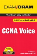
When a call is placed from point A to point B, there are a number of segments to the call. These segments are referred to as call legs. A call leg is a logical connection between two devices. Figure 6.1 shows that a call from a phone connected to an FXS port on a router to a phone connected to another FXS port on a different router has four call legs. At first, this seems odd because it shows two call legs between the two routers. It seems like there should be only one call leg because the call is going from Router A to Router B and there is no device between them. However, you have to look at it from the router’s perspective. Router A sees the call as having two call legs: one between itself and phone A (inbound) and one between itself and Router B (outbound). Router B sees the call as having two call legs: one between itself and phone B (outbound) and one between itself and Router A (inbound). Because each router has two call legs, the total number of call legs is four.
A good way to think of a call leg is that it is a logical connection between a gateway and any of the following:
![]() PBX
PBX
![]() IP trunk
IP trunk
![]() PSTN
PSTN
![]() Another gateway
Another gateway
![]() An analog device such as a phone
An analog device such as a phone
![]() Any Cisco call control product such as a Communications Manager
Any Cisco call control product such as a Communications Manager
When a call arrives at a gateway, the gateway must route the call to the correct destination. The destination is going to be either a voice port or an IP address. The mechanism used by the types of gateways that the test focuses on to route the call is called a dial peer. There are a number of types of dial peers. When the destination is a voice port, it is considered to be a POTS call. When the destination is an IP address, it is considered to be a VoIP call. There are primarily two types of dial peers: POTS dial peers and voice-network dial peers.
Dial peers are just a set of commands entered on the gateway. A single dial peer can be as simple as just a few lines or as many as eight. The number of commands that a dial peer requires is based on a number of factors. Let’s take a look at a simple dial peer.
Exam Alert
You should remember that both call legs and dial peers are thought of as logical connections.
To configure a dial peer, you need to be in the configure terminal prompt on the gateway. The prompt looks something like this:
GatewayName(config)#.
From this prompt, you issue the following commands, which create the dial peer:
CME(Config)# dial-peer voice 20 pots
CME(Config)# destination-pattern 2000
CME(Config)# port 0/0/1
The first time you enter the first command, the dial peer is created. If, in the future, you want to change the configuration of this dial peer, you would enter the same command. Let’s take a closer look at each piece of the first command. The following list defines each part of the dial-peer voice 20 pots command:
![]()
dial-peer: Instructs the gateway to create or enter for configuration purposes a dial peer.
![]()
voice: Instructs the gateway that this is going to be a voice dial peer as opposed to a data dial peer.
![]()
20: Denotes what is known as a tag number. The tag number can be anything you like, but each dial peer must have a unique tag number. The tag number is used when referencing this dial peer in other commands.
![]()
pots: Denotes that this dial peer is going to be a POTS dial peer. The valid parameters are pots, voip, vofr, and voatm. The next two sections go into more detail on POTS and VoIP dial peers.
The next command determines which numbers will match this dial peer. In this example, destination-pattern 2000 instructs the gateway that when it receives a call with the destination (dial number) of 2000, it should route it to the destination defined by this dial peer.
The last command determines where the call will be routed. In this example, port 0/0/1 instructs the gateway to send the call that matches this dial peer to port 0/0/1, which is a physical port on the gateway.
This is a fairly simple example, and we go into more detail on additional settings in the section “Dial Peer Commands,” later in this chapter. For now, just understand that dial peers determine how a call is routed and other properties of the call such as quality of service (QoS) markings fax rate, voice activity detection (VAD), and codec.
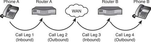
The example in the previous section shows how to configure a simple POTS dial peer. POTS dial peers are used when calls that match them are sent to a POTS voice port, such as an FXO or T1. Figure 6.2 shows an example of a configuration that would use a POTS dial peer.
In this figure, the phone is plugged into an FXS port on the gateway. Dial peer 20 will match if the router receives a call for the digits 2000. It then sends all matched calls to port 0/0/1, which has an analog phone plugged into it.
Note
A dial peer is often referred to by its tag number. For example, the dial peer example in Figure 6.2 would be referred to as “dial peer 20.”
VoIP dial peers are used to route a call to an IP device such as a Cisco Unified CME or another Cisco VoIP gateway. The configuration of a VoIP dial peer is similar to that for a POTS dial peer, but instead of defining a port as the destination of a call, you define an IP address as the destination.
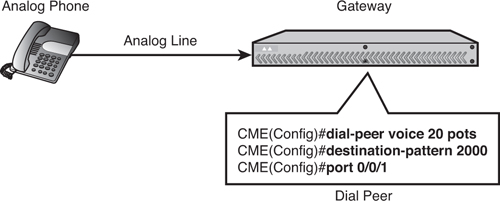
Figure 6.3 shows an example configuration that would use a VoIP dial peer.
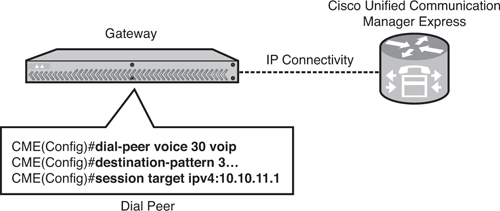
This first line in the dial peer found in Figure 6.3, dial-peer voice 30 voip, defines this dial peer as a VoIP dial peer with the tag of 30. The second line, destination-pattern 3..., instructs the gateway that any call where the dialed number is 3000–3999 matches this dial peer. The reason that 3... matches any number 3000–3999 is because the period (.) is a wildcard that matches any single digit 0–9. The last line, session target ipv4:10.10.11.1, instructs the gateway to route the call that matches this dial peer to the device with the IP address of 10.10.11.1, which in this case is the Cisco Unified CME.
Exam Alert
When a dial peer is set as VoIP, the gateway is instructed that it must route the call based on the settings in the dial peer. It must also convert the voice to IP packets for transmission across the network. The dial peer determines parameters such as the codec to use, whether VAD is enabled, packet priority, and whether Real-Time Transport Protocol header Compression (RTPc) is used.
Exam Alert
Be sure you know the following minimum steps required to configure a VoIP dial peer:
Now that we have discussed an overview of dial peers and the two types we are dealing with in this book, let’s dig deeper into the various commands that can make up a dial peer. The following sections show examples of a number of commands and provide explanations for each of them. The core commands of a dial peer appear in the preceding “Dial Peer Overview” section of this chapter, so let’s look at some of the other commands that can be part of a dial peer.
dial-peer voice 20 voip
For this example, we break down each portion of the command as follows:
![]()
dial-peer: Instructs the gateway to create or enter for configuration purposes a dial peer.
![]()
voice: Instructs the gateway that this is going to be a voice dial peer as opposed to a data dial peer. Valid parameters are voice and data.
![]()
20: Denotes what is known as a tag number. The tag number can be anything you like, but each dial peer must have a unique tag number.
Note
VOFR stands for Voice over Frame Relay, and VoATM stands for Voice over ATM. Neither of these types of dial peers is covered in this book because they are outside the scope of the exam.
The destination-pattern command determines which dialed digits match this dial peer. For example, in the destination-pattern 2000 command, the number 2000 means that when the router receives a call for a destination with the dial digits of 2000, the dial peer is a match. The valid parameters that can follow the destination-pattern command are a string of numbers and wildcards. A list of valid wildcards follows:
![]() Period (
Period (.): Matches a single digit 0 through 9. For example, 500. matches 5000, 5001, 5002, 5003, 5004, 5005, 5006, 5007, 5008, and 5009.
![]() Comma (
Comma (,): Inserts a pause. This is useful when a 9 is dialed to signal to the PBX to seize a PSTN trunk. The comma in the string gives the PBX a moment to seize the trunk before the rest of the digits are sent.
![]() Plus sign (
Plus sign (+): Indicates that the preceding number occurs one or more times. For example, the pattern 517565.+ matches any number that begins with 517565 and is followed by one or more digits.
![]() Percent sign (
Percent sign (%): Indicates that the preceding number occurs zero or more times.
![]() Brackets
Brackets [ ]: Indicate a range. A range is a sequence of characters enclosed in the brackets. The range can only contain single digits, such as [0-9]. For example, 240[2-7] would match 2402, 2403, 2404, 2405, 2406, and 2047.
![]()
T: In short, the T matches any digits and any number of digits. This is useful when a variable-length daily plan is needed, for example, to allow callers to dial local, long-distance, and international calls. Because the T can match a large number of digits (no more than 32), the interdigit timeout value is used to decide when the gateway stops collecting digits and attempts to find a matching dial peer. On certain types of trunks, there can be a pause at the end of dialing equal to the interdigit timeout value, which is normally 10 seconds. The caller can expedite this process by pressing the # button on the phone, which terminates interdigit timeout.
The session target command is used in VoIP dial peers and determines what IP address the call is routed to. For example, in the session target ipv4:10.10.11.1 command, the call will be routed to the device with the IP address of 10.10.11.1.
The port command is used in POTS dial peers and determines which physical port on the gateway the call will be sent out. For example:
port 0/0/1
The codec command determines which codec will be used for this dial peer. The valid codecs that can be selected vary based on the gateway. Typically you can select from the following: g711alaw, g711ulaw, g722-64, g723ar53, g723ar63, g723r53, g723r63, g726r16, g726r24, g726r32, g728, g729r8, and g729br8. The default codec for a VoIP dial peer is g729r8. For example:
codec g711ulaw
The preference command is used to determine which dial peer a call should be routed to first when all the dial peer matches are the same, for example, when all matched dial peers have the same destination pattern. This is useful when configuring hunting. Listing 6.1 shows how this might be used.
In Listing 6.1, when a call in which the dialed digits are 5551000 reaches the gateway, three matches are found. Because the preference determines which dial peer should handle the call and the lowest preference is tried first, the call would be routed to port 0/0/0. If the device on port 0/0/0 were busy or unavailable, the call would be sent to port 0/0/1 because the dial peer that points to that port has a preference of 2. Finally, if port 0/0/1 were busy or unavailable, the call would be routed to port 0/1/0 because the dial peer that points to that port has a preference of 3.
Note
In Listing 6.1, the dial peer tag numbers have no effect on which dial peer is used. Only the preference number determines the hunting algorithm when there are multiple exact matches.
Often the preference command is not seen when you look at a dial peer configuration. That is because the default preference is 0, and most defaults do not show up in a running config.
Caution
You should understand that if there are two or more dial peers that a call matches equally—for example, the destination-pattern is the same for all matched dial peers and preference is not assigned—all the dial peers will have a preference of 0 and the gateway will randomly select one of the dial peers. This can result in unexpected call routing.
The vad command determines whether the gateway will use voice activity detection (VAD). The VAD feature allows the gateway to reduce the amount of bandwidth required for a call by only sending data when there is voice. That is to say that when one party is not talking, nothing is sent from that side. Because a conversation can be as much as 60 percent silence, this feature can save a significant amount of bandwidth.
The problem with VAD is that due to the mechanics of how it works, there can often be voice cutoff at the beginning of statements. For that reason, many people issue the no vad command to turn off this feature. While it adds to the required bandwidth, it improves the caller’s experience. VAD is enabled by default.
The ip precedence command is used to assign a high priority to the packets coming from the dial peer. The default is 0. The valid options are 0–7, with the higher number having the higher precedence. For example:
ip precedence 1
So far, we have looked at one way that a call matches a dial peer, that is, by matching the dial digits to the destination pattern of a dial peer. While this is a common method, it is only one of several. The gateway processes two types of calls: inbound and outbound. The way it matches a dial peer is different for these two types of calls. Based on the type of call that is being routed, a dial peer is referred to as an inbound dial peer or an outbound dial peer.
For inbound dial peers, the gateway tries to match on four parameters. This is a sequential process. In other words, it tests each of the following in the following order. When it finds a match, it routes the call:
1. The incoming called number command is used to define the Dialed Number Identification Service (DNIS) that an inbound call has to match in order to match the dial peer. For example, incoming called number 8105551... would match an incoming call from the DNIS 8105551000–8105551999. This command can be used for both POTS and VoIP dial peers.
2. The answer address command is used to match an incoming dial peer based on the E.164 telephone number of an incoming call. This command is only used for VoIP dial peers.
3. The destination-pattern command is discussed in the “Dial Peer Commands” section, earlier in this chapter.
4. The port command is discussed in the “Dial Peer Commands” section of this chapter. When this command is used, it matches the dial peer based on the port that the call came in on.
5. The default dial peer 0 is a dial peer that you do not have to create and you cannot modify. It is in the system by default and you never see it. It is used to handle calls that do not match any other dial peer.
Tip
You can create what some refer to as a “catch-all” dial peer. This allows you to determine where all calls that do not match any other dial peer are routed to.
The default dial peer configuration for inbound VoIP calls are any codec, VAD enabled, IP precedence 0, fax-rate voice, and no rsvp support. The default dial peer configuration for inbound POTS calls contains the no ivr application command.
Determining the outbound dial peer is much easier than determining the inbound dial peer. The gateway does a digit-by-digit match on the dial number against the destination pattern and selects the first/best match. The best way to explain this is to look at a couple of examples. Listing 6.2 shows what happens when multiple dial peers with the same-length destination pattern match. The dial peers are configured in a gateway.
Listing 6.2 Dial Peer Matching
dial-peer voice 50 VOIP
 destination-pattern 555....
 session target ipv4:10.10.11.1

dial-peer voice 60 VOIP
 destination-pattern 5551...
 session target ipv4:10.10.11.1

dial-peer voice 70 VOIP
 destination-pattern 55512..
 session target ipv4:10.10.11.1

dial-peer voice 80 VOIP
 destination-pattern 5551230
 session target ipv4:10.10.11.1
When an outgoing number is 5551230, dial peer 80 is used because even though all the dial peers match, dial peer 80 is the closest. The closet match is determined by how many “matches” each dial peer has, that is, how many different numbers match the destination pattern. Dial peer 50 would match 10,000 numbers (5550000–5559999). Dial peer 60 matches 1,000 numbers (5551000–5551999). Dial peer 70 matches 100 numbers (5551200–5551299). Dial peer 80 only matches one number (5551230).
When an outgoing number is 5552000, dial peer 50 is used because none of the other dial peers match.
Listing 6.3 shows how the first match is chosen when dial peers have different length destination patterns. The dial peers in the gateway are shown.
When an outgoing number is 5551230, you would expect dial peer 70 to be used. However, because the matching is done on a digit-by-digit basis, the gateway routes a call as soon as it finds a match. In this case, the first digit the gateway receives is a 5 and is a possible match for all three dial peers, so the gateway waits for another digit. The second digit the gateway receives is a 5. The gateway now has 55, and because that is a possible match for all dial peers, the gateway waits for another digit. The third digit the gateway receives is a 5. Now the gateway has 555, and it is an exact match for dial peer 50, so it routes the call even though there are other digits yet to be sent. In this example, dial peers 60 and 70 would never be used.
This section is a brief overview of how to connect to an Internet telephony service provider (ITSP). ITSPs are relatively new. They basically provide a customer with an IP trunk that the customer uses to route PSTN-bound calls. The ITSP trunks are typically SIP based but can also be H.323. The call is sent to the ITSP through an IP connection, and the ITSP routes the call to the PSTN.
There are many benefits to ITSP trunks. The first and most attractive is the reduced cost.
Exam Alert
These trunks are typically less expensive for both the circuit and the long-distance fees. Another benefit is that when the bandwidth is not being used for voice, it can be used to transport data. The number of lines can be incremented one at a time, which is another benefit over a circuit like a T1, which contains 24 channels.
To connect to an ITSP, create a VoIP dial peer using the parameters provided by the ITSP.
|
1. |
E. Answers A, B, C, and D are all correct statements about an analog voice port. |
|
2. |
D. E&M is an analog port. Answers A, B, and C are incorrect because PRI T1, CAS E1, and BRI are all digital voice ports. |
|
3. |
A. A call leg is a logical connection between two devices. Answer B is incorrect because |
|
D. An outbound dial peer matches on the first match, even if it is not the most exact match. Answers A, B, and C are true statements. |
|
|
5. |
C. While it looks okay, the |
|
6. |
D. Remember that the default preference is 0. Also remember that many defaults do not show up in a running config. Because no preference was listed in this dial peer, the preference was 0, and the dial peer with the lowest preference is the one that is selected. Answers A, B, and C are incorrect because each of them has a preference higher than 0. |
|
7. |
A. After searching for an inbound dial peer match based on the |
|
8. |
A, B, C, and D. An inbound dial peer matches based on the |
|
9. |
D. The destination pattern is only five digits long, and the gateway routes based on the fastest match. Because answers A, B, and C all have 7-digit destination patterns, they will never match because the call will have been routed before the gateway receives the seventh digit. |
|
10. |
B. A VoIP dial must be created when connecting to an ITSP. Answers A, C, and D are not valid dial peer types. |
1. Cisco. “Understanding Dial Peers and Call Legs on Cisco IOS Platforms.” http://tinyurl.com/47g39u.