
Terms you need to understand:
Techniques you need to master:
|
|
|
|
|
|
|
|
Configure auto registration |
|
|
Verify phone configuration and registration |
In this chapter, you learn about the configuration needed to allow phones to register to a Cisco Unified CME. For each physical phone that can register to a Cisco Unified CME, you must configure an ephone in the Cisco Unified CME. In addition, for each phone number assigned to a phone, you must configure an ephone-dn. So, before we look at global telephony configurations, let’s take a look at these two concepts.
An ephone is just a set of Cisco Unified CME entries that define how a phone will be configured. The ephone configuration defines the number of directory numbers (DNs), speed dials, and MAC address. While the ephone configuration defines which DNs are assigned to the phone, the DNs themselves must be configured separately. This is done by creating ephone-dns. A good way to think of this is that an ephone is the software configuration of the hardware device.
Before you can create ephones, you need to define how many ephones will be allowed to register to the Cisco Unified CME. While the hardware platform determines the maximum number of phones that the hardware can support, you might not want that many phones to register to the Cisco Unified CME. The router reserves memory based on the number of phones it is configured to support. By default, the maximum is set to 0. The command used to set the maximum number of ephones is
max-ephones number
For example, if you want to configure the Cisco Unified CME to allow 15 phones to register, you would enter max-ephones 15. This command must be issued from telephony-service configuration. You can enter telephony-service configuration by entering telephony-service from the global configuration prompt.
Note
The number you set for max-ephones must be within the limitation of the router and the license.
After you define the maximum number of ephones, you can create ephones. Creation of an ephone is done from the global configuration mode on the Cisco Unified CME router. The command to create an ephone is as follows:
ephone phone-tag
The phone-tag parameter is a number that is used to identify this ephone. A phone-tag can be any number you choose, but each ephone must have a unique phone-tag. To create an ephone using 10 as the phone tag, you would enter ephone 10.
Using the ephone phone-tag command creates an ephone. However, that alone does not allow a phone to register. After you create the ephone, you must configure it. After an ephone is created, the prompt changes to show that you are in ephone configuration. The prompt looks something like the following:
router (config-ephone)#
From this prompt, you can define various parameters of the ephone. You first must define the MAC address of the phone and the DN(s) that will be assigned to the phone. To define the MAC address, enter the mac-address command followed by the MAC address. The MAC address must be in the proper format. As you know, a MAC address is 12 hexadecimal characters long. The format used to assign one to an ephone is four sets of four hexadecimal characters. The following is an example for defining the MAC address of 00CC0001A1231ABF to ephone:
mac-address 00CC.0001.A123.1ABF
To assign a DN to the phone, you must first create an ephone-dn. The next section covers how to create and assign ephone-dns.
An ephone-dn represents a line that can be assigned to an ephone to allow a voice channel. An ephone-dn can have one or more numbers assigned to it. Just think of an ephone-dn as being equal to a line on a phone.
The configuration of an ephone-dn is fairly simple, but before you create one, you should define the maximum number of DNs that you want the Cisco Unified CME to allow to register. By default, this is set to 0. This is similar to how you had to define the maximum number of ephones that could register. The command is max-dn number, where number is the number of DNs the router is to support. To configure the router to support 24 DNs, you would issue the following command at telephony-service configuration:
max-dn 24
To create an ephone-dn, two commands must be entered. First, use the following command to create the ephone-dn:
ephone-dn dn-tag
The dn-tag parameter is a number that is used to identify this ephone-dn. It is not a directory number. It is only used to identify the ephone-dn. A dn-tag can be any number you choose, but each ephone-dn must have a unique dn-tag. To create an ephone-dn using 101 as the dn-tag, you would enter ephone-dn 101.
Next you need to define the directory number that will be associated with this ephone-dn. This is done using the number command. After you create an ephone-dn, you will be in ephone-dn configuration mode.
The following commands show how to create an ephone-dn with a dn-tag of 101 and a directory number of 2001:
ephone-dn 101number 2001
Now that you know how to create a basic ephone-dn, let’s take a look at how it is assigned to an ephone. To enter the configuration mode for an ephone, you issue the same command you did when you first created the ephone, which is ephone phone-tag. If the ephone exists, you will enter the configuration mode for it; if it doesn’t, the ephone will be created and you will enter the configuration mode for it. After you are in ephone configuration mode, you assign an ephone-dn to a button on the phone by using the button command. The syntax for the button command is button button-number{separator}dn-tag. For example, to assign the ephone-dn 101 to the second button on the phone, you would enter button 2:101. This command does not assign the extension number 101 to the second button. It assigns the extension number that is associated with ephone-dn 101. Let’s take a look at a complete example of creating a phone with the following characteristics:
![]() Ephone tag of 10
Ephone tag of 10
![]() MAC address of 00CC0001A1231ABF
MAC address of 00CC0001A1231ABF
![]() Two extension numbers, 2000 and 2001
Two extension numbers, 2000 and 2001
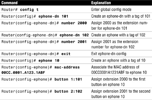
Listing 10.1 includes the router prompts so that you can see what config mode the commands are entered in.
Listing 10.1 Ephone and Ephone-dn Configuration
Router# config t
Router(config)# ephone-dn 101
Router(config-ephone-dn)# number 2000

Router(config-ephone-dn)# ephone-dn 102
Router(config-ephone-dn)# number 2001
Router(config-ephone-dn)# exit
Router(config)# ephone 10
Router(config-ephone)# mac-address 00CC.0001.A123.1ABF
Router(config-ephone)# button 1:101
Router(config-ephone)# button 2:102
To better understand each of these commands, take a look at Table 10.1, which lists each command and offers a brief explanation.
As you know, the button command defines what ephone-dn is assigned to a button on the phone. But it does more than that: It also defines how the ephone-dn is assigned. How an ephone is assigned to a button impacts how it will function. In the command button 1:101 the colon (:) is referred to as a separator. The separator is used to define how the button will function. There are nine different separators. So far, we have only looked at the colon, which configures the line to act normally, that is, to ring normally and function in much the way you would expect a phone line to function. The following is a list of the other operators that can be used and a brief explanation for each one:
![]()
b (Beep): Does not ring incoming calls, but beeps are heard when you are on the phone and another call is coming in. The lights and other visible indicators function normally.
![]()
o (Overlay): Assigns multiple ephone-dns to a single button, a maximum of 25 on a button.
![]()
c (Call waiting): Allows call waiting for an overlaid ephone-dn.
![]()
x (Overlay rollover): Allows a call to an occupied overlay button to ring on this button.
![]()
f (Feature ring): Causes the phone to play a ringer three times quickly to differentiate calls coming in on this line.
![]()
m (Monitor): Allows you to monitor the status of the DN. Cannot be used to place or receive calls.
![]()
s (Silent): Does not play ringing and call waiting beep for incoming calls. The flashing icon is the only indication that a call is coming in on the line.
![]()
w (Watch): Shows the status of all lines on a phone that have the primary number assigned in this command.
Let’s take a look at a couple of examples. If you were to configure a button as follows, the ephone-dn 101 would be assigned to the first button on the phone, and when a call came in on that line, it would not ring. But, if a person were already on a call when a new call arrived, the person would hear the call waiting beep:
button 1b101
If a button were configured as follows, ephone-dn 101 would be assigned to the fourth button and would be used to monitor the status on the extension assigned to ephone-dn 101. This line could not be used to place or receive calls:
button 4m101
You should now understand how to create basic ephones and ephone-dns and associate ephone-dns to buttons. Up to now, we have been discussing basic single-line ephone-dns. Ephone-dns can be configured to function in a number of different manners. The following sections explore six types of ephone-dns:
![]() Single-line
Single-line
![]() Dual-line
Dual-line
![]() Dual-number
Dual-number
![]() Shared
Shared
![]() Multiple ephone-dns
Multiple ephone-dns
![]() Overlay
Overlay
This section describes the single-line ephone-dn. A single virtual voice port is created when a single-line ephone-dn is configured. A virtual voice port allows a single call. If you need a line that can support more than a single call, a single-line ephone-dn will not work. Features such as call waiting, call transfer, and conferencing do not work on single-line phones. If you want these features with single-line ephone-dns, you must configure more than one single-line ephone-dn on the phone.
Single-line ephone-dns have a single number assigned to them, but a secondary number might also be assigned. Typical uses for single-line ephone-dns are intercoms, paging, Music on Hold (MoH) sources, loopbacks, and Message Waiting Indicators (MWIs). They are also useful when phones are configured to have a one-to-one relationship to public switched telephone network (PSTN) lines.
Exam Alert
Typical uses for single-line ephone-dns are intercoms, paging, MoH sources, loopbacks, and MWIs.
The following commands are required to create a single-line ephone-dn and assign 2001 as its extension number:
ephone-dn 101number 2000
A dual-line ephone-dn allows two active calls on a single line (single button). There is still a single virtual voice port, but the voice port has two channels, thereby allowing two calls. It can have a primary and secondary number associated with it and supports features such as call waiting, call transfer, and conferencing.
Exam Alert
Dual-line ephone-dns should not be used for intercoms, paging, MoH sources, loopbacks, MWIs, or call park slots.
The following commands are required to create a dual-line ephone-dn and assign 2001 as its extension number:
ephone-dn 101 dual-linenumber 2000
A dual-number ephone-dn is just an ephone-dn with two numbers, a primary and secondary, assigned to it. You can configure single-line ephone-dns and dual-line ephone-dns as dual-number ephone-dns. The type of ephone-dn allows you to assign two numbers to a single button. This is often used to assign the internal and fully qualified number to an ephone-dn.
The following commands are required to create a dual-number ephone-dn and assign both 2001 and 5155552001 as extension numbers:
ephone-dn 101 dual-linenumber 2000 secondary 5155552001
These commands create the ephone-dn as a dual-line, but it could also have been a single-line ephone-dn.
A shared ephone-dn is an ephone-dn that is assigned to multiple phones. This allows a call coming to that DN to be answered from any phone that has the ephone-dn assigned to it. After the call is answered, the shared-line appearance on the other phones is not available for use. If the call is placed on hold, it can be picked up from any phone that has that an ephone-dn assigned to it. Listing 10.2 shows how a shared ephone-dn is configured.
Listing 10.2 Configuring a Shared Ephone-dn
Router(config)# ephone-dn 101 dual-line
Router(config-ephone-dn)# number 2000
Router(config)# ephone 10
Router(config-ephone)# mac-address 00CC.0001.A123.1ABF
Router(config-ephone)# button 1:101
Router(config)# ephone 12
Router(config-ephone)# mac-address 00C0.0011.A145.1DDA
Router(config-ephone)# button 1:101
Listing 10.2 shows how extension number 2000 is assigned to the first button of ephone 10 and ephone 12.
You can create multiple ephone-dns that have the same extension number. You might want to do so for a number of reasons. For example, it is common in some older systems to have multiple line appearances with the same number, or you might want a phone to be able to accept more than two calls on the same extension number.
Exam Alert
You must understand that creating more than one ephone-dn with the same extension number and placing each of them on different phones is not the same as having a shared line. Each ephone-dn is a separate extension, even if the same number is assigned.
The concept of multiple ephone-dns can sound confusing, but it is no different than two people that have the same name. Even though both of them can have the name Toby, they are not the same person. So the question is, when a call comes in to 1001 and there are two ephone-dns that have 1001 assigned, how does Cisco Unified CME know which ephone-dn to send the call to? The decision is made based on the preference that is assigned to the ephone-dn. Chapter 6, “Connecting Your VoIP System to the Rest of the World,” covers preference in the dial-peers discussion. Preference works the same way with ephone-dns as it does with dial-peers. The ephone-dn with the lower preference is selected if available.
Let’s look at the configuration. We look at scenarios for two common uses of multiple ephone-dns. In the first scenario, you need to have two phones with the same extension, but you do not want a shared line. For example, you might have a main receptionist that answers incoming calls, but if the receptionist is unable to take the call, it can be routed to another phone. Listing 10.3 shows the configuration for two phones to accomplish this. The commands that are grayed are associated with the phone that has the MAC address of 0C00011A1451DDA. The other commands are associated to the other phone.
Listing 10.3 Multiple Ephone-dns with the Same Number on Separate Phones
Router(config)# ephone-dn 101 dual-line
Router(config-ephone-dn)# number 2000
Router(config-ephone-dn)# Preference 1
Router(config)# ephone-dn 201 dual-line
Router(config-ephone-dn)# number 2000
Router(config)# ephone 10
Router(config-ephone)# mac-address 0CC.0001.A123.1ABF
Router(config-ephone)# button 1:101
Router(config)# ephone 12
Router(config-ephone)# mac-address 0C0.0011.A145.1DDA
Router(config-ephone)# button 1:201
The commands that are associated for each phone are highlighted. You see that phone A has been defined as ephone 10. Ephone 10 has ephone-dn 101 assigned to it, and the extension 2000 is associated with ephone-dn 101. Phone B has been defined as ephone 12. Ephone 12 has ephone-dn 201 assigned to it, and the extension 2000 is associated with ephone-dn 201. The result is that both phones have the extension 2000 assigned to their first button, but because different ephone-dns were used, this is not considered a shared line. Therefore, when a call arrives for extension 2000, Cisco Unified CME needs to decide which of these two devices the call will be sent to. Looking at Listing 10.3 again, you see that ephone-dn 101 has a preference of 1. Ephone-dn 201 has no preference assigned. Remember, if no preference is assigned, the default preference used is 0. Because ephone-dn 201 has a lower preference, the call will be routed to phone B. If phone B is busy, the call can be routed to phone A, if so configured.
The huntstop command is used to determine whether a call will be routed to phone A when phone B is busy. Huntstop determines whether hunting will occur. Hunting is when a call goes from one ephone-dn to another until it finds an available voice channel. In other words, a call will “hunt” for an available line. A dual-line ephone-dn has two virtual voice channels; therefore, if the ephone-dn is a dual-line, huntstop for the channel is also configured. The huntstop command with no keywords configures huntstop for the ephone-dn. The huntstop command with the channel keyword configures hunting for the channels; that is, the huntstop channel configuration determines whether the call will hunt to the second channel of a dual-line ephone-dn. Huntstop is enabled on an ephone-dn by default. This means that, by default, a call will not hunt to another ephone-dn if the ephone-dn with the lowest preference is busy or not answered. However, no huntstop channel is the default for channel huntstop. This means that if the first channel of an ephone-dn is busy, the call will hunt to the second channel.
Let’s expand on the previous listing. Listing 10.4 shows the same example that was seen in Listing 10.3 with the addition of huntstop commands.
Listing 10.4 Multiple Ephone-dns with the Same Number on Separate Phones and Huntstop Configured
Router(config)# ephone-dn 101 dual-line
Router(config-ephone-dn)# number 2000
Router(config-ephone-dn)# huntstop channel
Router(config-ephone-dn)# Preference 1
Router(config)# ephone-dn 201 dual-line
Router(config-ephone-dn)# number 2000
Router(config-ephone-dn)# huntstop channel
Router(config-ephone-dn)# no huntstop
Router(config)# ephone 10
Router(config-ephone)# mac-address 00CC.0001.A123.1ABF
Router(config-ephone)# button 1:101
Router(config)# ephone 12
Router(config-ephone)# mac-address 00C0.0011.A145.1DDA
Router(config-ephone)# button 1:201
You see that ephone-dn 201 has no huntstop configured. This means that if ephone-dn 201 is busy or unanswered, the call will continue to hunt, but because huntstop channel is also configured, it will not hunt to the second channel of the ephone-dn. Instead, it will hunt to an other ephone-dn that has 2000 as its extension; therefore, it will hunt to ephone-dn 101. Ephone-dn 101 has huntstop channel configured but no other huntstop command, which means the default will be used. The default for huntstop is enabled; therefore, the hunting will stop if the first channel of ephone-dn 101 is busy or unanswered.
Now that you understand how to configure multiple ephone-dns with the same number of separate phones, let’s look at how you configure multiple ephone-dns on a single phone. By doing this, you can allow a phone to accept more than two calls placed to the same extension. The best way to understand this is by looking at an example. Listing 10.5 shows the configuration of a phone that has two ephone-dns with the same number assigned to it. The dark gray commands define the ephone. The light gray commands define an extension of 2000 that is assigned to the second button. The other commands define an extension of 2000 that is assigned to the first button.
Listing 10.5 Multiple Ephone-dns with the Same Number on a Single Phone with Huntstop Configured
Router(config)# ephone-dn 101 dual-line
Router(config-ephone-dn)# number 2000
Router(config-ephone-dn)# no huntstop
Router(config)# ephone-dn 201 dual-line
Router(config-ephone-dn)# number 2000
Router(config-ephone-dn)# Preference 1
Router(config)# ephone 10
Router(config-ephone)# mac-address 00CC.0001.A123.1ABF
Router(config-ephone)# button 1:101
Router(config-ephone)# button 2:201
In Listing 10.5, ephone-dns 101 and 201 have the same extension. Ephone-dn 101 is assigned to the first button on the phone, and 201 is assigned to the second button. This results in two lines with the same extension. When the Cisco Unified CME receives a call for 2000, it uses the preference command to determine which line to send the call to. Because ephone-dn 101 has no preference set, it uses the default of 0. Because ephone-dn 201 has a higher preference (1), the call is routed to ephone-dn 101. If the first voice channel on ephone-dn 101 is busy, the call will roll over to the second channel on 101. This happens because the huntstop channel is set by default. If both channels on ephone-dn 101 are busy, the call will hunt to ephone-dn 201. This happens because ephone-dn 101 has no huntstop configured. If the first channel of ephone-dn 201 is busy, the call will roll over to the second channel and, if that channel is busy, hunting will stop because huntstop is the default of an ephone-dn.
The last type of ephone-dn that is discussed is the overlay. An overlay ephone-dn allows you to assign as many as 25 numbers to a single button. So an overlay ephone-dn is really a set or group of ordinary ephone-dns. All the ephone-dns that are part of an overlay group must all be either single- or dual-line ephone-dns. That is, you cannot mix single- and dual-line ephone-dns in the same overlay group. The number assigned to the ephone-dns can have unique numbers or the same numbers as other ephone-dns within the overlay group. The same overlay group can be assigned to multiple phones.
An overlay ephone-dn is created when you assign an ephone-dn to a button. You already know that you assign an ephone-dn to a phone using the button command. You might also remember that when you use the letter o as a separator instead of the colon (:), it defines the button as an overlay. Listing 10.6 shows the commands required to configure a button on a phone as an overlay.
Listing 10.6 Configuring an Overlay
Router(config)# ephone-dn 101 dual-line
Router(config-ephone-dn)# number 1000
Router(config)# ephone-dn 201 dual-line
Router(config-ephone-dn)# number 2000
Router(config)# ephone-dn 301 dual-line
Router(config-ephone-dn)# number 3000
Router(config)# ephone 12
Router(config-ephone)# mac-address 00C0.0011.A145.1DDA
Router(config-ephone)# button 1o101,201,301
This listing would assign the extensions 1000, 2000, and 3000 to the first button of ephone 12. The first ephone-dn assigned appears on the display, which in this case is 1000. Cisco Unified CME will route calls placed to extensions 1000, 2000, or 3000 on this line. An overlay ephone-dn can be assigned as a shared line on multiple phones. As you recall, normally when a shared line is in use, the other phones that share that line cannot use it. This is not the case when an overlay is assigned as a shared line. Listing 10.7 expands the previous example by assigning the overlay to three phones.
Listing 10.7 Assigning Overlay to Three Phones
Router(config)# ephone-dn 101 dual-line
Router(config-ephone-dn)# number 1000
Router(config)# ephone-dn 201 dual-line
Router(config-ephone-dn)# number 2000
Router(config)# ephone-dn 301 dual-line
Router(config-ephone-dn)# number 3000
Router(config)# ephone 12
Router(config-ephone)# mac-address 00C0.0011.A145.1DDA
Router(config-ephone)# button 1o101,201,301
Router(config)# ephone 14
Router(config-ephone)# mac-address 00C0.0011.A145.B0BC
Router(config-ephone)# button 1o101,201,301
Router(config)# ephone 16
Router(config-ephone)# mac-address 00C0.0011.A145.65EF
Router(config-ephone)# button 1o101,201,301
In Listing 10.7, ephones 12, 14, and 16 are assigned extensions 1000, 2000, and 3000. If ephone 12 takes a call placed to extension 1000, ephones 14 and 16 can still use line 1 to place outbound calls because extensions 2000 and 3000 are available. Also, if a call comes in on extension 2000 or 3000 while ephone 12 is on a call using extension 1000, ephones 14 and 16 will ring.
In the previous sections, you learned about two commands that you can enter to configure telephony services. The max-ephones and max-dns commands are used to determine how many phones and directory numbers can register to the Cisco Unified CME. You still need to configure telephony service parameters before the phones can register to Cisco Unified CME and make phone calls.
The following sections describe the commands to configure telephony service parameters.
The Cisco Unified CME communicates with endpoints through a number of protocols; one of the most commonly used protocols is Skinny Client Control Protocol (SCCP). You must configure Cisco Unified CME so that it knows which interface and TCP port to use when communicating with SCCP endpoints. The default TCP port is 2000 and is typically not changed. The command used to configure this is ip source-address followed by the IP address of the interface on the Cisco Unified CME that will service SCCP requests. To configure the interface with the IP address of 10.1.1.10 to receive and respond to the SCCP requested, use the following command:
ip source-address 10.1.1.10
To include a port number other than 2000, add the keyword port and then the port number. For example, to issue the same command but change the TCP port to 2020, use the following command:
ip source-address 10.1.1.10 port 2020
Another setting that you configure in telephony-service configuration mode is keepalives. This command determines how often keepalive packets are sent between the Cisco Unified CME and Cisco IP phones. The default is 30. To change this value, use the keepalive command followed by the number of seconds you want to set it to. The range is 10–65535 seconds. For example, to change the keepalive value to 45 seconds, issue the following command:
keepalive 45
Extensions for ephone-dns are often the last four or five digits of the E.164 number that is to be associated with the phone. When placing an outbound call, you typically want the full E.164 number to be sent out. The dialplan-pattern command is used to accomplish this.
You also can use the dialplan-pattern command to transform full E.164 incoming numbers to their extension numbers. This is useful in an environment in which there are multiple Cisco Unified CMEs. When a call leaves one Cisco Unified CME, it matches the dialplan-pattern and is expanded into the full E.164. When the call reaches the other Cisco Unified CME, it again matches the dialplan-pattern and is reduced to its extension number so that the called party sees the calling party’s extension number instead of the full E.164. This also causes the incoming call to have a ring that is different than a normal external call, hence alerting the called party that it is an internal call.
Exam Allert
The dialplan-pattern command is also used when the lines need to register to a gatekeeper. By default, numbers that match the dialplan-pattern register to a gatekeeper if one is available. Use the no-reg keyword at the end of the dialplan-pattern command to prevent this.
The following is an example of a dialplan-pattern command:
dialplan-pattern 1 2485479... extension-length 4 extension-pattern 90..
Let’s take a closer look at each section of this command:
![]()
dialplan-pattern 1 defines that a dialplan-pattern is being configured. The 1 in the command is simply a tag. The tag defines this dialplan-pattern as dialplan-pattern number 1.
![]()
2485479... determines what numbers will match this dialplan-pattern and what outbound numbers it will be expanded to.
![]()
extension-length 4 determines how many digits inbound numbers that match this pattern will be stripped to. For example, if the dial number was 4085551001 and the extension length was set to 4, the number would be stripped to 1001.
![]()
extension-pattern 90.. determines how the number will further be transformed before appearing as internal caller ID.
So, with the preceding example, an outbound caller ID would be changed for the 4-digit extension of, say, 9091 to 2485479091. The caller ID of an inbound call for 2485479023 would match this dialplan-pattern and be transformed to 9023.
You also need to configure the date and time format. Two commands are used to do this. The first is the date-format command. The syntax for this command is date-format followed by one of the four following format options: mm-dd-yy, dd-mm-yy, yy-dd-mm, or yy-mm-dd. The other command is the time format, and it determines whether a 12- or 24-hour clock is used. The command is time-format followed by either 12 or 24.
The last configuration commands are those used to configure locale information. There are two locale commands. One determines the language that is displayed on the phone and the other determines the progress tones. Use the user-locale command followed by the two-letter language code for the language you desire. The valid language codes are
![]()
DK: Danish
![]()
ES: Spanish
![]()
FR: French
![]()
IT: Italian
![]()
JP: Japanese
![]()
NL: Dutch
![]()
NO: Norwegian
![]()
PT: Portuguese
![]()
RU: Russian
![]()
SE: Swedish
![]()
US: United States
You use the network-locale command to set the progress tones. Just as with the user-locale command, the network-locale command is followed by the language code for the desired progress tones. The valid language codes for progress tones are
![]()
AT: Austria
![]()
CA: Canada
![]()
CH: Switzerland
![]()
DE: Germany
![]()
DK: Denmark
![]()
ES: Spain
![]()
FR: France
![]()
GB: United Kingdom
![]()
IT: Italy
![]()
JP: Japan
![]()
NL: Netherlands
![]()
NO: Norway
![]()
PT: Portugal
![]()
RU: Russian Federation
![]()
SE: Sweden
![]()
US: United States (default)
Phones require the correct firmware to register to and work with Cisco Unified CME. There are specific firmware files for each model of Cisco IP phone. The phone retrieves these files through TFTP. TFTP must be configured on the Cisco Unified CME to allow the serving of the required firmware files. The tftp-server command is done in global config mode. The tftp-server command is used to determine which files are going to be available. The command syntax follows:
tftp-server flash:filename
The flash keyword specifies that the file is in flash. The filename parameter is the name of the file that needs to be served. Because some Cisco IP phone models need multiple files, the tftp-server command needs to be issued a number of times.
Consider the Cisco Unified IP Phone 7961G running SCCP, for example. Listing 10.8 shows the commands that need to be entered to make all the required firmware files available. Keep in mind that the names of the firmware files change based on the version of Cisco Unified CME.
Listing 10.8 TFTP Configuration for Firmware Files
tftp-server flash:SCCP41.8-3-3S.loadstftp-server flash:term61.default.loadstftp-server flash:apps41.8-3-2-27.sbntftp-server flash:cvm41sccp.8-3-2-27.sbntftp-server flash:cnu41.8-3-2-27.sbntftp-server flash:dsp41.8-3-2-27.sbntftp-server flash:jar41sccp.8-3-2-27.sbn
The total number of files that need to be made available depends on the number of different phone models you are using. Also, if phones are using Session Initiation Protocol (SIP) instead of SCCP, different firmware files are required, which could increase the total number of files being served.
Making the firmware files available through TFTP is only half the job of configuring Cisco Unified CME to serve the files for the phones. The other step that is required is to define what firmware file each phone model should request. This needs to be done because, as upgrades are made, new firmware files are released, and there needs to be a way to tell the phone which file it should be using. The load command is used for this.
The syntax for the load command is load followed by the model of the phone and the name of the firmware file. For example, the load command for a 7941 phone would look something like the following:
load 7941 SCCP41.8-3-3S.loads
You execute this command from telephony-service configuration mode. Only one firmware file is associated with each phone model. When a phone needs more than one firmware file, such as in the case of the Cisco 7961G, the firmware file that has a .loads extension is used. If more than one firmware file ends with .loads, use the one that begins with SCCP (or SIP if running SIP). For example, the command to associate the correct firmware file to a Cisco 7961G is load 7961 SCCP41.8-3-3S. Notice that you do not include the .loads extension in the command. When specifying the model phone in the load command, make sure that you use the correct syntax. The following is a list of valid model names for the load command:
![]()
12SP: 12SP+ and 30VIP phones
![]()
7902: Cisco Unified IP Phone 7902G
![]()
7905: Cisco Unified IP Phone 7905G
![]()
7910: Cisco Unified IP Phones 7910 and 7910G
![]()
7911: Cisco Unified IP Phone 7911G
![]()
7912: Cisco Unified IP Phone 7912G
![]()
7914: Cisco Unified IP Phone 7914 Expansion Module
![]()
7915-12: Cisco Unified IP Phone 7915 12-Button Expansion Module
![]()
7915-24: Cisco Unified IP Phone 7915 24-Button Expansion Module
![]()
7916-12: Cisco Unified IP Phone 7916 12-Button Expansion Module
![]()
7916-24: Cisco Unified IP Phone 7916 24-Button Expansion Module
![]()
7920: Cisco Unified Wireless IP Phone 7920
![]()
7921: Cisco Unified Wireless IP Phone 7921
![]()
7931: Cisco Unified IP Phone 7931G
![]()
7935: Cisco Unified IP Conference Station 7935
![]()
7936: Cisco Unified IP Conference Station 7936
![]()
7937: Cisco Unified IP Conference Station 7937
![]()
7941: Cisco Unified IP Phone 7941G
![]()
7941GE: Cisco Unified IP Phone 7941G-GE
![]()
7942: Cisco Unified IP Phone 7942
![]()
7945: Cisco Unified IP Phone 7945
![]()
7960-7940: Cisco Unified IP Phones 7960 and 7960G and Cisco Unified IP Phones 7940 and 7940G
![]()
7961: Cisco Unified IP Phone 7961G
![]()
7961GE: Cisco Unified IP Phone 7961G-GE
![]()
7962: Cisco Unified IP Phone 7962
![]()
7965: Cisco Unified IP Phone 7965
![]()
7970: Cisco Unified IP Phone 7970G
![]()
7971: Cisco Unified IP Phone 7971G-GE
![]()
7975: Cisco Unified IP Phone 7975
![]()
7985: Cisco Unified IP Phone 7985
![]()
ata: Cisco ATA-186 and Cisco ATA-188
Before registering phones, you need to run the create cnf-files command. When a phone registers, it requests a configuration file. The create cnf-files command creates these files for SCCP phones. It creates these files based on the current configuration. It creates a configuration file for each phone that is configured in the system.
Using everything you have learned so far, you can configure Cisco Unified CME so that phones can register and make calls. This, however, would require you to add every phone individually, and while adding a phone is not difficult, having to add 100 could be quite time consuming. One way to speed up the process is to allow phones to autoregister. This is done by using the auto-reg-ephone command. This command is entered in telephony-service configuration mode. After the command is entered, phones are allowed to register, even if an ephone has not been configured for them. To disable autoregistration, issue the no auto-reg-ephone command. When autoregistration is disabled, Cisco Unified CME records any MAC address that attempts to register. You can view these MAC addresses by using the show ephone attempted-registration command.
To assign an ephone-dn to a phone that autoregisters, you must use the auto assign command. This command defines which ephone-dns will be assigned to phones as they register. You define a range of ephone-dns, and they are assigned on a first come, first served basis. You can also define which types (models) of phones are assigned an ephone-dn from a given range. For example, you could have Cisco 7960 Phones assigned ephone-dns 101–150 and Cisco 7971 Phones assigned ephone-dns 54–100. The auto assign command also allows you to define what number a call will be routed to if the ephone-dn is busy or not answered. The following command assigns ephone-dns 101–145 to 7961 phones and forwards busy calls or calls that go unanswered for 10 seconds to extension 2001:
auto assign 101 to 145 type 7961 cfw 2001 timeout 10
In this example, the values that are highlighted are the variables that you define. You see that 101 to 145 are the ephone-dns that will be assigned to the 7961 type of phone. The call forward (cfw) is set to 2001, and the timeout for ringing is set to 10 seconds.
Note
You do not need to use the type keyword. If it is not used, any type of phone can be assigned an ephone-dn from this range. If there is a type defined in some ranges and not in others, the ephone-dn will be assigned from the range that has its type defined. When that range is used up, it will assign the ephone-dn from the range that has no type assigned.
There are a few caveats that you should be aware of when using the auto assign command:
![]() You cannot use the command to configure the 7914 sidecars. You must configure these manually.
You cannot use the command to configure the 7914 sidecars. You must configure these manually.
![]() The ephones in a range must all be the same type, that is, either single-line or dual-line.
The ephones in a range must all be the same type, that is, either single-line or dual-line.
![]() The ephone-dns cannot be assigned as paging, intercom, MWI, or MoH ephone-dns.
The ephone-dns cannot be assigned as paging, intercom, MWI, or MoH ephone-dns.
After all required configuration is complete, you should be able to plug phones in and they should register. Of course, the operative word here is should. From time to time, something can occur that causes phones to fail to register. This section covers common issues and describes how you can verify that the endpoint registered. All the commands discussed in this section are issued from global configuration mode.
First, you should verify that the VLAN and IP configuration in the phone are correct. The VLAN and IP configuration can be viewed on the phone’s screen by pressing the Settings button and selecting Network Configuration. If the IP address settings are not correct, check the DHCP configuration.
If the DHCP configuration is correct and the phone is not registering, check to see whether the firmware files are in the flash on the Cisco Unified CME and whether the load commands are in the configuration and correct.
Next, check to see what files the phone is requesting. This is done by using the debug tftp events command. This command displays the files that the TFTP server is sending; this includes the firmware, XML configuration, and locale files.
You can then use the debug ephone register command to see the registration process. After issuing this command, reset the phone and watch the registration process. You should look for the Load= parameter. On this line, you should see what firmware file and version it is loading.
You can use the show ephone command to see which phones have successfully registered. This command also shows some configuration information, such as the ephone-dn assigned to the buttons. You can also see the current status, such as whether the phone is ringing or off-hook.
To verify that locale files are being used, issue the show telephony-service tftp-bindings command. This command displays all configuration files that are available to phones through TFTP, which includes the user-locale and network-locale.
And, of course, we can’t forget the arguably most used command, show running-config. This command shows the configuration of the router. Many configuration errors are often found by simply spending a little time looking at the running-config.
From time to time, you might need to reboot a phone. This is required after updating certain configuration information or while troubleshooting. There are two commands used to reboot a phone: reset and restart. The reset command is the more drastic of the two. Reset is similar to powering the phone off and on. This is the type of reboot that would be used when the firmware, user-locale, network-locale, and URL parameters change.
The restart command is like soft reboot. This is useful for changes to phone button, phone line, and speed dial number. The restart command does not cause the phone to go through the DHCP and TFTP process, so it is faster than reset.
|
1. |
B. You have to configure max-ephones before you can configure Cisco Unified CME to allow phones to register. Answers A, C, and D are incorrect because none of them are valid commands. |
|
2. |
B. Answer A is incorrect because you do not issue the |
|
3. |
C. The command is missing the hyphen between |
|
4. |
E. The |
|
5. |
C. Dual-line ephone-dns should not be used for intercoms, paging, Music on Hold sources, loopbacks, MWIs, and call park slots. Answer A is incorrect because single-line ephone-dns can have a primary and a secondary number. Answer B is incorrect because a dual-line ephone-dn can have more than one number. Answer D is incorrect because single-line ephone-dns should be used for intercoms, paging, Music on Hold sources, loopbacks, and MWIs. Answer E is incorrect because up to 25 numbers can be assigned to an ephone-dn. |
|
6. |
C. The keepalive default value is 30 seconds, but it can be from 10 to 65535. Answer A is not correct because there is no such thing as the |
|
7. |
A, B, and C. Answer D is not correct because the |
|
8. |
A, B, and C. Answer D is not correct because |
|
C. When a range with a specific type of phone defined runs out of ephone-dns, ephone-dns from a range that does not have a type defined will be used. Answer A is not correct because the range with no type defined will be used. Answer B is not correct because ephone-dns will only be assigned to phones of the type that is defined in the range. Answer D is not correct because autoassign only assigns number is the specified range. |
|
|
10. |
D. This is not a valid command. Answers A, B, and C are incorrect because they are helpful commands when trying to determine why a phone will not register. |
1. Search Cisco.com for “Cisco Unified Communications Manager Express Reference.”