
Terms you need to understand:
Techniques you need to master:
|
|
|
|
|
Configure DHCP on the UC500 using CCA |
|
|
Configure a dial plan on the UC500 using CCA |
|
|
Configure speed dials on the UC500 using CCA |
|
|
Add users and phones to the UC500 using CCA |
|
|
Configure voice features on the UC500 using CCA |
|
|
Configure voicemail and Auto Attendant pilot numbers on the UC500 using CCA |
The Cisco Configuration Assistant (CCA) is a useful tool that allows basic configuration of the UC500. You must become familiar with the various functions that it can perform. This chapter takes you through the use of the CCA application to install and manage the Small Business Communications System (SBCS).
CCA is an application that is installed on a PC. The installation process is fairly simple. You need to acquire a copy of CCA, which you can find on the Cisco website (http://www.cisco.com/go/configassist). After the software is downloaded, you need to install it on a PC that meets the following minimum specifications:
![]() 1GHz processor
1GHz processor
![]() 512MB RAM (1GB recommended)
512MB RAM (1GB recommended)
![]() 150MB free hard disk space (300MB recommended)
150MB free hard disk space (300MB recommended)
![]() 1024 × 768 display resolution
1024 × 768 display resolution
![]() Vista Ultimate, Windows XP SP1, or Windows 2000 SP3 operating system
Vista Ultimate, Windows XP SP1, or Windows 2000 SP3 operating system
To start the installation, simply execute the file that you downloaded. The installation process requires only basic information from you. First, it asks whether you agree to the license agreement. After you accept the agreement, you are asked to confirm or change the directory in which the program will be installed. A status bar appears, showing the progress of the installation. When the installation is complete, you can begin configuration setup.
After the installation completes, an icon for CCA will be on the desktop. Click the icon to launch CCA. After CCA has started, run the setup wizard. To begin, select Setup > Device Setup Wizard. From the drop-down menu that appears on the next screen, select the UC500. Next, power up the UC500 and make sure that the PC is connected to one of the Power over Ethernet (PoE) ports on the UC500. The UC500 will have an IP address of 192.168.10.1 and a subnet mask of 255.255.255.0. The PC will automatically receive an IP address on the same network because DHCP is enabled by default on the UC500.
CCA verifies that the UC500 is connected and prompts you to enter a new host name, username, and password. Next, you are prompted to configure the time. This can be done by manually selecting the time and date or by synchronizing with the PC’s clock. The last step is to set up the WAN link IP address and select the local settings such as region, phone language, and voicemail language.
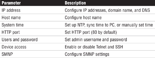
After you attach to the UC500, you will probably want to change some of the default settings. You can access the core settings by choosing Configure > Device Properties, as shown in Figure 15.1.
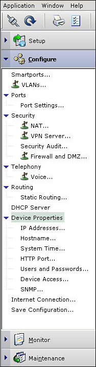
As you can see from Figure 15.1, you can set a number of parameters in this area. Each is listed in Table 15.1.
There are two graphical views you can access from within CCA:
![]() The topology view, which presents a topological representation of the Cisco devices that CCA is aware of
The topology view, which presents a topological representation of the Cisco devices that CCA is aware of
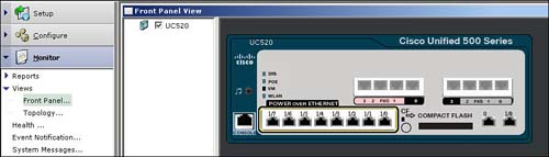
![]() A graphical view of the front panel of the UC500
A graphical view of the front panel of the UC500
The topology view is created from the information that the CCA learns from Cisco Discovery Protocol (CDP). CDP is a Cisco-proprietary protocol that is used to share information about other Cisco devices. From this view, you can right-click the devices shown and configuration options appear. The options that are available depend on the device you have selected.
Figure 15.2 shows the graphical view of the front of a UC500. From this view, you can see which ports are installed in the UC500 and view the status of the PoE ports. You can also configure the settings such as speed, duplex, and power of the PoE ports by right-clicking one and selecting Port Settings.
CCA allows you to easily upgrade the system files without having to access the command-line interface (CLI). Choose Maintenance > Software Upgrade. A screen appears that shows the version of the Cisco IOS Software currently installed. To upgrade the IOS version, click the Upgrade Status button. A small window appears that prompts you for the name of the image file you want to upgrade to. Click the Browse button and navigate to the location on your PC in which the file is stored.
The UC500 has two operating systems, the Cisco IOS and the Cisco Unity Express OS. When using CCA to upgrade the system files, you can choose to upgrade one or both of these. If you choose to upgrade both, you need to make sure that the .zip file you select contains both sets of required files. The language selection is used for Unity Express, and additional languages can be downloaded from Cisco.com. Click OK to begin the upgrade. You can click the Status button in the Software Upgrade window to monitor the progress of the upgrade.
CCA can also assist you in maintaining the files in the UC500 flash. To view the files that are in flash, choose Maintenance > File Management. In the new window that appears, click the files tab and then click the arrow that is next to flash. The flash memory content is displayed. You can delete files from flash by selecting the Delete check box next to the file you want to remove and clicking Apply or OK.
New files can be copied to flash using the drag-and-drop method. To do this, simply drag a file from your PC and place it on the UC500 on the topology view. You will be prompted to confirm that you want to copy the file. Select Upload and the file will be uploaded to flash. The previous topic, upgrading, explains how to upgrade the IOS using the Software Upgrade feature. You can also use this drag-and-drop method to upload a new IOS to flash.
One of the most important parts of the CCA in terms of the exam is the voice configuration area. Because you need to be familiar with the graphical interface, a figure showing each screen and a definition for each parameter that appears on the screen are provided. To begin voice configuration, choose Configure > Telephony > Voice.
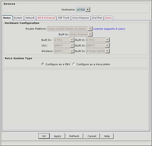
The first area of configuration is Device. The majority of the information found on the Device screen is automatically populated based on what CCA learned during its discovery phase. CCA uses CDP to identify and map directly connected neighbors, such as an external Cisco switch, and add them to the device list and topology view. In Figure 15.3, you see that CCA learned that the device is a UC520 with Unity Express with four Foreign Exchange Station (FXS) ports, four Foreign Exchange Office (FXO) ports, and eight switch ports built in. All other slots in this device are empty. You need to determine whether to configure the voice system to operate in private branch exchange (PBX) or keysystem mode.
Exam Alert
PBX mode is the default. In this configuration, incoming calls are routed to an Auto Attendant or operator and then routed to the desired party. In the keysystem mode, most phones are configured the same, and incoming calls can be answered on any phone.
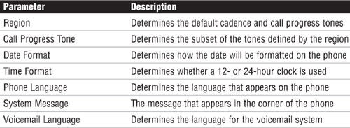
The System configuration screen is used to configure locale settings and speed dials. In Figure 15.4, you see all the parameters that you can configure from this screen. Table 15.2 briefly defines each parameter.
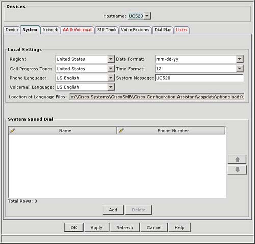
The location of the language files also appears on this screen as do speed dials that are configured on this system. To add a speed dial, click the Add button at the bottom of this screen. A row will be added in the System Speed Dial box. Enter the name and number in the row and click Apply.
The Network section is where you configure IP and VLAN information. In Figure 15.5, you can see the various parameters that need to be configured.
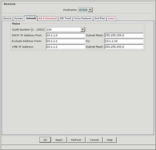
The first parameter is the VLAN Number. Select the VLAN that is going to be used for voice, that is, the voice VLAN. The DHCP IP Address Pool, Subnet Mask, Excluded Address From, and Excluded Address To parameters allow you to configure a DHCP pool for the voice VLAN. The IP address and subnet mask define the scope of all available subnet addresses, and the exclusion range blocks IP addresses within that range from being assigned to end devices.
Make sure that the IP address and subnet mask of the interface that will be servicing SCCP requests are configured and operational.
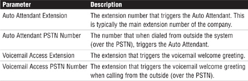
This section describes the AA & Voicemail tab. In Figure 15.6, you see that there are 16 fields that can be configured here, but by default, only four are required. Table 15.3 offers a description of these four fields.
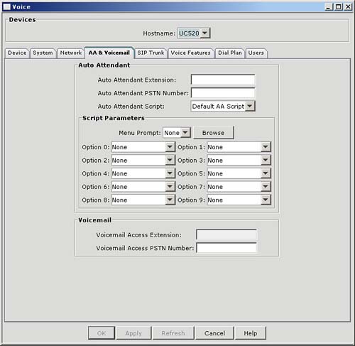
In addition to these four parameters, there are also script-related parameters. If the default script is selected for the Auto Attendant, these parameters are not used. However, if you choose to use a script other than the default, you might need to configure these additional parameters.
To select a script, click the down arrow on the Auto Attendant Script drop-down box and select the desired script. When a nondefault script is selected, the script parameters will be accessible. Select the audio file that you want to play when the Auto Attendant answers from the Menu Prompt drop-down box. The 10 Option parameters (labeled Option 0 through Option 9) allow you to configure where a call is transferred to when a user presses a touchtone during the greeting. You can select an extension from the drop-down list or simply type in the desired extension.
If you are using a SIP trunk, you need to configure the SIP trunk parameters. Figure 15.7 shows the SIP trunk configuration page.
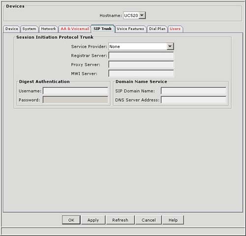
When configuring a SIP trunk, select the service provider from the Service Provider drop-down list. This list has three choices: AT&T, Cbeyond Communications, and Generic SIP Trunk Provider. The service provider will provide you with the information for the rest of the fields on the screen. In some cases, the service provider might not require all parameters to be configured. Keep in mind that SIP trunks are not supported when the system is configured in keysystem mode.
The Voice Features section is where you configure features such as paging and hunt groups. In Figure 15.8, you can see that nine features can be configured here. However, when configured in keysystem mode, only intercom and paging can be configured on this page. Let’s look at each feature individually.
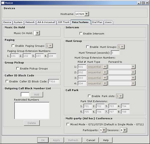
The Music on Hold (MOH) feature is simple to configure. From the drop-down list, select the audio source file you want to use for MOH. The file must be in the flash on the UC500 for it to appear in this list. Use this feature when there is no external MOH source connected to the UC500.
By default, paging is disabled. To enable paging, select the Enable Paging Groups check box. You can configure up to four paging groups with three directory numbers (DNs) each from this page. Select the paging group number from the Paging Group drop-down list, and then enter the DNs under the Paging Group Extension Numbers label.
Group Pickup allows one person in an office to enter a code on her phone and answer someone else’s phone in the same pickup group. To enable Group Pickup, select the Enable Pickup Groups check box. Up to eight pickup groups can be configured.
The Caller ID Block Code feature allows the user to dial a number that starts with a star (*) before dialing the destination number to block his caller ID. To enable this feature, select the Enable check box and enter the code in the Caller ID Block Code field. The code should be four digits, starting with a *.
You can configure numbers that you do not want internal calls to be able to dial. This is accomplished by adding the numbers to the outgoing call block number list. To add a number, enter it in the field to the left of the Add button and then click the Add button. The numbers you add will appear in the Restricted Numbers box.
You can configure up to four hunt groups from this screen. To configure a hunt group, select the Enable check box and select the number of hunt groups you want to configure from the Hunt Groups drop-down list. Configure the Hunt Timeout value, which determines the number of seconds each DN in the group will ring. Now configure the pilot number for each hunt group. The pilot is the number of the first DN in the hunt group. This is the number that will be dialed to reach this hunt group. Now configure the hunt type.
Exam Alert
There are three hunt types:
Sequential: The call is sent to the first DN in the hunt group. If that DN does not answer, the call is forwarded to all other DNs in the order they appear in the hunt group.
Longest Idle: The call is routed to the DN that has been idle the longest.
Peer: The call is routed to the DN in the hunt group that follows the DN that answered the last call (round robin).
You can configure up to eight call park numbers from this screen. To configure call park numbers, select the Enable check box and select the number of call park numbers you want to configure from the Park Slots drop-down list. Now simply enter the numbers you want to use as call park numbers in the Park Slot Extensions fields.
By default, eight ad hoc conferences with three participants are supported. All three calls must be G.711 or G.729. To have more participants or to run mixed mode (G.711 and G.729) with more than three participants, you must have available digital signal processor (DSP) resources. If DSPs are available, you can increase the number of conference participants using both G.711 and G.729 codecs.
The Dial Plan section allows you to define the following:
![]() Number of Digits Per Extension: Determines the number of digits an extension will be. The default is three.
Number of Digits Per Extension: Determines the number of digits an extension will be. The default is three.
![]() Outgoing Call Dial Plan Locale: Determines whether the North America dial plan will be used. If so, the most common settings are predefined. When Other is chosen, no predefined settings exist.
Outgoing Call Dial Plan Locale: Determines whether the North America dial plan will be used. If so, the most common settings are predefined. When Other is chosen, no predefined settings exist.
![]() Number of Digits in Area Code: Determines the length of the area code for the country that the system is installed in.
Number of Digits in Area Code: Determines the length of the area code for the country that the system is installed in.
![]() Number of Digits in Local Number: Determines the number of digits for a local call in the country that the system is installed in.
Number of Digits in Local Number: Determines the number of digits for a local call in the country that the system is installed in.
![]() Digits for Placing Long Distance Call: Determines the digits that must be dialed when placing a long-distance call.
Digits for Placing Long Distance Call: Determines the digits that must be dialed when placing a long-distance call.
![]() Digits for Placing International Call: Determines the digits that must be dialed when placing an international long-distance call.
Digits for Placing International Call: Determines the digits that must be dialed when placing an international long-distance call.
![]() Access Code: Determines the number that must be dialed to place an outbound call.
Access Code: Determines the number that must be dialed to place an outbound call.
![]() Emergency Numbers: Determines the number that can be dialed for emergency service in the country in which the system is installed.
Emergency Numbers: Determines the number that can be dialed for emergency service in the country in which the system is installed.
![]() FXO Trunks: Determines when inbound FXO calls are sent. The choices are Operator, Hunt Group, and Custom Configuration. If Operator is selected, enter the operator extension. If Hunt Group is selected, choose the appropriate hunt group from a drop-down list. If Custom Configuration is selected, configure the destination number for each port.
FXO Trunks: Determines when inbound FXO calls are sent. The choices are Operator, Hunt Group, and Custom Configuration. If Operator is selected, enter the operator extension. If Hunt Group is selected, choose the appropriate hunt group from a drop-down list. If Custom Configuration is selected, configure the destination number for each port.
![]() Direct Inward Dial: You can configure mapping for Direct Inward Dial (DID) by clicking the Configure button. You can then configure one-to-one DID translations or many-to-one DID translations.
Direct Inward Dial: You can configure mapping for Direct Inward Dial (DID) by clicking the Configure button. You can then configure one-to-one DID translations or many-to-one DID translations.
The Users section not only allows you to create users but also phones as well. In Figure 15.9, you see the 7971 phone with extension 2001 assigned to user Helen Costew.
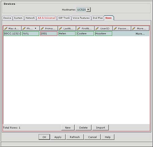
To add a phone, click the New button. This adds a line below the last phone listed with a MAC address of all 0s. Enter the MAC address of the phone in the first field. From the drop-down list in the second field, select the phone model. Enter the primary DN in the next field. Enter the last and first name in the fourth and fifth fields and the user ID in the sixth field. The password should be entered in the next field. The last field is a link to phone-specific configuration. Depending on what type of phone you are adding, you can configure such things as button settings, forwarding, intercom, pickup groups, and so on.
In the Configuration section of CCA, you can access the port, security, and wireless settings.
To access the Ethernet port settings, choose Configure > Ports > Port Settings, as shown in Figure 15.10.
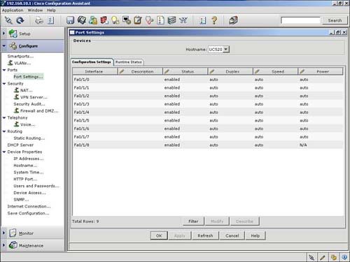
Figure 15.11 shows the Port Configuration Settings screen. You can use this screen to review physical connectivity.
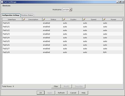
Figure 15.12 shows the Runtime Status screen. You can use this screen to review the PoE power consumption.
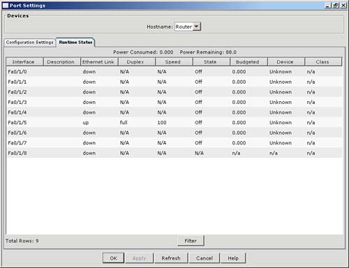
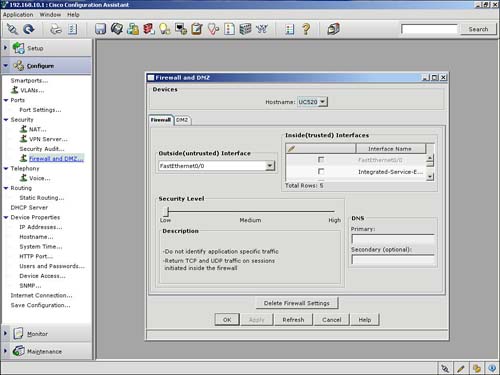
Figure 15.13 provides an overview of the Security section of CCA, where the administrator can define Network Address Translation (NAT), VPN server for remote access, and firewall and DMZ settings.
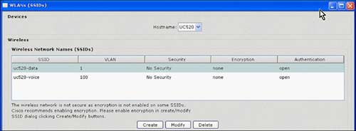
SBCS supports wireless connectivity for small businesses, and you should treat voice and data services similarly to LAN connectivity. Implement a wireless VLAN (WVLAN) for data and a separate WVLAN for voice. Make sure to create the VLANs before configuring the WVLANs. Figure 15.14 shows an example of data and voice WVLANs.
Routing is typically not a major issue with an SBCS installation because all networks terminate at the router component. To connect to the Internet, you need to create a static route that directs all unknown IP addresses, except for RFC 1918 private addresses, to the Internet interface. No dynamic routing protocols are supported.
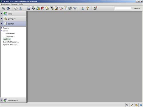
CCA does not just configure the SBCS; it can also monitor both internal and external resources. Figure 15.15 shows the menu location on CCA that provides access to Health, Event Notification, and System Messages.
After the installation is complete, the SBCS should run for years with no trouble. As system features and phones are added, the SBCS could be taxed to provide the same level of service that the users received after the initial installation. Use the tools described in the following sections to monitor the effectiveness, identify critical events, and note system information messages.
Figure 15.16 provides a look at the six standard graphical displays used to monitor SBCS: Bandwidth Utilization, Packet Error Rate, PoE Utilization, Temperature, CPU Utilization, and Memory Utilization.

With CCA active on the management PC, system events will generate a pop-up window showing the list of new events. Clicking one of the pop-up events takes you to the Event Notification screen.
Figure 15.17 displays a mechanism for reviewing and acknowledging all events that the UC500 and its associated devices generate during normal and failed conditions.
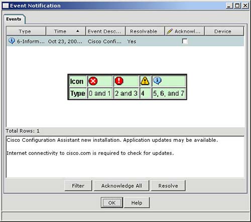
There are four categories of event types that are identified by unique icons, and each event type is matched to standard syslog levels as follows:
![]() Critical error: Syslog level (type) 0 and 1 events are identified with a red circled X icon.
Critical error: Syslog level (type) 0 and 1 events are identified with a red circled X icon.
![]() Error: Syslog level (type) 2 and 3 events are identified with a red circled exclamation point icon.
Error: Syslog level (type) 2 and 3 events are identified with a red circled exclamation point icon.
![]() Warning: Syslog level (type) 4 events are identified by the exclamation point within a yellow triangle icon.
Warning: Syslog level (type) 4 events are identified by the exclamation point within a yellow triangle icon.
![]() Informational: Syslog level (type) 5, 6, and 7 events are identified by the blue i bubble icon.
Informational: Syslog level (type) 5, 6, and 7 events are identified by the blue i bubble icon.
Always take care of the more critical errors and then go back to review and acknowledge the warnings and information messages.
Rather than maintaining an active Telnet or Secure Shell (SSH) connection to the UC500, the CCA provides a mechanism to view or save the current console message output. Figure 15.18 shows an example of the System Messages screen.

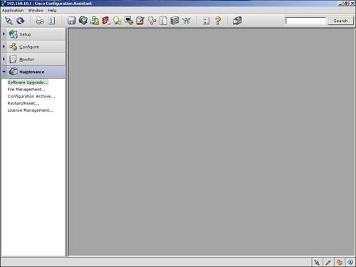
The following sections cover several maintenance options for SBCS. Figure 15.19 shows the following five functions: Software Upgrade, File Management, Configuration Archive, Restart/Reset, and License Management.
CCA allows you to easily upgrade the system files without having to access the command-line interface (CLI). The current version of IOS can be found by choosing Maintenance > Software Upgrade. A line appears that shows the name of the IOS that is currently installed. To upgrade the operating systems, click the Upgrade Settings button. A small window appears that prompts you for the name of the upgrade image file. Click the Browse button and navigate to the location on your PC in which the file is stored. See Figure 15.20 for a sample of this process.
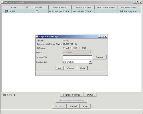
The UC500 has two operating systems, the Cisco IOS and the Cisco Unity Express (CUE) OS. When using CCA to upgrade the system files, you can choose to upgrade one or both of these. If you choose to upgrade both, make sure that the .zip file you select contains both sets of required files. The language selection is used for Unity Express and additional languages must be downloaded from Cisco.com as required and added to the .zip file. Click OK to begin the upgrade. You can click the Status button in the Software Upgrade window to monitor the progress of the upgrade.
Don’t forget the other option, which is to copy and paste the updated .zip file from your PC to the device icon in the topological view.
Exam Alert
There are two methods to upgrade operating system files on the SBCS: drag and drop a .zip file onto the topological view icon or choose Maintenance > Software Upgrade at the CCA graphical user interface (GUI).
When upgrading, there are three upgrade choices: just UC500, just CUE, or both.
In the Maintenance section of CCA, you can back up and restore device configurations. Cisco Unified Communications Manager Express configurations can be backed up without service interruption. Cisco Unity Express backups are always performed by taking voicemail and Auto Attendant services offline. Restores are performed offline for both call processing and voicemail. Figure 15.21 shows the backup screen, where the most important entry is the backup note. This can be used to clearly identify the “what, when, and why” backup information.
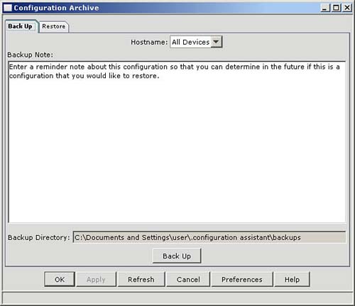
Individual device backups or all devices can be associated with a specific backup job, so documentation of the contents is important. Backup filenames are built from the host name, date and time, and MAC address for easier identification.
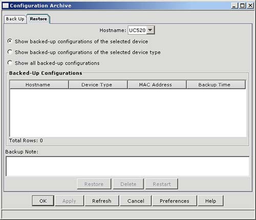
The backup screen allows you to scan restore files for the specific device, the specific device type, or all backed up configurations, as shown in Figure 15.22.
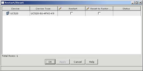
If you need to clear an existing SBCS to go back to the initial factory defaults, select the Reset to Factory Default check box in the Maintenance > Restart/Rest section, as shown in Figure 15.23.
|
1. |
A. DHCP is enabled by default. The following answers are incorrect: B (actual default password is cisco), C (actual default IP address is 192.168.1.1), and D (actual default SSIDs are uc520-data and uc520-voice). |
|
2. |
B. Create a |
|
3. |
A and B. PBX mode is the default, and calls can be routed to an attendant or Auto Attendant. Answer C is incorrect because most phones are configured the same in keysystem mode, not PBX mode. Answer D is wrong because PBX mode has nothing to do with integrating to a PBX. |
|
4. |
E. You cannot use SIP trunks when UC500 systems are configured in keysystem mode. Answers A, B, C, and D are incorrect for the same reason. |
|
5. |
A. Sequential hunting hunts sequentially down the list of directory numbers. Answer B is incorrect because sequential hunting does not use idle time. Answer C is incorrect because sequential hunting does not send the call to the least recently used DN. Answer D is incorrect because sequential hunting does not send the call to DNs in a random order. |
|
6. |
A, B, and E. These are device security features. Answers C and D are about communications security, not device security. Answer F is used to secure PCs. |
|
7. |
C. Six health-monitoring graphs are provided by default. Answers A, B, and D list incorrect values. |
|
8. |
A, B, and E. UC500 only, Cisco Unity Express only, or both components. Answers C and D are for devices not supported by CCA; therefore answer F, all devices, is incorrect. |
|
9. |
D. This answer correctly maps the syslog levels 0 to 7 to the four event icons used in Cisco Configuration Assistant, and answers A, B, and C are incorrect. |
|
10. |
C. This answer correctly identifies the process for backing up the UC500 platform. Answer A is not a valid CLI command. Answers B and D require Windows networking support, which is not a supported protocol with the UC500 series and is incorrect. |