Chapter 9. CUBE Interworking Features
This chapter covers the following topics:
• SIP–SIP Interworking: This section details call setup features and interworking involved with establishing SIP-to-SIP sessions through CUBE.
• Mid-call Signaling: This section describes the mid-call signaling that occurs and how CUBE can perform interworking actions to modify or block specific signaling exchanges observed on a given call leg.
• SIP Authentication with CUBE: This section covers the different ways CUBE can authenticate incoming SIP sessions in addition to responding to authentication requests from other SIP user agents.
• Media Interworking: This section explores the methods CUBE uses to perform interworking to multimedia streams established through CUBE.
This chapter covers the following CLACCM 300-815 exam topics:
• 1.1 Troubleshoot these elements of a SIP conversation
• 1.1.a Early media
• 1.1.b PRACK
• 1.1.c Mid-call signaling (hold/resume, call transfer, conferencing)
• 1.1.d Session timers
• 1.1.e UPDATE
• 1.2 Troubleshoot these H.323 protocol elements
• 1.2.a DTMF
• 1.2.b Call set up and tear down
• 1.3 Troubleshoot media establishment
• 3.1 Configure these Cisco Unified Border Element dial plan elements
• 3.1.a DTMF
• 3.1.c Codec preference list
• 3.2 Troubleshoot these Cisco Unified Border Element dial plan elements
• 3.2.a DTMF
• 3.2.c Codec preference list
As a session border controller (SBC), CUBE is often tasked with interworking and establishing sessions between different real-time multimedia networks. These interworking tasks range from normalizing signaling exchanges, messages, responses, and event sequencing to media encoding interworking for audio, video, and DTMF. The need for CUBE interworking features often arises due to vendor interoperability. Although SIP is an open standard defined by numerous Requests for Comments (RFCs), not all vendors support the full range of SIP RFCs. In addition, some vendor equipment and endpoints expect very specific signaling exchanges to occur, and a slight deviation from that baseline signaling exchange could cause call failures or media issues. As a result of these needs, CUBE Enterprise contains a variety of interoperability features that enable Unified CM administrators to exert control over sessions established through CUBE to perform the required interoperability actions for both signaling and the media. This chapter covers the most common interworking features used with CUBE deployed in Unified Collaboration (UC) environments around the world. This chapter also provides configuration examples and debugging samples to further illustrate the topic.
“Do I Know This Already?” Quiz
The “Do I Know This Already?” quiz allows you to assess whether you should read the entire chapter. If you miss no more than one of these self-assessment questions, you might want to move ahead to the “Exam Preparation Tasks” section of the chapter. Table 9-1 lists the major headings in this chapter and the “Do I Know This Already?” quiz questions related to the material in each of those sections to help you assess your knowledge of these specific areas. The answers to the “Do I Know This Already?” quiz appear in Appendix A, “Answers to the ‘Do I Know This Already?’ Quiz Questions.”
Table 9-1 “Do I Know This Already?” Foundation Topics Section-to-Question Mapping

1. Which command is required to instruct CUBE to always send early offer on the outbound call leg, regardless of the inbound call leg’s offer type?
a. delayed-offer disable
b. voice-class sip eo
c. early-offer forced
d. pass-thru content sdp
2. Which SIP provisional responses indicate that in-band audio, such as ringback, will be streamed to CUBE through an audio channel? (Choose two.)
a. 183 Session in Progress without SDP
b. 183 Session in Progress with SDP
c. 180 Ringing without SDP
d. 180 Ringing with SDP
3. Which SDP parameters can be used by a SIP user agent in a re-INVITE message to signal a call hold? (Choose three.)
a. a=sendrecv
b. a=sendonly
c. a=inactive
d. c=IN IP4 0.0.0.0
e. a=rtpmap:0 PCMU/8000
4. Which SIP header field is referenced by CUBE attempting to interwork a SIP REFER when configured for REFER consumption?
a. Referred-by
b. To
c. Request-uri
d. Refer-to
5. Which transfer type in Unified CM allows an IP phone user to open a media channel with the transfer target first and have a conversation before completing the transfer?
a. Blind transfer
b. Unattended transfer
c. Consult transfer
d. Refer transfer
6. What perquisite exists before an UPDATE message with SDP can be sent to change media parameters on a call that has not yet been answered with a 200 OK + SDP?
a. None. This is impossible.
b. 183 Session in Progress must be present.
c. A PRACK handshake must be completed successfully.
d. Early offer must be enabled on CUBE.
7. By default, when CUBE receives a SIP packet from an untrusted source, what action is taken?
a. CUBE sends a 403 Forbidden.
b. CUBE trusts all IP addresses and routes the call.
c. CUBE drops the packet.
d. CUBE sends a 503 Service Unavailable.
8. Which types of addresses can be configured on CUBE by the IP trusted list feature? (Choose two.)
a. IPv4
b. IPv6
c. Domain names
d. Phone numbers
9. What is the default codec for a SIP VoIP dial peer?
a. g729br8
b. g729r8
c. g711ulaw
d. g711alaw
10. Which command should be used to disable video calls on CUBE?
a. no video codec
b. audio forced
c. codec g711ulaw
d. no vad
11. When configuring DTMF relay interworking on CUBE, which command allows CUBE to negotiate different RTP payload types, such as reception of RTP-NTE PT 100 and sending of RTP-NTE PT 101?
a. asymmetric payload dtmf
b. rtp payload-type nte 101
c. pass-thru content sdp
d. early-offer forced
Foundation Topics
SIP–SIP Interworking
The most common CUBE deployment uses SIP as the signaling protocol to connect different networks. In this type of scenario, CUBE acts as a back-to-back user agent (B2BUA). As a B2BUA, CUBE has collocated user agent client (UAC) and user agent server (UAS) functionality. This is very useful for SIP interworking as it allows the SBC to receive and send SIP messages from either perspective during a session. The B2BUA can maintain two separate SIP dialogs and interwork any events that occur on one dialog with the participant of the other dialog and vice versa.
The following sections cover the many different interworking options available for SIP–SIP SBCs.
Early Offer and Delayed Offer Interworking
Chapter 2, “VoIP Protocols: SIP and H.323,” discusses early offer and delayed offer. As you learned there, the inclusion of media parameters and SDP within a UAC’s initial INVITE message determines whether the call is early offer. A call is considered early offer when the INVITE message sent from the UAC contains SDP, and the UAS usually replies with a response that contains an answer. In most scenarios, this answer is in the UAS’s 200 OK response. In contrast, with delayed offer, the UAS’s 200 OK contains the SDP offer, and the ACK from the UAC contains the answer SDP. Most Unified CM devices support either type of offer and can generate an answer accordingly. However, some services require early offer support in order to cut through service messages and ringback tones toward the calling party. In addition, some devices only signal delayed offer.
As a result of these varying requirements, CUBE must be able to interwork delayed offer and early offer during session establishment so that the offer/answer is completed properly on all legs of a call. Normally, when sending an offer, CUBE mirrors the type of offer received on the ingress call leg. That is, if CUBE receives an early offer INVITE message, it sends an early offer INVITE message to the peer call leg. Similarly, if CUBE receives a delayed offer INVITE message, it sends a delayed offer INVITE message to the peer call leg. For scenarios where early offer is required on the outbound call leg and delayed offer is required on the inbound call leg, CUBE’s default behavior can be modified to ensure that early offer is always sent on the outbound call leg. Example 9-1 shows how to modify this behavior on CUBE in order to always send early offer.
Tip
CUBE cannot send delayed offer on an outbound call leg if early offer is received on the inbound call leg. Early offer is always sent in this scenario.
![]()
Example 9-1 Forcing Early Offer Globally
! Global Configuration
voice service voip
 sip
early-offer forced
! or
! Per Dial-peer
dial-peer voice 1 voip
voice-class sip early-offer forced
!
Note
Examples in this chapter include both global configuration and dial peer–specific configuration to show both CLI syntax. As a refresher, remember the order of operations for voice configurations in IOS. The configuration found on the inbound and outbound dial peer used during a session always supersede any other configuration. If no dial peer–specific configuration exists, any voice class tenant configuration applied to an inbound or outbound dial peer used during a session is used. Finally, if no dial peer–specific or voice class tenant configuration exist, the global configuration in the voice service voip or sip-ua commands is leveraged.
Reliable Handling and Interworking of Provisional Responses
A provisional response acknowledgement, better known as a PRACK, is a SIP request used to reliably confirm the receipt of a provisional 1xx-level response. PRACK is defined in RFC 3262 as a way to mirror the reliability seen with INVITE, 200 OK, and ACK. Some Internet telephony service providers (ITSPs) and other devices require a PRACK exchange before cutting through ringback or service messages. In addition, some SIP RFCs indicate that specific signaling exchanges cannot be completed unless a reliable message exchange involving PRACK has occurred. This chapter details one such scenario.
Take, for example, the scenario outlined in Figure 9-1, in which a UAC has sent an early offer INVITE to an upstream UAS, and there are many different network hops in between. This UAS sends an 18x message with SDP to the UAC, with the intent that it will be sending media to the UAC. Due to some unforeseen circumstances, the 18x message is dropped in transit across one of the network hops and does not make it to the UAC. The UAS does not know that this was dropped and begins sending packets to the UAC. From the perspective of the UAC, which did not receive the 18x message, these packets may be dropped as they are not part of the SIP current dialog. Had the 18x message been sent with reliability in mind, the UAS would know for sure if the 18x was received and processed by the UAC.

Figure 9-1 Unreliable Provisional Response Across Different Network Hops
A UAC advertises the ability to support PRACK by including the tag 100rel in the Supported header of a SIP INVITE message (see Example 9-2). RFC 3262 dictates that the only SIP request type that can advertise support for PRACK is a SIP INVITE message. In addition, the use of advertising support for PRACK in a re-INVITE message is not often seen because mid-call re-INVITE messages rarely have provisional responses, which would require the use of reliability. Finally, in addition to having a Supported header, a UAC may also advertise PRACK support and necessity by sending the 100rel tag in the Require header.
Example 9-2 Sample INVITE Message with PRACK Support
INVITE sip:[email protected]:5060 SIP/2.0
Via: SIP/2.0/TCP 172.18.110.48:5060;branch=z9hG4bK3a34b28097e
From: <sip:[email protected]>;tag=22968~1992ce86-77ac-43a7-91b7-90778966a9f5-30207629
To: <sip:[email protected]>
Call-ID: [email protected]
Supported: 100rel,timer,resource-priority,replaces
Min-SE:  1800
Allow: INVITE, OPTIONS, INFO, BYE, CANCEL, ACK, PRACK, UPDATE, REFER, SUBSCRIBE, NOTIFY
CSeq: 101 INVITE
Expires: 180
Session-ID: 1aaee55200105000a0000c75bd110ca4;remote=00000000000000000000000000000000
Session-Expires:  1800
Contact: <sip:[email protected]:5060;transport=tcp>
Max-Forwards: 69
Content-Length: 0
Because this UAC has advertised the ability to support PRACK, the UAS receiving this request can send a provisional response reliably if it wants to. The reception of a Supported header with 100rel does not require the UAS to send a response reliably. These items are only informing the UAS that it can send PRACK if it deems it necessary. In the same vein, a UAS cannot request a reliable response if the UAC has not advertised support for PRACK in the INVITE message. The UAC instead may send a 421 Extension Required response to the UAC, indicating that the UAS expects the UAC to support PRACK.
If the UAS wants to send a provisional response reliably, it must include the 100rel tag within the Require SIP header of the provisional response. Including this header and tag requires a PRACK from the UAC, and failure to return a PRACK indicates that the provisional response must not have been handled properly by the UAC. The UAS retransmits the provisional response to the UAC and requests PRACK to confirm reliable reception of the retransmission. If no PRACK is received for the retransmitted response, the retransmission may occur a few more times, as per the applications logic or administrative configuration. After all retries of the provisional are exhausted without a PRACK being received by the UAS, the UAS terminates the call because it does not believe the UAC has handed the provisional response properly. The message also contains an RSeq header with a numeric value for later use by the PRACK message. Example 9-3 details a 180 Ringing message sent from the UAS, requesting a reliable confirmation by the UAC.
Tip
PRACK cannot be sent for the 100 Trying response. All other numbered responses 101 through 199 can be sent reliably.
Example 9-3 A 180 Ringing Response Expecting PRACK
SIP/2.0 180 Ringing
Via: SIP/2.0/TCP 172.18.110.48:5060;branch=z9hG4bK3a34b28097e
From: <sip:[email protected]>;tag=22968~1992ce86-77ac-43a7-91b7-90778966a9f5-30207629
To: <sip:[email protected]>;tag=512A088-1C36
Call-ID: [email protected]
CSeq: 101 INVITE
Require: 100rel
RSeq: 3322
Allow: INVITE, OPTIONS, BYE, CANCEL, ACK, PRACK, UPDATE, REFER, SUBSCRIBE, NOTIFY, INFO, REGISTER
Remote-Party-ID: <sip:[email protected]>;party=called;screen=no;privacy=off
Contact: <sip:[email protected]:5060;transport=tcp>
Content-Length: 0
Upon receiving a provisional response with a Require 100rel header, the UAC must respond with a PRACK to inform the UAS of that it received the message. The PRACK message includes the RAck header, which contains the value from the RSeq header of the message, requiring reliability in addition to the method that is copied from the CSeq of that same response being acknowledged. Example 9-4 shows the PRACK sent in response to Example 9-3.
Example 9-4 Sample PRACK for the 180 Ringing Response
PRACK sip:[email protected]:5060;transport=tcp SIP/2.0
Via: SIP/2.0/TCP 172.18.110.48:5060;branch=z9hG4bK3a42384a9bf
From: <sip:[email protected]>;tag=22968~1992ce86-77ac-43a7-91b7-90778966a9f5-30207629
To: <sip:[email protected]>;tag=512A088-1C36
Call-ID: [email protected]
CSeq: 102 PRACK
RAck: 3322 101 INVITE
Max-Forwards: 70
Content-Length: 0
Upon receiving the PRACK, the UAS sends a 200 OK with the CSeq of the PRACK to confirm receipt. At this point, the PRACK process is complete, and the rest of the session establishment occurs normally. Figure 9-2 illustrates the entire PRACK exchange, starting with the first request and ending with the 200 OK.
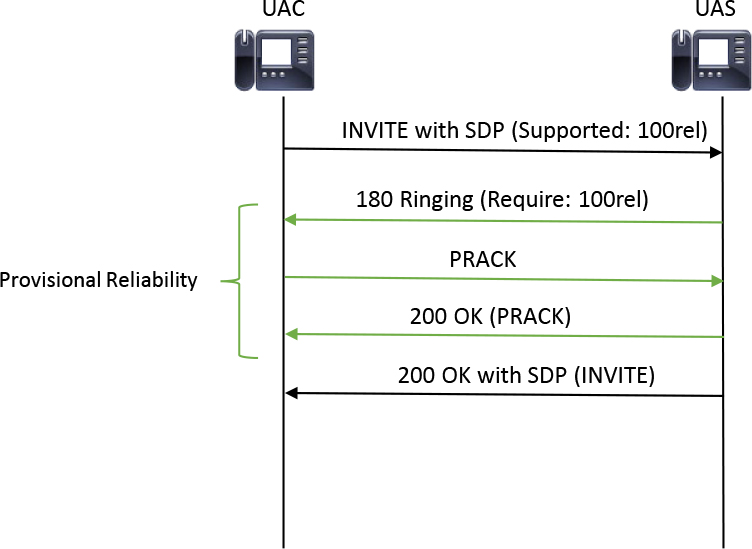
Figure 9-2 Full PRACK Exchange Between a UAC and a UAS
CUBE supports PRACK by default, without the need for configuration. If a device indicates support for reliable provisional responses through the presence of the rel1xx tag in the Supported or Required header within an INVITE message, CUBE requests reliability of provisional responses on that call leg. By default, CUBE advertises PRACK capabilities for egress SIP INVITE messages, regardless of the PRACK support on the inbound call leg. This is due to PRACK being a per–call leg mechanism, meaning that one call leg on CUBE may have a PRACK exchange occur, while the other call leg does not have a PRACK exchange. Figure 9-3 shows an example of the asynchronous nature of PRACK on CUBE.
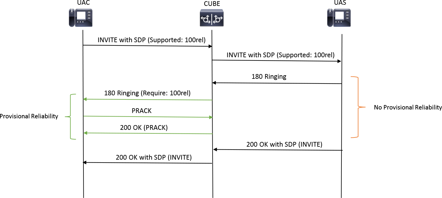
Figure 9-3 Asynchronous PRACK Exchange Across an SBC
PRACK support on CUBE can be disabled by adding the command shown in Example 9-5. Alternatively, Example 9-6 details how CUBE can be configured to require PRACK and advertise Require: 100rel in the outbound INVITE requests. The command can be returned to the default by issuing one of the commands shown in Example 9-7.
![]()
Example 9-5 Disabling PRACK Support on CUBE
! Global Configuration
voice service voip
 sip
rel1xx disable
! or
! Per Dial-peer Configuration
dial-peer voice 1 voip
voice-class sip rel1xx disable
Example 9-6 Requiring PRACK Support on CUBE
! Global Configuration
voice service voip
 sip
rel1xx require 100rel
! or
! Per Dial-peer Configuration
dial-peer voice 1 voip
voice-class sip rel1xx require 100rel
Example 9-7 Returning to the Default PRACK Support on CUBE
voice service voip
 sip
no rel1xx
! or
voice service voip
 sip
rel1xx supported 100rel
Ringback and Provisional Response Interworking
During session establishment involving CUBE, ringback may be played from one of a few sources. The first is a remote device, usually special-purpose equipment on a service provider network or, in some rare scenarios, the end device that is being called. In this scenario, a unidirectional audio channel is established from the called party to the calling party, and ringback is played out over this channel. In this scenario, the ringback played is specific to the country of the device providing ringback through the established audio channel. Figure 9-4 illustrates a remote device such as the ITSP playing ringback to the SBC and calling party.
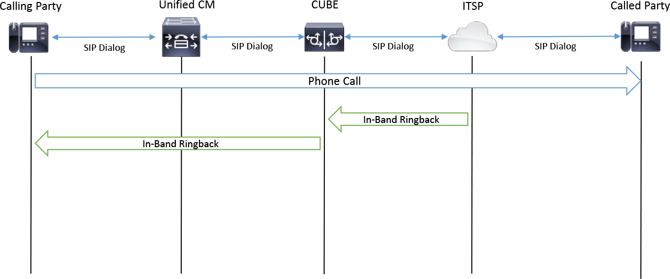
Figure 9-4 Ringback Generated from Special Provider Equipment
The second method for generating ringback is for the called device to signal the inability to play ringback to the SBC. This indication is usually achieved via the absence of media capabilities in the UAS’s response, so that early media channels do not open. When CUBE receives this type of message, it is passed through to the peer call leg because CUBE does not have the ability to generate in-band ringback on behalf of another device. Similarly, Unified CM does not have the ability to generate in-band ringback in this scenario. As a result, Unified CM sends this response to the IP phone, which plays the local ringback. Figure 9-5 shows this scenario, with the IP phone playing ringback.

Figure 9-5 Ringback Generated Locally by the IP Phone
In the context of a SIP call, call alerting (with the called party in the ringing state) is signaled using the SIP 180 Ringing or 183 Session Progress provisional responses. When a call is attempted, it may take the called party several seconds—or maybe even a few minutes—to answer the call. Before the call is connected, the called party may choose to send either zero, one, or more provisional responses. The 18x (180 or 183) provisional responses serve as an indication to play in-band audio, such as a ringback tone, to the calling party. The specific type of the 18x provisional response usually indicates the source of the ringback tone.
A 180 Ringing response is sent by the called party or a device that is negotiating call setup on behalf of the called party (for example, an IP PBX local to the called party) to indicate the inability or lack of intent to stream in-band ringback and that another device should play a locally generated ringback tone. On the other hand, a 183 Session Progress response is sent by the called party or a device that is negotiating call setup on behalf of the called party (for example, an IP PBX local to the called party) to indicate that the ringback tone will be generated in-band from the called party or special access equipment on the service provider network.
For the ringback tone to be generated from the called side, two conditions must be met:
• An audio channel from the called party to the calling party must be established.
• Information must be provided about the IP address and port pair on which the calling party is expecting to receive media.
The first condition is fulfilled by the called party, including an SDP body in the 183 Session Progress response. The second condition is met only when the SDP body encoding the media characteristics of the calling party is made available. If an early offer call is sent and a 183 with SDP is received, then early media can be cut through for ringback. If a delayed offer call is sent and a 183 with SDP is received, then a PRACK with SDP should be exchanged to enable early media ringback and audio session establishment for ringback. Note that in order for this scenario to occur, Unified CM and CUBE must both be configured for PRACK and 100rel support. Chapter 5, “Unified CM SIP Trunk Configuration,” details how to enable PRACK for Unified CM SIP trunks. If PRACK is not configured and Unified CM sends a delayed offer INVITE and receives a 183 with SDP, Unified CM converts the 18x with SDP into a 180 Ringing without SDP and sends it to the IP phone to play local ringback.
Figure 9-6 illustrates the different permutations of 183 with SDP and early and delayed offer.
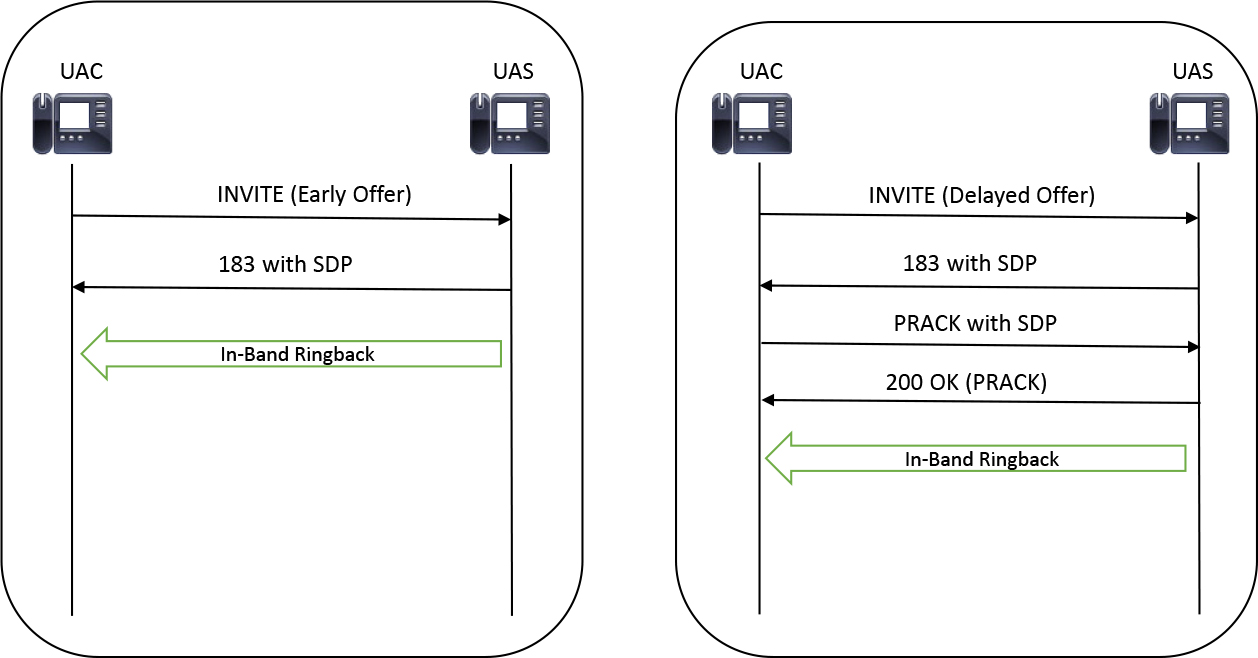
Figure 9-6 Sample In-Band Ringback Scenarios Between a UAC and a UAS
A problem arises because RFC 3261 does not define which 18x responses should contain SDP. Although this is not defined, it is normal to see a 183 with SDP for in-band ringback and use the 180 Ringing message without SDP to signal the inability or lack of intent to play in-band ringback. In rare circumstances, a 180 with SDP or a 183 without SDP may be observed. Thus, it is generally accepted that a device is attempting to establish an audio channel for ringback if it sends either 18x message with SDP, and the absence of SDP indicates the inability to provide ringback, in which case local ringback interworking is required.
In most scenarios, an SBC simply forwards the received 18x response from the in leg to the out leg, without the need for extra configuration. Another problem that can arise is that there may be no upper bound on how many provisional response messages can be sent during session establishment. This includes the number of duplicate provisional responses and the sending of different types of provisional responses. In addition, RFC 3261 does not set any guidelines for the handling and interpretation of multiple different types of provisional responses within the same dialog. Should an SBC place preference on a provisional response with SDP for ringback, or should it honor the first or last provisional responses received? Due to this issue, an SBC may be equipped with its own logic with regard to the handling of multiple provisional responses, including those of different types. One example of this logic would be to block, disregard, or filter specific types of provisional responses so that only specific occurrences of provisional responses are sent on the other side of the SBC. CUBE allows an administrator to define different types of 18x messages based on the presence or absence of SDP, as shown in Example 9-8. The logic of the present or absent postfix on this command is effectively stating “if SDP present” or “If SDP absent,” so a 180 Ringing with SDP could be blocked with the command block 180 sdp present.
![]()
Example 9-8 18x Blocking on CUBE
! Global Configuration
voice service voip
 sip
block {180 | 181 | 183} sdp {present | absent}
!
! Per Dial-peer Configuration
dial-peer voice 1 voip
voice-class sip block {180 | 181 | 183} sdp {present | absent}
Another example of local logic in regard to provisional response handling is changing the messages received on one call leg into another type for the egress call leg. This can be observed if CUBE receives a 180 response with SDP. This message is converted, by default, into a 183 Session in Progress with SDP unless the command send 180 sdp is enabled, as shown in Example 9-9.
Example 9-9 Enable the Sending of 180 with SDP
! Global Configuration
voice service voip
 sip
send 180 sdp
!
! Per Dial-peer Configuration
dial-peer voice 1 voip
voice-class sip send 180 sdp
Finally, in addition to blocking, modifying, or filtering specific messages, CUBE can be configured to disable early media for 18x responses containing SDP with the disable-early-media command under the sip-ua configuration, as shown in Example 9-10. Be aware that when you add this command, the UAS may not be able to successfully deliver ringback or service messages to the UAC, which may result in silence during session establishment.
Example 9-10 Disabling 180 Early Media
sip-ua
disable-early-media 180
When troubleshooting ringback issues, it is important to look at the SIP signaling exchanged in debug ccsip messages. Then you need to attempt to answer the following questions:
• What type of 18x response is received?
• Does the remote party provide in-band ringback? If so, has the early media exchange been completed successfully?
• Does the SBC properly forward this message from one call leg to another?
• If an 18x with SDP is received, is the early media session being properly opened through a valid offer/answer?
• If this session is being opened properly, does the remote device actually send RTP packets from the defined IP and port in the SDP of the 18x with SDP? (To verify this information, a packet capture can be collected and reviewed.)
• If ringback is delayed for a bit before finally being heard by the calling party, are there protocol errors, UDP retransmissions, or erroneous call hunting (which leads to delay in the signaling that is ultimately sent to the called device)? (You can best troubleshoot delays in ringback on CUBE by enabling debug ccsip messages and debug voip ccapi inout.)
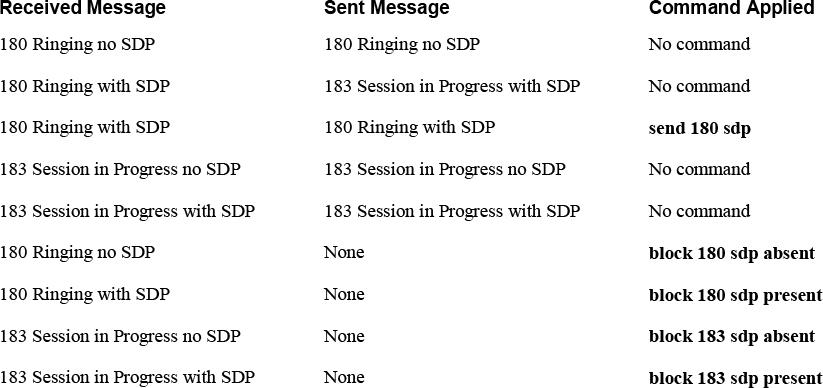
Table 9-2 can assist with troubleshooting ringback and provisional response interworking on CUBE.
![]()
Table 9-2 CUBE 18x Interworking
Mid-call Signaling
When a session is established, additional signaling exchanges may be required to maintain or modify a session. These post-session establishment messages are referred to as mid-call signaling. Mid-call signaling includes actions such as calling or called party number/name updates, modification of session media parameters, and determination of session refresh intervals. In addition to the previous signaling exchanges, mid-call signaling also includes supplementary services, such as call hold, call resume, and call transfer.
CUBE is responsible for ensuring that these mid-call signaling messages are appropriately handled on both SIP dialogs involved in a call. The following sections detail some of the most common mid-call signaling exchanges as well as how an SBC interworks the different types of mid-call signaling that can occur with these signaling exchanges.
Hold/Resume
"Let me put you on hold while I check on this item.” You frequently hear this sentence from customer care centers. What occurs in such scenarios is that one party momentarily disrupts the bidirectional flow of media by pressing a softkey or button (typically the Hold softkey) on her local device. Bidirectional flow of media is resumed when the same party presses another softkey (or the same Hold softkey) on her local device. Optionally, the held party is presented with hold music streamed from a Music on Hold server during the hold.
Because any participant in a session can place the call on hold, the terms holder and holdee are often used to define participants of a hold scenario. The holder is the participant who initiates the call hold event, and the holdee is the person being placed on hold. Placing a call on hold in most modern IP-based telephony systems typically consists of the following sequence of events:
![]()
Step 1. One party places the call on hold by pressing a softkey (such as the Hold softkey) or keying in a specific system-defined sequence of keys.
Step 2. The indication of call hold is communicated by the call control protocol over the signaling channel.
Step 3. Bidirectional flow of media is disrupted between the participants.
Step 4. Usually, when a call is placed on hold, a new media session is established between a streaming server and the holdee. This streaming server is commonly referred to as a Music on Hold (MOH) server, and it streams hold music or prerecorded announcements. Because a new media session is initiated between the holdee and the MOH server, the holdee doesn't have to listen to dead air until the call is resumed.
Step 5. When the holder is ready to resume a bidirectional media session, he presses the call Hold button or softkey or keys in a specific system-defined sequence.
Step 6. The indication to remove the call from hold and resume the communication session is communicated by the call control protocol over the signaling channel. This results in terminating the media stream between the MOH server and the holdee and creating a new media session (or reusing the previous one) between the holder and holdee.
With SIP, the endpoints involved in the call are either the holder or holdee. As an SBC, CUBE takes the role of a holder for one call leg and holdee on another call leg, although it is very rare for CUBE to initiate a hold event without first receiving a hold event from another device on a peer call leg. The main goal for CUBE is to interwork hold and resume events so that media is terminated, redirected, and reestablished properly for all parties and call legs. Failure to do this properly may result in problematic one-way audio situations, no-way audio situations, or even undesired call terminations. For the examples in this section, Unified CM takes the role of the holder and signals hold events to CUBE, which assumes the role of the holdee and ultimately interworks these events to the peer call leg. The IP phones engaged in the call are not shown for the sake of simplicity, but users of these devices would initiate the hold by pressing softkeys or buttons on the devices.
There is no explicit SIP header field that indicates call hold and call resume. Rather, SIP has to be used in concert with SDP to indicate call hold and resume. While there isn't unanimous consensus on the exact semantics of SIP and SDP for call hold and call resume, most vendors follow the guidelines of RFC 3264 and 6337. The predominant method of indicating call hold and call resume is to use SIP re-INVITE messages and to format the SDP media direction attribute (a=) and connection data information (c=) fields.
A holder can indicate desire to place a call on hold by appropriately modifying the media direction attribute (a=) or/and connection data information field (c=) of the SDP body enclosed within the SIP re-INVITE message. There are distinct ways in which a call can be placed on hold:
• A call can be placed on hold without any music.
• A call can be placed on hold such that the holdee hears hold music.
The first scenario involves the holdee hearing silence, which is commonly referred to as “dead air,” when the call is placed on hold. This is achieved when the holder sends a SIP re-INVITE message such that the direction media attribute of the SDP is set to a=inactive. As per the guidelines of RFC 3264, when the direction media attribute in the SDP offer is set to a=inactive, the SDP answer must mirror the same value of the direction attribute (that is, it must be set as a=inactive). Setting the media direction attribute to a=inactive in the offer and answer ensures that there is no media sent or received. A second method by which the holder can achieve the same outcome is by setting the connection data information field to all zeros (c=IN IP4 0.0.0.0). This not only results in suspension of any media exchange between the calling party and the called party but also results in termination of any RTCP traffic. Therefore, this alternative is not always the best. Figures 9-7 and 9-8 illustrate these alternatives for holds with no music. There are certain scenarios in which these methods are used together—that is, where the SDP of the re-INVITE message has the media direction attribute set to a=inactive and the connection data information field set to 0.0.0.0.

Figure 9-7 Hold with No Media: 0.0.0.0

Figure 9-8 Hold with No Media: a=inactive
Another scenario (see Figure 9-9), which is preferred by enterprises, involves the holdee listening to hold music or prerecorded messages for the duration of the hold sequence. This scenario is achieved when the holder sends a SIP re-INVITE message such that the media direction attribute in the SDP offer is set to a=sendonly. If the holdee sets the media direction attribute to a=recvonly in the SDP answer, a unidirectional media channel that terminates on the holdee is established. In real-world scenarios, the hold music or announcements are usually streamed from a standalone device to the holdee endpoint. Therefore, to effectively stream hold music or announcements, the holder must first tear down the media stream between itself and the holdee and establish another media stream between the MOH server and the holdee. To break the media stream, the holder might engage in an initial offer/answer exchange that sets the connection data information field to all zeros (c=IN IP4 0.0.0.0). After this, a subsequent offer/answer exchange is initiated to establish another media stream between the MOH server and the holdee. This exchange often establishes unidirectional one-way media from the MOH server to the holdee through the media direction attributes a=sendonly and a=recvonly. Figure 9-9 illustrates this process.

Figure 9-9 Hold with Unidirectional Media: a=sendonly
Note
Unified CM administrators can instruct Unified CM to send a=sendrecv and subsequently open a bidirectional media channel with the MOH server by setting the Unified CM service parameter Duplex Media Enabled to True. Although the MOH server is never expecting to receive audio, only send MOH, it may need to open a bidirectional media stream to facilitate opening pinholes when firewalls are present between the MOH server and the endpoint receiving the MOH stream.
To resume a held call, the holder must initiate another offer/answer exchange to reestablish the media stream between itself and the holdee. If hold music is being streamed, the holder may first send a re-INVITE message in an attempt to remove the media session with the MOH server and the holdee. This re-INVITE message may set the connection data information field to all zeros (c=IN IP4 0.0.0.0) and send a media direction attribute of a=inactive. Once the MOH stream has been removed, another re-INVITE message is sourced from the holder; it contains the media information of the holder and sets the media direction to a=sendrecv. The holdee returns his own media information, and if he also responds with a media direction attribute of a=sendrecv, bidirectional media is reestablished.
There is currently no standard that defines the procedures to be followed by SBCs or B2BUAs to reliably handle call hold and resume. Nonetheless, vendors of such devices must embed sufficient logic in software to ensure that such events are handled reliably, without negatively impacting the call experience. Broadly, SBCs handle call hold/resume events in one of two ways:
• Passing SIP re-INVITE message sequences end-to-end with minimal modification: SIP re-INVITE messages and responses that tear down the media stream between the holder and holdee establish a media stream between the MOH server and the holdee and reestablish the media stream between holder and holdee on call resume and passed across from the holder network to the holdee network with minimal modification. These modifications typically include overwriting the IP addresses advertised in the SIP header fields and the SDP bodies of SIP re-INVITE messages and responses. (Figure 9-11, later in this chapter, demonstrates this.)
• Abstracting hold/resume events from the holdee: The SBC completely abstracts hold/resume exchanges by the holder by handling such exchanges locally. This method may lead to interoperability issues and unexpected behavior when a peer device expects to be notified of such events. On the other hand, a peer device may not be properly equipped to handle specific types of hold/resume events, and this may result in audio problems during or after the hold/resume. Thus, this method can be employed to solve this type of interoperability issues by not advertising hold/resume events to the peer device. The benefits and drawbacks of the application of this method by an SBC are highly dependent on the peer devices’ capability sets and local network variables.
Using CUBE and Cisco Unified CM as an example, this chapter details a sample hold/resume event signaled by a Unified CM registered endpoint. Unified CM uses a mixture of the hold methods defined in the previous section when advertising a hold event. Figure 9-10 shows the topology for the following hold/resume event. Note that Unified CM also takes on the role of the MOH server for this sample session.
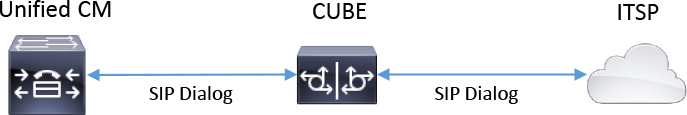
Figure 9-10 Unified CM, CUBE, and ITSP Topology
After a call is established, a user can press the Hold button or softkey on her device to initiate a hold event. Unified CM then modifies the established media stream by sending a SIP re-INVITE message with the media direction attribute set to a=inactive and the connection data information field set to c=IN IP4 0.0.0.0. Example 9-11 shows the SIP signaling for this event between CUBE and Unified CM. CUBE forwards the re-INVITE message for modifying the media stream to the peer call leg and waits for a response on that call leg before sending an answer to Unified CM. After a response is received on the peer call leg, CUBE answers the re-INIVTE message with a 200 OK message that contains the media direction attribute a=inactive as an answer to the re-INVITE offer, but CUBE chooses to send its local IP address rather than respond with c=IN IP4 0.0.0.0 in both the global and local connection data information SDP lines.
Example 9-11 Signaling with Audio Set to Inactive and 0.0.0.0 Advertised
Received:
INVITE sip:[email protected]:5060;transport=tcp SIP/2.0
CSeq: 102 INVITE
[...Truncated for Brevity...]
v=0
o=CiscoSystemsCCM-SIP 25337 2 IN IP4 172.18.110.48
s=SIP Call
c=IN IP4 0.0.0.0
b=TIAS:64000
b=AS:64
t=0 0
m=audio 22018 RTP/AVP 0 101
a=rtpmap:0 PCMU/8000
a=inactive
a=rtpmap:101 telephone-event/8000
a=fmtp:101 0-15

[...The same information occurs on the other call leg...]

Sent:
SIP/2.0 200 OK
CSeq: 102 INVITE
[...Truncated for Brevity...]
v=0
o=CiscoSystemsSIP-GW-UserAgent 5020 5458 IN IP4 172.18.110.58
s=SIP Call
c=IN IP4 172.18.110.58
t=0 0
m=audio 8066 RTP/AVP 0 101
c=IN IP4 172.18.110.58
a=inactive
a=rtpmap:0 PCMU/8000
a=rtpmap:101 telephone-event/8000
a=fmtp:101 0-16
After the media stream is successfully disabled through the SDP offer/answer exchange end to end, Unified CM sends a delayed offer re-INVITE message soliciting the SBC and, ultimately, the holdee for its media capabilities (which are subsequently encoded in the 200 OK response). After receiving the peer SDP, Unified CM sends an ACK with SDP with the media direction attribute set to a=sendonly and the connection data information encoding the IP address of a MOH server. Example 9-12 shows the delayed offer exchange between Unified CM and CUBE for MOH insertion. (MOH is covered later in this chapter.) Again, this SIP transaction takes place end to end. When this SIP transaction concludes, the call is on hold, and the holdee hears hold music audio. This continues until the user desires to take the call off hold. In addition, because the MOH media resource does not need to receive media but only send media, Unified CM allocates a dummy port of 4000 for sourcing media from the MOH resource.
Example 9-12 Negotiating Unicast MOH
Sent:
SIP/2.0 200 OK
CSeq: 103 INVITE
[...Truncated for Brevity...]
v=0
o=CiscoSystemsSIP-GW-UserAgent 5020 5459 IN IP4 172.18.110.58
s=SIP Call
c=IN IP4 172.18.110.58
t=0 0
m=audio 8066 RTP/AVP 0 101 19
c=IN IP4 172.18.110.58
a=rtpmap:0 PCMU/8000
a=rtpmap:101 telephone-event/8000
a=fmtp:101 0-16
a=ptime:20

Received:
ACK sip:[email protected]:5060;transport=tcp SIP/2.0
CSeq: 103 ACK
[...Truncated for Brevity...]
v=0
o=CiscoSystemsCCM-SIP 25337 3 IN IP4 172.18.110.48
s=SIP Call
c=IN IP4 172.18.110.48
t=0 0
m=audio 4000 RTP/AVP 0
a=X-cisco-media:umoh
a=ptime:20
a=rtpmap:0 PCMU/8000
a=sendonly
When the end user is ready to take the call off hold, he presses the button or softkey again to resume the call; Unified CM sends another re-INVITE message with the media direction attribute set to a=inactive and the connection data information field set to 0.0.0.0. This results in the de-allocation of the media resource for MOH. Finally, Unified CM sends a delayed offer re-INIVTE message, soliciting the SBC and, ultimately, the holdee for their capabilities (which are subsequently encoded in the 200 OK response). Finally, Unified CM reconnects audio to the endpoint and sends an ACK with SDP, which reopens bidirectional media. Figure 9-11 illustrates the entire hold/resume process and multiple transactions in the SIP dialog that takes place between Unified CM and CUBE.

Figure 9-11 Full Hold Resume and MOH Signaling on Unified CM, CUBE, and ITSP
When troubleshooting hold/resume issues, it is best to use debug ccsip messages, debug ccsip error, and debug voip ccapi inout on an SBC. Because there will be upward of 20 SIP messages per dialog, it is recommended to use an application such as TranslatorX to assist in visualizing the different events of the mid-call signaling. You can break up the different events into their own respective SIP transactions for further diagnosis (for example, initial call establishment, media inactive, MOH establishment, MOH de-allocation, media recommencement). By using this method, troubleshooting can be focused on specific parts of the hold/resume process and can facilitate finding whether something may have gone awry during that specific transaction. It is also important to remember that the process consists of many different media changes and may involve negotiating different codecs for the MOH server. Ask and attempt to answer the question: Does the hold fail due to one device attempting codec negotiation that is unsupported by other devices?
Call Transfer
Interactive voice response (IVR) systems, contact center scripts, and even end telephone users need to be able to transfer a call to a different destination without the other party hanging up or being disconnected. CUBE must not inhibit the transfer process and may even be required to perform interworking so that the call transfer can be seamlessly completed. A call transfer differs from a call forward in that it takes place after a session is established, and the bulk of the signaling to facilitate a transfer takes place in the mid-call signaling. There are a few different ways to complete a transfer. The following sections define these transfer types.
Note
The terms transferor, transferee, and transfer target are used to define the parties involved in a call transfer. The transferor is the person or device initiating a transfer, and the transferee is the person being transferred to a new destination. Finally, the transfer target is the new destination to which the transferee will be connected when the transfer is completed by the transferor. These terms are illustrated in Figure 9-12.
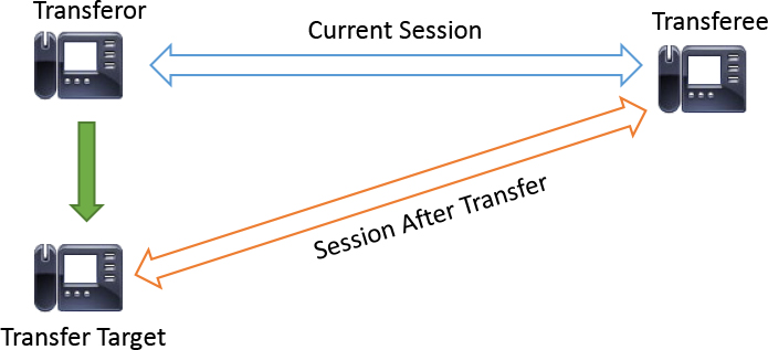
Figure 9-12 Transferor, Transferee, and Transfer Target Illustrated
REFER Transfer
The SIP REFER method was defined and standardized in RFC 3515 to provide a framework for call transfers in SIP networks. Over the years, several modifications have been made to the implementation of the SIP REFER method to fit a variety of application usages. This section provides an overview of the basic implementation of the SIP REFER method outlined in RFC 3515.
A user agent (transferor) attempting to transfer a call (to the transfer target) does so by sending a SIP REFER request to the transferee. Included in the SIP REFER request is information on how the transferee can reach the transfer target; this information is encapsulated in the Refer-To header field (see Example 9-13). For a REFER request to be sent, there needs to be an established, active communication session between the transferor and transferee. The REFER request is sent on the same SIP dialog as the established communication session to ensure that the request is delivered to the intended recipient, can be correctly correlated by the transferee to the existing communication session, and is from an authorized source.
Example 9-13 Sample REFER and the Refer-To Header
REFER sip:[email protected] SIP/2.0
Via: SIP/2.0/UDP agenta.atlanta.example.com;branch=z9hG4bK2293940223
To: <sip:[email protected]>
From: <sip:[email protected]>;tag=193402342
Call-ID: [email protected]
CSeq: 93809823 REFER
Max-Forwards: 70
Refer-To: sip:[email protected]
Contact: sip:[email protected]
Content-Length: 0
The SIP REFER request creates an implicit subscription between the transferor and transferee. This subscription is then used by the transferee to notify the transferor of the status of processing the REFER request. The messages sent in this implicit subscription are detailed in Figure 9-13.
![]()

Figure 9-13 High-Level REFER Overview
The SIP REFER method for call transfer proceeds as follows:
Step 1. A communication session is established between Party A and Party B. At some time during the call, Party A decides that the call needs to be transferred to another party, Party C.
Step 2. A SIP REFER request is sent from Party A to Party B, such that the request carries a Refer-To header. The Refer-To header field encapsulates the SIP URI of Party C.
Step 3. On receiving the SIP REFER request, Party B parses the request to ensure correct formatting. If the request is incorrectly formatted, the request is rejected, with an appropriate error code. For example, if the REFER request carries zero or more than one Refer-To header field, it is rejected with a 400 Bad Request response.
Step 4. If the request is correctly formatted, Party B sends a 202 Accepted response to Party A. This response also results in the establishment of an implicit SIP subscription between Party A and Party B, and the aim of the subscription is for Party B to notify Party A of the status of processing the REFER request.
Step 5. Immediately after sending a 202 Accepted response, Party B sends a SIP NOTIFY request to Party A. In parallel, it attempts to create a communication session with Party C, using the URI specified in the Refer-To header field of the REFER request.
Step 6. The results of the attempt to establish a communication session with Party C are encapsulated in subsequent NOTIFY messages sent from Party B to Party A. If Party B succeeds in establishing a communication session with Party C, it sends a SIP NOTIFY with the SIP response status line SIP/2.0 200 OK. If the attempt is unsuccessful, it sends a SIP NOTIFY with a SIP response status line or SIP/2.0 603 Declined.
Note that the implicit subscription created by the REFER request can either be explicitly or implicitly terminated by the transferor (Party A) at any time. Termination of the subscription should not negatively impact the outcome of REFER processing by the transferee (Party B). SIP NOTIFY messages sent by the transferee to the transferor indicate the outcome of request processing at the transferee. Every NOTIFY message must contain a message body of type message/sipfrag and must include an Event header field with the tag value refer. Example 9-14 displays a SIP NOTIFY message with a message body containing SIP/2.0 100 Trying to let the transferor know the request is being processed.
Example 9-14 Sample SIP NOTIFY Message with a 100 Trying sipfrag Body
NOTIFY sip:[email protected] SIP/2.0
Via: SIP/2.0/UDP agentb.atlanta.example.com;branch=z9hG4bK9922ef992-25
To: <sip:[email protected]>;tag=193402342
From: <sip:[email protected]>;tag=4992881234
Call-ID: [email protected]
CSeq: 1993402 NOTIFY
Max-Forwards: 70
Event: refer
Subscription-State: active;expires=(depends on Refer-To URI)
Contact: sip:[email protected]
Content-Type: message/sipfrag;version=2.0
Content-Length: 20
SIP/2.0 100 Trying
When the transfer is answered, the device handling the REFER sends one last NOTIFY message, specifying 200 OK. This final NOTIFY message contains the SIP header Subscription-State: terminated;reason=noresource to indicate that this is the final NOTIFY message, and the REFER process is complete. Example 9-15 displays a SIP NOTIFY message with a message body containing SIP/2.0 200 OK, indicating to the transferor that the REFER has been processed completely, and a session with the transfer target has been established.
Example 9-15 Sample NOTIFY Message with a 200 OK sipfrag Body
NOTIFY sip:[email protected] SIP/2.0
Via: SIP/2.0/UDP agentb.atlanta.example.com;branch=z9hG4bK9323394234
To: <sip:[email protected]>;tag=193402342
From: <sip:[email protected]>;tag=4992881234
Call-ID: [email protected]
CSeq: 1993403 NOTIFY
Max-Forwards: 70
Event: refer
Subscription-State: terminated;reason=noresource
Contact: sip:[email protected]
Content-Type: message/sipfrag;version=2.0
Content-Length: 16
SIP/2.0 200 OK
As mentioned earlier in this section, a number of enhancements to the REFER method are defined in RFC 3515. RFC 3892 defined a new header, Referred-By, for use in REFER-based transfers scenarios. The user agent originating a REFER request may include a single Referred-By header, which has the following format:
Referred-By: <sip-uri>
A user agent processing a REFER containing a Referred-By header may include the Referred-By header within the SIP INVITE request sent to the refer target indicated in the Refer-To header. The use of the Referred-By header allows the refer target to parse the SIP URI provided and authenticate the call transfer by using local logic. For example, say that there is an established session between Alice and Bob. Bob attempts to transfer Alice to a refer target, Josh. The Referred-By header would state that Bob is the one referring Alice to Josh. Josh may have in place logic that rejects a call transfer if Bob is the referring party, and this is communicated to Josh by the content of the Referred-By header.
The use of a Referred-By header is entirely optional and not required for a successful REFER-based transfer to complete. However, a device may require that a Referred-By header be present to satisfy local logic and permit session establishment. In this scenario, a 429 Provide Referrer Identity may be sent in response to a REFER/INVITE that does not contain a Referred-By header.
Tip
This chapter does not discuss out-of-dialog (OOD) REFER messages.
Often the transferor, transferee, and transfer target are on different networks. In such scenarios, there may be many different devices, such as a third-party call agent and a CUBE, involved in the session. In such a scenario, the REFER request is sent from the transferor to other signaling devices involved in the session. These devices can take one of two actions with a received REFER request:
• The device can act on behalf of the transferee and attempt to establish a session with the transfer target defined in the Refer-To header of the REFER request.
• The device may pass the REFER request from one call leg to the peer call leg without acting on the REFER request.
The first method of REFER handling, detailed previously, is often referred to as REFER consume. In this scenario, CUBE consumes the REFER request, as shown in Figure 9-14, and takes action on the provided URI in the Refer-To header. If the Refer-To header contains a SIP URI, the CUBE extends an INVITE between itself and the user agent identified in the Refer-To header in an attempt to establish a session. This is the most common implementation of SIP REFER handling on an SBC.
![]()

Figure 9-14 REFER Consumption on CUBE
With the second method, CUBE performs a passthrough of the REFER so that a downstream device can take further action on the REFER request. This method can be used to potentially remove CUBE from further signaling after the transfer is complete. This method is often used when transferring an off-net PSTN party to another off-net PSTN party. Both the transfer target and the transferee are not on the network that CUBE is responsible for, so the SBC may be dropped from the signaling. Figure 9-15 shows this method.
![]()
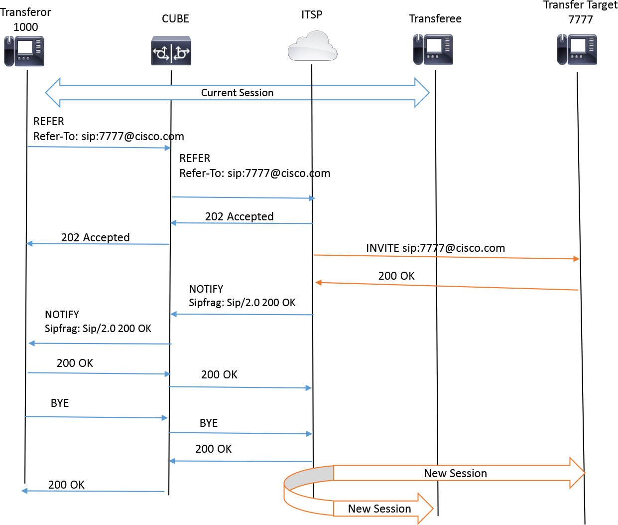
Figure 9-15 REFER Passthrough on an SBC
CUBE can be configured to either consume or pass across a received REFER message. Using the configuration example in Example 9-16, when CUBE receives a REFER message, it does not process the REFER message but instead creates an egress REFER message with the same information and sends it to the peer hop. When the REFER transfer is complete in this scenario, CUBE is no longer involved in the call. Most ITSPs do not support REFER-based transfers, so REFER consume is often used.
Example 9-16 CUBE REFER Passthrough Configuration
voice service voip
 supplementary-service sip refer
 no supplementary-service media-renegotiate
sip
referto-passing
Example 9-17 shows how to configure CUBE to consume and completely process the REFER request. When this method is used, CUBE parses the user portion of the request URI in the Refer-To header. This is used as the key for performing a dial peer lookup. When the dial peer matching logic is satisfied, an outbound INVITE is sent to the session target defined on the dial peer. When the REFER is complete, CUBE is still involved in the signaling and session. The transferor who sent the REFER is removed, and the session now involves the transferee, CUBE, and the transfer target. The supplementary-service command for media renegotiation is included to allow CUBE to renegotiate end-to-end media capabilities when consuming the REFER and establishing the new session call leg.
Example 9-17 CUBE REFER Consumption Configuration
voice service voip
 no supplementary-service sip refer
 supplementary-service media-renegotiate
sip
no referto-passing
Cisco Unified Communications Manager Express (Unified CME) and Unified CM also leverage SIP REFER for transfer purposes. Unified CM’s use of REFER is covered in the next section, and the Unified CME process is covered in Chapter 10, “Unified CME and SRST.” Note that if Unified CM is engaged in a call where the inbound device and outbound device are both SIP trunks, a REFER message received on one SIP trunk can be passed through Unified CM and sent on the other SIP trunk with the aid of the “refer-passthrough” SIP normalization script. Unified CM never sends a REFER outbound on a SIP trunk for calls being transferred by an IP phone. In this scenario, an INVITE transfer is used. The next section discusses how Unified CM performs this type of transfer involving IP phones.
INVITE Transfer
Another method of call transfer, which is primarily used by SIP IP phones, Unified CM, and Unified CME, is achieved by using SIP INVITE messages. During a call transfer that utilizes a SIP INVITE to create a new call and call leg, the original media stream may be temporarily suspended while a new INVITE message is being processed. When the call transfer is complete, the original call and the call established with the new INIVTE message are bridged together; the media stream is subsequently reestablished between the transferee and the transfer target.
Note
The upcoming examples feature CUBE sending an inbound call to Unified CM, which routes the call to an IP phone. The IP phone then transfers the call to another endpoint registered to the same Unified CM cluster. The peer call leg of CUBE has been omitted to simplify the diagrams.
To initiate the hold and new INVITE transfer process, the transferor presses a button or softkey, which places the transferee on hold. While the transferee is on hold, the transferor can initiate a call transfer by dialing the number of a transfer target. During this process, a minimum of four different call legs are created on Unified CM between the different endpoints. These call legs will be discussed further later on, but for now you just need to know these basics:
• Call Leg 1: This is the original ingress unified CM call leg. This was the call leg starting from the endpoint that initiated the call. Call Leg 1 could easily be another SIP IP phone, but for upcoming examples this call leg is from CUBE and assumes the role of the transferee.
• Call Leg 2: This is the original egress unified CM call leg. This is the call leg Unified CM used to connect the call to the IP phone endpoint. For the upcoming examples, this device takes the role of the transferor.
• Call Leg 3: This is the new call leg created by the transferor to reach the transfer target. This is sent to Unified CM to facilitate interworking.
• Call Leg 4: This is the new egress unified CM call leg created to connect with the transfer target.
When the transfer is completed in the upcoming examples, Call Legs 1 (transferee) and 4 (transfer target) are connected, and Call Legs 2 and 3 (transferor) are removed from the session. Note that either Call Leg 1 or Call Leg 2 can assume the role of a transferor, making the other the transferee. After dialing the transfer target number, the transferor can complete the transfer in one of few ways.
The first transfer method is termed an unattended transfer, or blind transfer, which means a call is directed to the transfer target, and when the transfer target answers, audio is connected between the transferee and the transfer target. The transferor is dropped from the session before the transfer target answers. Figure 9-16 provides a high-level overview of the events that occur in a blind transfer with Unified CM, CUBE, and two IP phones. This figure serves as the basis for discussing blind transfer in upcoming paragraphs.
![]()

Figure 9-16 High-Level Overview of Blind Transfer with Unified CM, CUBE, and Two IP Phones
The blind transfer in Figure 9-16 occurs as follows:
![]()
Step 1. CUBE sends a call to Unified CM; this is Call Leg 1.
Step 2. Unified CM creates Call Leg 2 and sends the call to the IP phone, which assumes the role of transferor.
Step 3. The audio is now connected with bidirectional (two-way) media.
Step 4. The transferor places the original call with the transferee on hold by pressing the Transfer softkey or button a single time. This triggers normal hold/resume signaling (as discussed earlier in this chapter) while the user performs the rest of the transfer sequence.
Step 5. The Unified CM endpoint creates a new call (Call Leg 3) and sends a new INVITE message to Unified CM with the transfer target’s number after the user dials the number.
Step 6. Unified CM works to route the call to the transfer target and creates Call Leg 4.
Step 7. At any point, usually once ringback is heard to confirm that the transfer target is being called, the transferor may press the Transfer softkey or button again to confirm the transfer. If the Unified CM service parameter setting Transfer On-Hook Enabled is set to True, the IP phone may also simply hang up the call to complete the transfer. The Unified CM endpoint sends a REFER (on Call Leg 2) with a Refer-To SIP header that contains a tag with the call-id, the to header tag, and the from header tag that references the call ringing the transfer target.
Step 8. Unified CM works to interwork the transferee (Call Leg 1) and transfer target (Call Leg 4) based on this REFER message. The transferor call legs (Call Legs 2 and 3) are removed from the session.
Step 9. Because the transfer has been completed by the IP phone, ringback is played to the transferee to signal that the remote party is being called and proceeding normally. The ringback continues until the transfer target answers the call. Because the call is already connected, an 18x message is not sent; instead, a media resource such as the Unified CM annunciator is required to play ringback to the transferee.
Step 10. When the call is answered by the transfer target, Unified CM de-allocates the annunciator and renegotiates media with the transferee and transfer target.
Figures 9-17, 9-18, and 9-19 provide a more granular view of these steps. The main SIP signaling exchanges have been included for all four call legs for a blind transfer, although some signaling—such as the SIP SUBSCRIBE, SIP KPML, and SIP 1xx messages—has been omitted for brevity.
Figure 9-17 illustrates the initial SIP three-way handshake to establish the call between the calling party and the called party and then the hold signaling observed when the Transfer key is pressed for the first time. Note that the hold signaling occurs twice: first to remove the media and then to establish MOH. (The first removal of media has been omitted from this figure for brevity.)
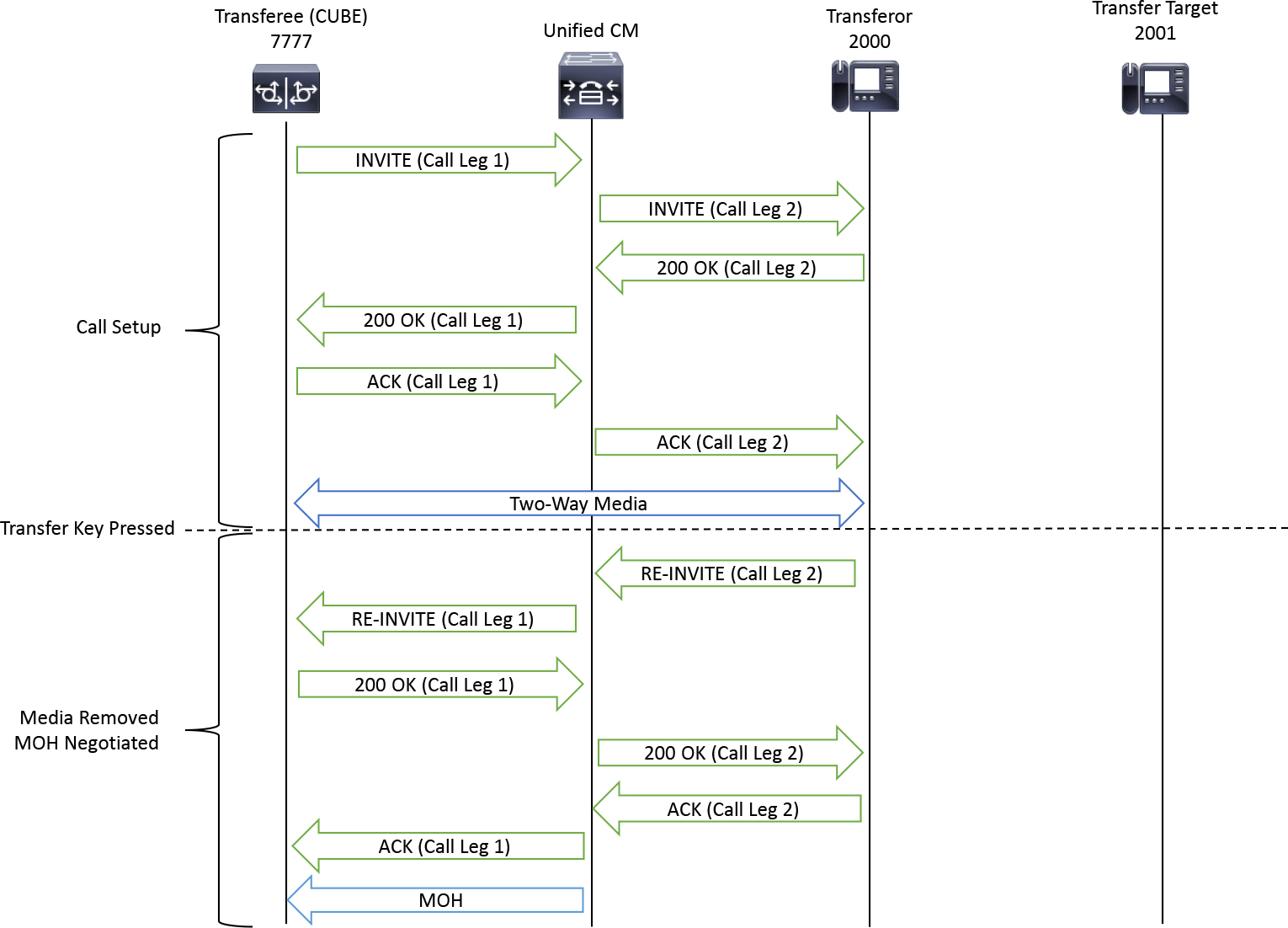
Figure 9-17 The Initial Call Signaling and Hold
Figure 9-18 starts with the initial call on hold, and a new call leg (Call Leg 3) is created by the transferor to call the transfer party. This new call is sent to Unified CM, which performs digit analysis and finds a callable endpoint. Unified CM attempts to establish a new session with the transfer target specified by the transferor. This results in the creation of Call Leg 4. Here an INVITE message is sent to the transfer target, and a 180 Ringing message is received by Unified CM. This 180 Ringing message is relayed to the transferor. The transferor now hears ringback and knows the transfer target has been called successfully. At this point, the Transfer key is pressed again to start the blind/unattended transfer. A REFER message is sent to Unified CM on Call Leg 2, and it contains a Refer-To header with a Replaces tag that includes the call-id, a to header tag, and the from header tag of Call Leg 3. Unified CM then removes MOH on Call Leg 1 to replace the MOH with ringback streamed from a local annunciator. The two call legs involving the transferee are disconnected with a SIP BYE. At this point, the transferee is hearing ringback while the transfer target is ringing.
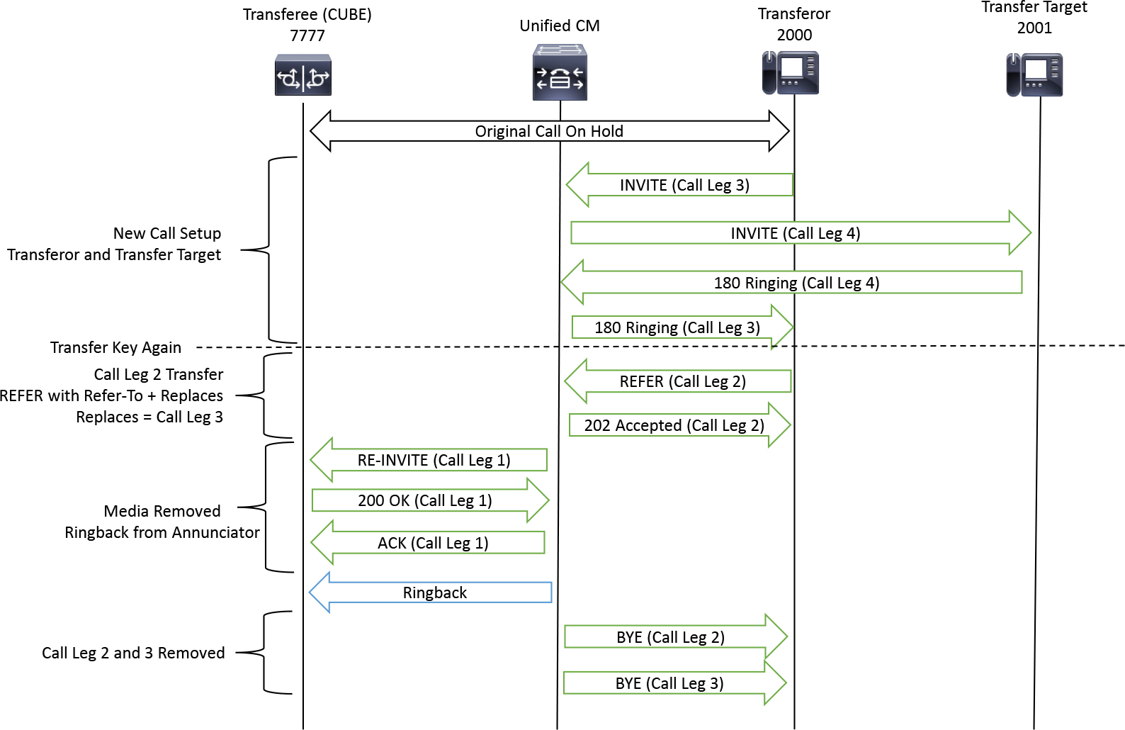
Figure 9-18 Unified CM Facilitating the Transfer Between the Transferee, Transferor, and Transfer Target
Example 9-18 The REFER on Call Leg 2, Which Instructs Unified CM to Replace the Call with the Call from the Session Established on Call Leg 3.
Call Leg 3 180 Ringing
SIP/2.0 180 Ringing
Via: SIP/2.0/TCP 14.50.214.107:49335;branch=z9hG4bK560d6e41
From: “2001” <sip:[email protected]>;tag=d0ec35ffeafe386b008239c9-6f35b7fb
To: <sip:[email protected]>;tag=45272~594cd2d2-a0cb-41cd-93ca-ed8ff9be0241-18391233
Date: Thu, 10 Oct 2019 22:54:25 GMT
Call-ID: [email protected]

Call Leg 2 REFER
REFER sip:[email protected]:5060;transport=tcp SIP/2.0
Via: SIP/2.0/TCP 14.50.214.107:49335;branch=z9hG4bK4cb47f68
From: <sip:[email protected]>;tag=d0ec35ffeafe386a7536e6b5-1004520c
To: <sip:[email protected]>;tag=45268~594cd2d2-a0cb-41cd-93ca-ed8ff9be0241-18391231
Call-ID: [email protected]
Max-Forwards: 70
Session-ID: 27ee888100105000a000d0ec35ffeafe;remote=93b0261bb9aa565d9a659953acc5c518
Date: Thu, 10 Oct 2019 22:54:20 GMT
CSeq: 103 REFER
User-Agent: Cisco-CP8865/12.1.1
Contact: <sip:[email protected]:49335;transport=tcp>;+u.sip!devicename.ccm.cisco.com="SEPD0EC35FFEAFE";video
Refer-To: <sip:[email protected]?Replaces=d0ec35ff-eafe0008-474553bb-079c2d73%4014.50.214.107%3Bto-tag%3D45272~594cd2d2-a0cb-41cd-93ca-ed8ff9be0241-18391233%3Bfrom-tag%3Dd0ec35ffeafe386b008239c9-6f35b7fb>
Referred-By: <sip:[email protected]>
Content-Length: 0
Figure 9-19 starts where Figure 9-18 left off: The transferee is being called, and the transfer target is actively ringing. Unified CM sends an UPDATE message to each caller that contains caller ID information of the new parties. (The UPDATE message is discussed in upcoming sections.) Once the transfer target answers the call, Unified CM removes the annunciator and renegotiates media with the transferee. At this point, the call is connected with media flowing between the transferee and transfer target.

Figure 9-19 The Caller ID Updates and Media Connection After the Transfer Target Answers
Another transfer method that is often seen with Unified CM endpoints is the consult transfer, or attended transfer. In this type of transfer, the call is sent to the transfer target, and when the transfer target answers, audio is connected between the transferor and the transfer target. The transferee remains on hold while the transferor and transfer target are engaged in conversation. To complete the transfer, the transferee may press the Transfer button again, and the transferor is then removed from the session, and the transferee and transfer target audio session is established. Figure 9-20 provides a high-level overview of the events that occur in a consult transfer with Unified CM, CUBE, and two IP phones. This figure serves as the basis for discussing consult transfer in upcoming paragraphs.
![]()
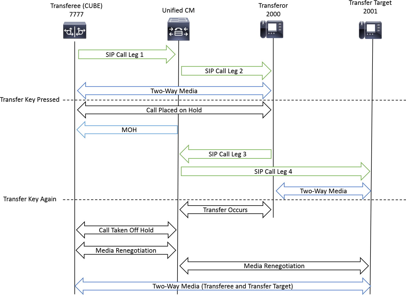
Figure 9-20 High-Level Overview of Consult Transfer with Unified CM, CUBE, and Two IP Phones
The consult transfer in Figure 9-20 occurs as follows:
![]()
Step 1. CUBE sends a call to Unified CM. This is Call Leg 1.
Step 2. Unified CM creates a Call Leg 2 and sends the call to the IP phone, which assumes the role of transferor.
Step 3. The audio is now connected with bidirectional (two-way) media.
Step 4. The transferor places the original call with the transferee on hold by using a Transfer softkey or button on the endpoint. This call uses the normal hold/resume signaling discussed earlier in this chapter.
Step 5. The Unified CM endpoint creates a new call (Call Leg 3) and sends a new INVITE message to Unified CM with the transfer target’s number after the user dials the number.
Step 6. Unified CM works to route the call to the transfer target and creates Call Leg 4.
Step 7. Up until this point, the transfer process has been exactly the same between blind/attended and consult/unattended transfers. The differences occurs when the transferor waits for the transfer target to answer the call, at which point an audio session is established between the transferor and the transfer target. The transferee remains on hold. At any point, the transferor can press the Transfer softkey or button again to confirm the transfer.
Step 8. The Unified CM endpoint sends a REFER (on Call Leg 2) with a Refer-To SIP header that contains a replaces tag referencing the call-id, the to header tag, and the from header tag that references the call ringing the transfer target.
Step 9. Unified CM works to interwork the transferee (Call Leg 1) and transfer target (Call Leg 4) based on this REFER. The transferor call legs (Call Legs 2 and 3) are removed from the session.
Step 10. No ringback is played to the transferee because the media renegotiation between the transferee and transfer target begins immediately. The MOH resource is de-allocated, and an audio stream is established between the transferee and the transfer target.
Figures 9-21, 9-22, and 9-23 provide a more granular view of these steps discussed. The main SIP signaling exchanges have been included for all four call legs for a consult transfer, although some signaling—such as the SIP SUBSCRIBE, SIP KPML, and SIP 1xx messages—has been omitted for brevity.
Figure 9-21 starts from the point of Figure 9-17 that details the initial call setup and hold. A SIP three-way handshake occurs to establish the call between the calling party and the called party and then hold signaling occurs when the Transfer key is pressed for the first time. Note that the hold signaling occurs twice: first to remove the media and then to establish MOH. (The first removal of media has been omitted for brevity.)
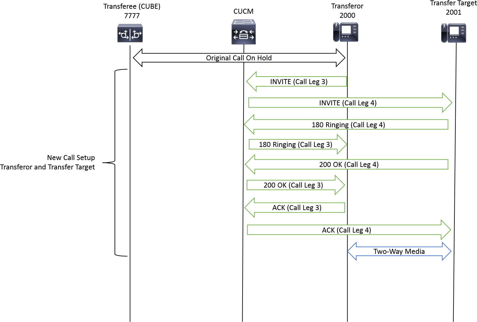
Figure 9-21 Unified CM Facilitating the Transfer Between the Transferee, Transferor, and Transfer Target with the Transferor and Transfer Target Connecting Audio
Figure 9-21 starts with the initial call on hold. A new call leg (Call Leg 3) is created by the transferor to call the transfer target. This is sent to Unified CM, which performs digit analysis and finds a callable endpoint. Unified CM attempts to establish a new session with the transfer target specified by the transferor. This results in the creation of Call Leg 4. Here an INVITE message is sent to the transfer target, and a 180 Ringing message is received by Unified CM. This 180 Ringing message is relayed to the transferor. The transferor now hears ringback and knows the transfer target has been called successfully.
The transferor may elect to wait until the transfer target answers rather than press the Transfer key again to confirm the transfer and start the blind/unattended transfer process. When the transfer target answers, the SIP three-way handshake is complete, and media is negotiated between the transferor and the transfer target.
Figure 9-22 starts with the original call on hold, while the transferor and transfer target are engaged in a session. When the transferor is ready to confirm the transfer, the softkey may be pressed again to confirm the transfer. A REFER message is sent to unified CM on Call Leg 2; it contains a Refer-To header with a Replaces tag that includes the call-id, the to header tag, and the from header tag of Call Leg 3. Functionally, this REFER message is the same in both blind and consult transfers. (Examine the REFER message in Example 9-18 for more information.) Unified CM then removes MOH on Call Leg 1 in order to start media renegotiation. The media is also removed on Call Leg 4 to start media renegotiation. The two call legs involving the transferee are disconnected with a SIP BYE message. Finally, Unified CM updates the caller ID information for both the transferee and the transfer target.
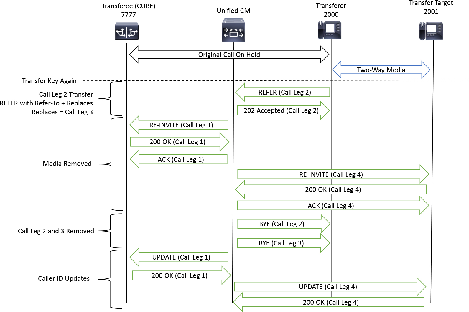
Figure 9-22 Unified CM Facilitating the REFER to Remove the Transferor and Connect the Transferee and Transfer Target
Figure 9-23 wraps up the consult transfer process by detailing the media renegotiation, which simply involves a SIP three-way handshake on Call Leg 1 and Call Leg 4 to determine media capabilities and connect media between the transferee and the transfer target.

Figure 9-23 Media Renegotiation Between the Transferee and Transfer Target
For these two transfer methods, Unified CM is responsible for inviting the transfer target to the session as well as for the hold and resume the transferee experiences and also for the renegotiation of media for the transfer target, transferee, and transferor. In some scenarios, the transfer target may be a device on the PSTN, which means that CUBE may be both the transferee and the transfer target from Unified CM’s perspective. From CUBE’s perspective, an INVITE-based transfer makes use of two different call dialogs. The first SIP dialog is the original call between the transferor and the transferee. The second is a new SIP dialog between the call agent, on behalf of the transferor, and the transfer target. While CUBE can interwork REFER similarly to Unified CM, Unified CM never passes through a SIP REFER message received from a phone to a SIP trunk, so Unified CM and CUBE remain involved while the transferor is removed from the session.
REFER Versus INVITE Transfers
When comparing REFER and INVITE transfer methods from CUBE’s perspective, you can quickly see the benefits and drawbacks. With REFER-based transfers, CUBE can be eliminated from the signaling–and even from the media path, as noted in the previous sections. In contrast, with INVITE-based transfers, Unified CM and CUBE are often left in the signaling path even when the transferee and transfer target are not on the enterprise LAN. At this writing, Unified CM supports only INVITE as the transfer method for SIP trunks, and Unified CM never sends a REFER message to CUBE. CUBE will continue to support either type of transfer method because other vendors and other Cisco applications, such as contact center call progress analysis (CPA) features, support the REFER-based transfer with CUBE.
For media interworking, CUBE can be configured with the command media anti-trombone, as shown in Example 9-19, to perform best-effort media loop detection. With this command in place, CUBE looks for matching SDP in the two SIP dialogs. If similar media characteristics such as IP and port are found, media anti-trombone can attempt to advertise the transferee and transfer target’s media information to either, which eliminates CUBE from the media path. Figure 9-24 illustrates a call transfer with and without media anti-trombone.
Example 9-19 Enabling the Media Anti-Trombone Feature on CUBE
!
voice service voip
 media anti-trombone
!

Figure 9-24 A Visual Comparison of Operation With and Without the Anti-Trombone Feature
UPDATE Interworking
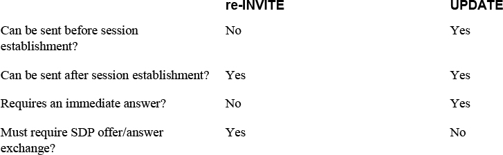
The SIP UPDATE method, defined in RFC 3311, provides a way for a SIP user agent to modify session characteristics before the call is answered. The SIP UPDATE method is similar to the SIP re-INVITE method, but the main difference is that the SIP UPDATE can be used to modify session characteristics before a session is established, and a SIP re-INVITE cannot do this. Table 9-3 shows the differences between the two method types.
Table 9-3 Comparison of re-INVITE and UPDATE Request Methods
A device advertises its capability to support the SIP UPDATE method by specifying this method in the Allow header (see Example 9-20). This can be in a request or in a response. In addition, an UPDATE may or may not contain SDP. UPDATE messages without SDP usually modify session characteristics such as the caller ID and session timers, whereas UPDATE messages with SDP directly modify the session's media attributes.
Example 9-20 An Allow Header with the UPDATE Method Specified
INVITE sip:[email protected]:5060 SIP/2.0
Via: SIP/2.0/TCP 172.18.110.48:5060;branch=z9hG4bK59c13d0833e
From: <sip:[email protected]>;tag=30489~1992ce86-77ac-43a7-91b7-90778966a9f5-30207788
To: <sip:[email protected]>
Call-ID: [email protected]
Supported: timer,resource-priority,replaces
Min-SE:  1800
Allow: INVITE, OPTIONS, INFO, BYE, CANCEL, ACK, PRACK, UPDATE, REFER, SUBSCRIBE, NOTIFY
CSeq: 101 INVITE
Expires: 180
Session-Expires:  1800
Contact: <sip:[email protected]:5060;transport=tcp>
Max-Forwards: 70
Content-Length: 0
SIP/2.0 183 Session Progress
Via: SIP/2.0/TCP 172.18.110.48:5060;branch=z9hG4bK59c13d0833e
From: <sip:[email protected]>;tag=30489~1992ce86-77ac-43a7-91b7-90778966a9f5-30207788
To: <sip:[email protected]>;tag=66EF7A-1E33
Call-ID: [email protected]
CSeq: 101 INVITE
Allow: INVITE, OPTIONS, BYE, CANCEL, ACK, PRACK, UPDATE, REFER, SUBSCRIBE, NOTIFY, INFO, REGISTER
Contact: <sip:[email protected]:5060;transport=tcp>
Content-Length: 0
A SIP UPDATE request may be sent by any participant in a session. However, there are specific guidelines related to when it is and is not appropriate to send a SIP UPDATE. These are broken down into three key scenarios:
![]()
• If the original offer does contain a session media description (early offer) and this offer is answered reliably by a PRACK exchange (as described earlier in this chapter), an UPDATE message may be sent for session description modification. Figure 9-25 illustrates an early offer call in which a UAS has sent a 183 with SDP. The PRACK is exchanged, and the offer/answer has been completed reliably. However, the UAC wants to change the aspects of the media session. Because the call is not yet answered by the UAS with a final response, the UAS sends an UPDATE message with SDP. The UAS responds with a 200 OK with SDP. This can continue as many times as needed until a final response to the INVITE message is processed. If the offer is not answered reliably with PRACK, only an UPDATE message without SDP can be processed for this session.
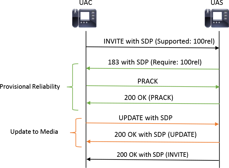
Figure 9-25 PRACK and UPDATE Between a UAC and a UAS
• If the original offer does not contain any offer (delayed offer), an UPDATE message for session media modification cannot be processed unless an answer/offer PRACK exchange occurs. In this scenario, the provisional response (such as a 183 with SDP) would contain an offer, and the PRACK with SDP would contain the answer. If the aforementioned offer/answer has yet to be finalized, only an UPDATE message without SDP can be processed at this point in the session.
• UPDATE messages for session media modification may be used after the initial INVITE transaction has been completed, as long as there are no outstanding offers (re-INVITE or UPDATE) awaiting answers. If there is an outstanding transaction awaiting an answer to an offer and an UPDATE is received, this solicits a 491 response. Similarly, if there is an outstanding transaction in which the device receiving the UPDATE is in the process of generating an answer, the response must be a 5xx-level response with a Retry-After header. This is the same response code and behavior observed if a device attempts to send an UPDATE message before a previous UPDATE message of any kind has been answered with a 200 OK.
One problem that arises in the scenario of updating a session description before a call is connected has to do with the asymmetrical nature of PRACK. Because PRACK is a per–call leg mechanism, from the perspective of CUBE, a reliable provisional response might be exchanged on one call leg and not on the other. This scenario is depicted in Figure 9-26. In this scenario, it is valid for the device on Call Leg A to send an UPDATE message with SDP to the SBC. The SBC would either need to respond to the UPDATE message on behalf of Call Leg B or return a 491 Request Pending message back to Call Leg A because it is unable to pass the UPDATE message with SDP to Call Leg B.

Figure 9-26 Asymmetric PRACK, UPDDATE, and 491 Responses
For such scenarios, SBCs can be configured to locally consume SIP UPDATE messages without passing the request to the peer call leg. From the perspective of CUBE, local consumption of SIP UPDATE messages can be achieved be configuring early-media update block, as demonstrated in Example 9-21.
Example 9-21 Configuring a CUBE Early Media Update Block
voice service voip
 sip
early-media update block
As mentioned earlier in this chapter, UPDATE messages are commonly used to modify caller ID when a remote device transfers a call or when additional parties are added to the call. This can be done at any time during a session and does not require any prerequisite signaling exchanges, such as PRACK. Most SBCs forward these types of UPDATE messages on the peer call leg by default. It is common to observe this method of UPDATE message in conjunction with the call transfer events discussed earlier in this chapter. When a device transfers from one party to another, often the caller ID of the new participant is sent in an UPDATE message to the other participants in the session. By default, CUBE passes through mid-call UPDATE messages for caller ID changes. The passing of these messages may lead to additional SIP traffic being sent to the service provider, which also increases bandwidth on the network and could even lead to race conditions when an UPDATE message is not expected. Thus, the default behavior of passing caller ID updates can be changed by removing the default command, as shown in Example 9-22.
Example 9-22 Disabling CUBE Update Caller ID
voice service voip
 sip
no update-callerid
Session Refresh
It is quite common for a communication session established over SIP to span several intermediary devices, such as call agents, SIP proxies, and SBCs. In such scenarios, it is vital that requests and corresponding responses be transmitted reliably and in a timely manner end to end to ensure that the state of the communication session is synchronized across all devices in the call path. Consider a situation in which a communication session is established across the topology depicted in Figure 9-27.
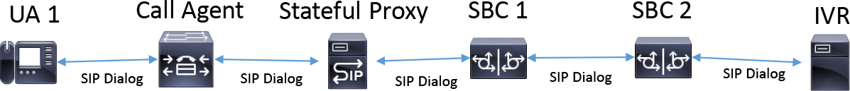
Figure 9-27 Topology with UA, Call Agent, Stateful Proxy, SBCs, and an IVR Device
The IVR device is capable of only triggered disconnects. That is, it can terminate a communication session only when it receives SIP BYE requests and not of its own accord. In Figure 9-28, which uses the topology shown in Figure 8-27, if the caller decides to end the communication session, it transmits a SIP BYE message or an equivalent indication. This indication is transmitted across all devices along the call path such that it is received at the IVR device. The IVR device then acknowledges this request, leading to the termination of the communication session.

Figure 9-28 A BYE Sent to All Participants in the Session
Figure 9-29 illustrates a scenario in which the indication to disconnect the communication session (SIP BYE) is lost in transit or is not processed properly on one of the downstream devices due to a transient condition, and as a result, the state of the session is not synchronized end to end. This leads devices along the call path that haven't received the indication for call disconnect to believe that the communication session is still active. This situation would also needlessly result in resources being held up on such devices. To overcome such situations, the IETF standardized the constructs of RFC 4028 as a mechanism to determine session freshness.
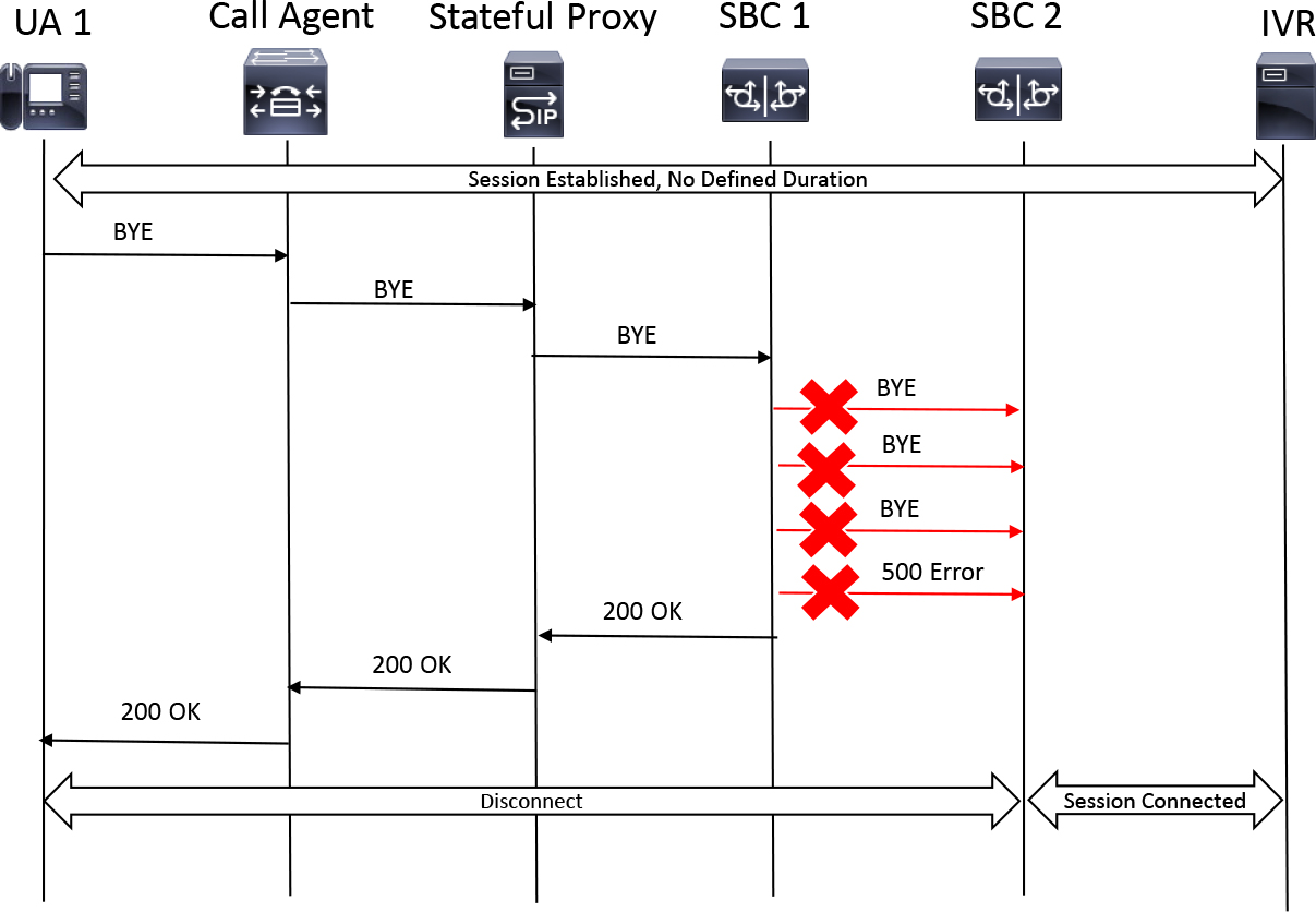
Figure 9-29 A Transient Condition in Which BYE Is Not Received by All Session Participants
RFC 4028 defines many different terms. For example, a session interval is conveyed in the Session-Expires SIP header. This header conveys the maximum time a session is considered active or fresh. After this timer expires, the session is timed out, and all devices that have agreed on the session interval disconnect the session. This disconnection is called a session expiration. The minimum timer is carried in the Min-SE SIP header and is used to convey the lowest possible value for the session interval. To modify or extend a previously agreed upon session interval, a session refresh must occur; it is carried out by the predetermined refresher. Figure 9-30 illustrates a sample of a session interval being negotiated between a UAC and a UAS. Next, we break down this signaling exchange, using Figure 9-30 as a starting point.
![]()

Figure 9-30 Session Timer Negotiation Between a UAC and a UAS
If a UAC wants to engage in a new session with a session interval, it must first include the timer extension in the Supported SIP header. A Session-Expires header may also be included in the initial INVITE request, indicating a proposed maximum session interval. It is important to note that the Session-Expires header sent by the UAC is an offer and a proposed timer. Thus, this value may not reflect the final timer value negotiated for the session. The timer extension may be included in the Require header to indicate that the UAC is requesting that the UAS also support a session timer to participate in the session. If the UAC wants to convey a minimum session interval, the UAC may include the Min-SE header. Finally, if the UAC wants, it may indicate that it would like to play the role of refresher for this session by adding the tag ;refresher=uac to the Session-Expires header. If the UAC would like to leave this decision up to the UAS, it may omit this tag from the Session-Expires header. Example 9-23 shows a sample INVITE request for a new session requesting a session interval.
Example 9-23 Sample INVITE with Session Interval Information
INVITE sip:[email protected]:5060 SIP/2.0
Via: SIP/2.0/TCP 172.18.110.48:5060;branch=z9hG4bK3a34b28097e
From: <sip:[email protected]>;tag=22968~1992ce86-77ac-43a7-91b7-90778966a9f5-30207629
To: <sip:[email protected]>
Call-ID: [email protected]
Supported: 100rel,timer,resource-priority,replaces
Min-SE: 900
Allow: INVITE, OPTIONS, INFO, BYE, CANCEL, ACK, PRACK, UPDATE, REFER, SUBSCRIBE, NOTIFY
CSeq: 101 INVITE
Expires: 180
Session-Expires: 1800;refresher=uac
Max-Forwards: 69
The UAS or midstream proxy receiving a request with a proposed session interval may perform one of many actions, including the following:
• If the device handling a request with a Require header contains the timer extension but does not support session timers or the timer extension, it may send a 420 Bad Extension response.
• If the device handling a request that contains only a Supported header with the timer extension and no Session-Expires header, it may include a Session-Expires header with its own proposed session value in the 200 OK response to the INVITE message. The UAC may then answer this session interval offer in the ACK.
• If the device handling a request contains a Supported header with the timer extension and a Session-Expires header with a value, it may generate a 200 OK response without a Session-Expires header (as long as there is not a Require timer header present). By doing this, the UAS indicates that there is no defined session interval for the session.
• Alternatively, if the device handling a request contains a Supported header with the timer extension and a Session-Expires header with a value, the device may include a Session-Expires with a value equal to or lower than the value contained in the Session-Expires header sent by the UAC. This value cannot be lower than the Min-SE header value indicated by the UAC if the header was present.
• Finally, as shown in Figure 9-31, if the value of the Session-Expires header is lower than the desired minimum session expiration for the device, it may send a 422 Session Interval Too Small response. The 422 response must contain a Min-SE header specifying the minimum timer allowed by the server rejecting the message. The UAC may attempt to increase the timer and try the request again or try another UAS, using local logic.
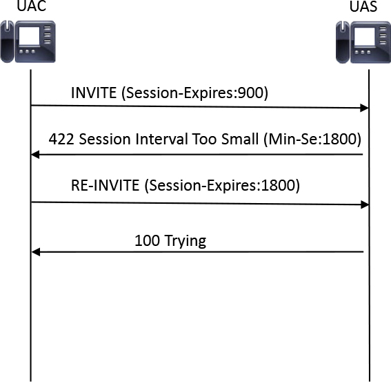
Figure 9-31 422 Response to a Request Containing a Session Timer That Is Too Small
The minimum for any session interval is 90 seconds. In addition, when no Min-SE header is present, the assumed value is 90 seconds. It is recommended that you avoid small session timers in order to avoid oversaturating the network with session refresh messages. The recommended session refresh timer is 1800 seconds (that is, 30 minutes).
Tip
The Min-SE header cannot be sent in any numbered response except the 422.
Continuing with the example defined in Example 9-23, let's now examine a response to that offer in Example 9-24. The UAS has confirmed that it will support a session interval by responding with a Session-Expires header containing a value equal to or less than the offer but not less than the Min-SE in the previous offer. A Supported header with the timer extension is mandatory when the UAS is sending a Session-Expires answer. Finally, the Require header with a timer extension is sent when the UAS is selecting the UAC as the designated session refresher. This is indicated by the tag ;refresher=uac on the Session-Expires header. (More details about this tag are provided shortly.)
Example 9-24 Establishing a Successful Session Timer
Sent:
SIP/2.0 200 OK
Via: SIP/2.0/TCP 172.18.110.48:5060;branch=z9hG4bK3a34b28097e
From: <sip:[email protected]>;tag=22968~1992ce86-77ac-43a7-91b7-90778966a9f5-30207629
To: <sip:[email protected]>;tag=512A088-1C36
Call-ID: [email protected]
CSeq: 101 INVITE
Allow: INVITE, OPTIONS, BYE, CANCEL, ACK, PRACK, UPDATE, REFER, SUBSCRIBE, NOTIFY, INFO, REGISTER
Server: Cisco-SIPGateway/IOS-15.3.3.S
Require: timer
Session-Expires: 1800;refresher=uac
Supported: timer
As mentioned earlier, the refresher tag can be sent in the Session-Expires header by either the UAC or the UAS. This tag indicates the desired refresher for the session but is ultimately defined and required in the answer/response from the UAS. Table 9-4 defines the different permutations and how the value of this tag is derived when the Supported header in the request contains or does not contain a timer extension and/or the refresher value is or is not present in the initial request.
![]()
Table 9-4 UAS Refresher Response Permutation
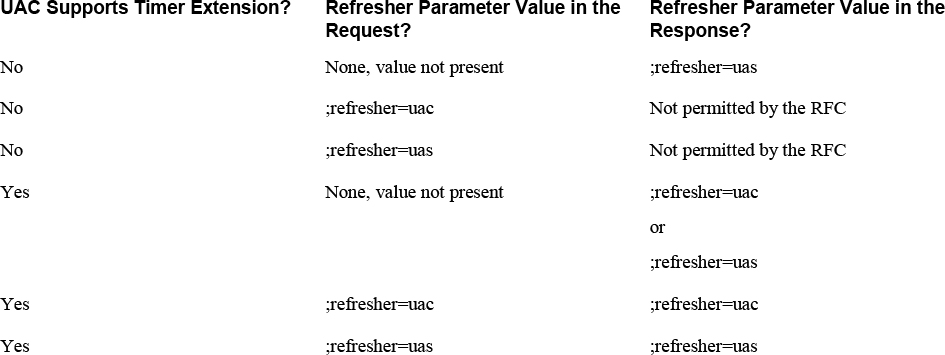
After a session has been established with a defined session interval and a designated session refresher, the timer starts for the session. At some point during the session—normally at the midway point, as per the RFC 4028 recommendation—the designated refresher sends either a re-INVITE message or an UPDATE message, which operates exactly the same as in the earlier examples in this section. Only a 200 OK response to a session refresh request can extend the session. Failure to properly negotiate this session refresh can lead to premature call failure at the session refresh interval rather than the session timer expiration. One example of this type of failure would be the refresher modifying the SDP through the session refresh. If this modification is not accepted by the other devices in the session, the call can be terminated on the spot. Figure 9-32 shows both a successful session refresh and a refresh that fails due to the session refresh being rejected.

Figure 9-32 Good and Bad Session Refresh Attempts Between a UAC and a UAS
The inclusion of a session timer is entirely optional. The absence of a Session-Expires header means the user agent wants the session to be infinite, or without a definite end. The Session-Expires header can be removed mid-call during a session refresh, which results in further session refreshing being disabled because the new session timer is now infinite.
Tip
Any mid-call signaling UPDATE message or re-INVITE message sent for a purpose other than a session refresh may also contain session timer parameters. These offers/answers also refresh the session if they occur as per the specifications defined in RFC 4028.
It is very important for an SBC to have the ability to interwork and pass session refreshes on all call legs requiring that the session timer be updated. Failure to comply can lead to call failures and premature disconnects. It may also be possible for an SBC to have one call leg without a session timer and another call leg with a session timer. An SBC must be able to maintain session timers across different SIP dialogs in order to avoid session timeout events and unwanted session termination.
CUBE can facilitate session interval interworking across different call legs by default without any configuration. The command shown in Example 9-25 illustrates how to enable session refresh interworking on CUBE. In addition, the Min-Se and Session-Expires timer can be configured on CUBE if something outside the default value is required, as shown in Example 9-26.
Example 9-25 Configuring CUBE Session Refresh
voice service voip
 sip
session refresh
Example 9-26 Configuring CUBE Session Timers
voice service voip
 sip
min-se 1800 session-expires 1800
Managing Mid-call Signaling
The previous sections discuss many different instances in which mid-call signaling is required for established communication sessions. Due to the number of different types of mid-call signaling needed and methods used to accomplish these tasks, there is a possibility of interoperability events occurring during mid-call signaling. An SBC must be able to handle complex mid-call signaling events across many different call legs and facilitate signaling interworking for many different types of mid-call signaling permutations and combinations. An SBC lacking the ability to properly interwork mid-call signaling can lead to vendor interoperability, call failures, and session establishment issues.
By default, CUBE interworks and passes through all mid-call signaling from one call leg to another. However, in many cases, passing across all mid-call signaling messages end-to-end is a hindrance. Reducing the number of mid-call signaling messages end-to-end often promotes smooth interoperability across device types and networks.
CUBE provides the ability to consume all mid-call signaling and to handle such signaling locally instead of passing it across to the peer call leg. This flavor of mid-call signaling is activated using the midcall-signaling block command. Figure 9-33 illustrates the application and operation of this command on CUBE.

Figure 9-33 CUBE Blocking All Mid-Call Signaling
While handling all mid-call signaling natively presents a drastic improvement in terms of reducing the number of message exchanges end to end and speeding up transaction establishment times, it may lead to unexpected behavior and call failures as well. Consider a situation in which two video-capable endpoints establish an audio-only session across CUBE by using midcall-signaling block. With this command, neither of these devices would be able to escalate the audio-only session into an audio and video session. This is because CUBE blocks any and all mid-call signaling. The re-INVITE for video escalation would be consumed by CUBE, which would result in no video due to the failure of the video escalation operation.
Tip
Session refresh messages can also be blocked by the midcall-signaling block command. It is best to avoid using this command if session interval timers are being used as these are required to keep a session established.
To provide the flexibility of natively handling most mid-call signaling while at the same passing across certain mid-call signaling transactions that need to be transmitted end to end, CUBE provides the midcall-signaling passthru media-change command. With this command in place, only mid-call signaling transactions that alter the media characteristics of the communication session are passed through. These characteristics include codec changes and addition and modification of media types (for example, audio, video, image) to the communication session.
Changes to the media direction attribute (a=) and the connection data information field (c=) of the SDP do not qualify as sufficient conditions to pass across the message end to end. This is the case, for example, if a session is established between two endpoints with bidirectional G.711ulaw audio and one party places the call on hold. As described earlier in this chapter, the device placing the session on hold may send a re-INVITE message with a=sendonly, while the audio codec remains G.711ulaw. This re-INVITE message would not be passed through CUBE with midcall-signaling passthru media-change present as the change in media direction does not qualify as an event that needs to be passed through to the peer call leg. Figure 9-34 details a scenario with midcall-signaling passthru media-change in which the original call was established as a G.711ulaw audio-only session, and the session was then put on hold briefly before returning. This hold is blocked for the reasons just explained. Finally, the session is escalated to include video along with audio. Because CUBE considers this a valid media change, the re-INVITE message is passed to the peer call leg.
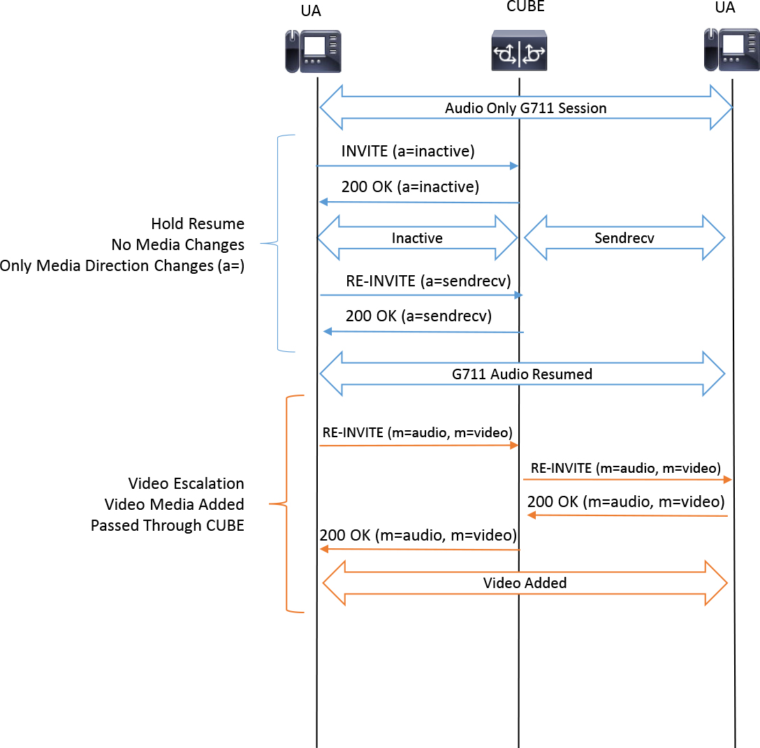
Figure 9-34 CUBE Passing Mid-call Signaling with Media Changes
SIP Authentication with CUBE
CUBE is often located on the edge of the enterprise network, acting as a demarcation point between the local enterprise LAN and other public networks. This means CUBE must be extra cautious when receiving session establishment requests and must verify that the user agent initiating a request is a trusted entity, especially if connected to the public Internet. In a similar vein, CUBE must be able to respond to authentication requests from other devices when attempting to establish outbound sessions. Failure to do either of these actions could result in call failure or even fraudulent calls being proxied through CUBE from an unknown source toward the enterprise or ITSP. The different types of authentication for inbound and outbound session creation fall into a few broad categories, as discussed in the next few sections.
Toll Fraud Prevention
The first line of protection enforced by CUBE is toll fraud. This feature allows you to create a static list of IPv4 and IPv6 addresses that are permitted to send SIP requests to CUBE. A dynamic list of IP addresses is also gathered from the session target commands on configured dial peers. Every incoming SIP request packet received by CUBE is evaluated to verify that the source IP address of the SIP packet was in fact a trusted source. CUBE evaluates the Layer 3 source IP address rather than the Via or Contact header as these are much easier to spoof. If the IP address is not trusted, CUBE silently drops the packet and never generates a response. You can change this behavior by removing the command silent-discard untrusted, as shown in Example 9-27.
Example 9-27 Disabling the Silent Discard of Untrusted SIP Messages
voice service voip
 sip
  no silent-discard untrusted
To configure an IP address or range of IP addresses for trusted authentication checks, use the syntax shown in Example 9-28. The first two values define a /24 or 255.255.255.0 subnet mask for the 14.50.214.0 and 14.50.215.0 subnets. The last entry defines a single trusted IP address. CUBE also dynamically adds IP information for a session target to the trusted list, so you do not have to configure this. Example 9-28 also shows a dial peer defined with session target ipv4:172.18.110.48, which will be added to the trusted list dynamically, as shown in Example 9-29.
![]()
Example 9-28 Defining an IP Trusted List with CUBE
voice service voip
 ip address trusted authenticate
 ip address trusted list
  ipv4 14.50.214.0 /24
  ipv4 14.50.215.0 255.255.255.0
  ipv4 14.50.216.10
!
dial-peer voice 11 voip
 session protocol sipv2
 session target ipv4:172.18.110.48
To view the current list of statically configured and dynamically trusted sourced gleaned from dial peer session target commands, you can issue the command show ip address trusted list, as shown in Example 9-29. As you can see, if silent discard is disabled, the call-reject reason 21 is used to generate a 403 Forbidden SIP response.
Example 9-29 Trusted List Verification on CUBE
Router# show ip address trusted list
IP Address Trusted Authentication
 Administration State: UP
 Operation State:      UP
IP Address Trusted Call Block Cause: call-reject (21)
VoIP Dial-peer IPv4 and IPv6 Session Targets:
Peer Tag        Oper State      Session Target
--------        ----------      --------------
11              UP              ipv4:172.18.110.48
Configured IP Address Trusted List:
ipv4 14.50.214.0 255.255.255.0
ipv4 14.50.215.0 255.255.255.0
ipv4 14.50.216.10
Dynamic IP Address Trusted List:

IP Address                                   Subnet Mask     Count Reason
-------------------------------------------- --------------- ----- --------
Note
CUBE does not currently support DNS-based authentication for fully qualified domain names configured on session targets. The resolvable IP addresses must be statically configured to avoid toll fraud rejection.
Note
Chapter 10 goes into further detail about toll fraud operation for Unified CME registered SIP phones that will make use of the Dynamic IP Address Trusted List section of the show ip address trusted list command.
SIP Trunk Registration
CUBE may be required to register with a service provider and maintain a valid registration status in order to send calls or receive calls from a provider. Without this registration in place, the service provider may not deliver inbound calls to CUBE or may reject outbound calls from CUBE. CUBE can register to a service provider with sip-ua or to multiple service providers using voice class tenant commands. Multi-tenant CUBE configurations are beyond the scope of this book, but the commands applied to sip-ua are applicable to voice class tenants.
When configuring SIP registration, you must know some key information that is required for a valid handshake to complete:
• The username assigned to the SIP trunk that will be sent when a challenge response is received
• The password that will be used to create the www-authenticate response to the challenge
• The SIP target of registration in order to send REGISTER messages
• The SIP realm that will be used for a username/password lookup
From a high level, a valid SIP registration looks like the handshake outlined in Figure 9-35. In this illustration, CUBE generates a REGISTER request toward the service provider. The service provider responds with a 401 Unauthenticated response and includes the special header WWW-Authenticate. This header field is used to indicate that CUBE should retry the request and supply a digest authentication response for the given case-sensitive realm. Noted that for security reasons, the actual password is not sent in plaintext. SIP leverages the HTTP digest authentication scheme from RFC 2069 and 2617, which involves generating an MD5 hash using the inputs from the WWW-Authenticate header along with locally known values such as the username and password. With the MD5 digest authentication response generated, CUBE then sends a new REGISTER message with the Authentication header containing the MD5 hash response and other required information for the MD5 hash computation. Upon reception of the new REGISTER message with the Authorization header, the service provider performs the same MD5 computations using the supplied inputs. If the service provider’s MD5 hash calculation matches the value found in the Authorization header’s response field, the provider responds with a 200 OK message to confirm that the trunk is now registered.
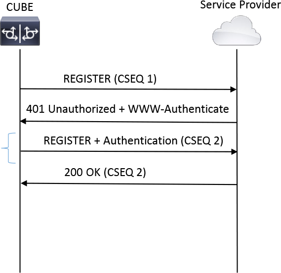
Figure 9-35 Valid REGISTER Handshake
To configure registration via sip-ua or a voice class tenant, simply define the three configuration items shown in Example 9-30. The registrar command is used to define the IP address of the registration target. The authentication and credentials commands allow CUBE to match the case-sensitive realm of the 401 Unauthenticated message and generate a new REGISTER using the proper username and password.
Example 9-30 A Sample CUBE Registration Configuration Along with CUBE Debugging for the Same Call
### Sample Configuration:
!
sip-ua
 registrar ipv4:172.18.110.88
 credentials username cisco password 0 cisco123 realm kydavis.cisco.com
 authentication username cisco password 0 cisco123 realm kydavis.cisco.com
!
### CUBE Debugging
Sent:
REGISTER sip:172.18.110.88:5060 SIP/2.0
Via: SIP/2.0/UDP 172.18.110.58:5060;branch=z9hG4bK3A25A
From: <sip:[email protected]>;tag=58551EB-18AA
To: <sip:[email protected]>
Call-ID: 762A1E52-206111EA-FFFFFFFF8024D377-FFFFFFFF8EBB74CF
User-Agent: Cisco-SIPGateway/IOS-17.1.1
Max-Forwards: 70
Timestamp: 1576627755
CSeq: 1 REGISTER
Contact: <sip:[email protected]:5060>
Expires:  3600
Supported: path
Content-Length: 0

Received:
SIP/2.0 401 Unauthorized
Via: SIP/2.0/UDP 172.18.110.58:5060;branch=z9hG4bK3A25A
From: <sip:[email protected]>;tag=58551EB-18AA;tag=1
To: <sip:[email protected]>;tag=1
Call-ID: 762A1E52-206111EA-FFFFFFFF8024D377-FFFFFFFF8EBB74CF
CSeq: 1 REGISTER
WWW-Authenticate: DIGEST qop="auth",nonce="Xj504f7xvTnog37qBW",realm="kydavis.cisco.com",algorithm=MD5
Content-Length: 0

Sent:
REGISTER sip:172.18.110.88:5060 SIP/2.0
Via: SIP/2.0/UDP 172.18.110.58:5060;branch=z9hG4bK3B644
From: <sip:[email protected]>;tag=58551EB-18AA
To: <sip:[email protected]>
Call-ID: 762A1E52-206111EA-FFFFFFFF8024D377-FFFFFFFF8EBB74CF
User-Agent: Cisco-SIPGateway/IOS-17.1.1
Max-Forwards: 70
Timestamp: 1576627755
CSeq: 2 REGISTER
Contact: <sip:[email protected]:5060>
Expires: 3600
Supported: path
Authorization: Digest username="cisco",realm="kydavis.cisco.com",uri="sip:172.18.110.88:5060",response="49a342f8858d8824b356b7fec8e2972a",nonce="Xj504f7xvTnog37qBW",cnonce="A2743717",qop=auth,algorithm=MD5,nc=00000001
Content-Length: 0

Received:
SIP/2.0 200 OK
Via: SIP/2.0/UDP 172.18.110.58:5060;branch=z9hG4bK3B644
From: <sip:[email protected]>;tag=58551EB-18AA
To: <sip:[email protected]>;tag=2
Call-ID: 762A1E52-206111EA-FFFFFFFF8024D377-FFFFFFFF8EBB74CF
CSeq: 2 REGISTER
Contact: <sip:172.18.110.88:5060;transport=UDP>;expires=3600
Content-Length: 0
Example 9-30 also includes a set of sample debugging outputs that align with the signaling shown in Figure 9-35. Notice that the first REGISTER message sent with CSEQ 1 is rejected by the UAS with a 401 Unauthorized that contains the WWW-Authenticate header. CUBE performs a lookup of the available CLI options using the realm found in this header. The sample configuration in this case has a matching realm, and the username and password are leveraged as inputs for the response generation. (So are other values from the WWW-Authenticate header, such as the nonce and SIP Request-URI header. Note that the nonce is a random value selected by the server to help defend against reply attacks.) CUBE then sends a new REGISTER message with CSEQ 2 and includes the Authorization header. This header includes the generated response value along with some information the server should use when performing its own calculation, such as the cnonce (client nonce), which serves a similar purpose to the server nonce received in the 401 earlier in the session. The server returns a 200 OK after the calculation of the MD5 response matches the response sent in the SIP header.
Tip
You can use registrar dns: when the service provider uses DNS redundancy. It is important to ensure proper DNS configuration to enable CUBE to resolve the FQDN configured on the registrar command. Please refer to Chapter 8, “CUBE Call Routing and Digit Manipulation,” for information about DNS Configuration on CUBE.
When troubleshooting REGISTER messages, you can use the special debugging command debug ccsip non-call, along with debug ccsip messages, to view SIP messaging that is not related to calls. The command show sip-ua register status can be issued to view the status of all configured registrar indexes. The values can be observed in Example 9-31. The Line column references the username or number configured, and the expires column details how long until a new reregistration handshake occurs. Finally, the reg column provides a simple yes or no for registration status.
Example 9-31 Verifying Registration Status on CUBE
CUBE# show sip-ua register status
--------------------- Registrar-Index  1 ---------------------
Line                             peer      expires(sec) reg survival  P-Associ-URI
================================ ========= ============ === ========  ============
myusername                       -1        213          yes normal
SIP Digest Authentication
Like SIP trunk registration, discussed in the previous section, SIP digest authentication may be requested by a service provider when attempting to establish a session through the service provider network. This may occur in tandem with SIP trunk registration as added security or as a standalone authentication method. Figure 9-36 illustrates a standard SIP handshake with digest authentication. The main difference between this handshake and the one shown in Figure 9-35 is that the 401 Unauthorized message with a WWW-Authenticate header is sent in response to the INVITE rather than a REGISTER request. CUBE handles the 401 in this scenario exactly the same as in the previous example. CUBE attempts to find username/password information based on the case-sensitive realm found in the www WWW-Authenticate header. Once it is found, CUBE creates a new INVITE message with an Authentication header. If the username/password is accepted, the call proceeds normally.
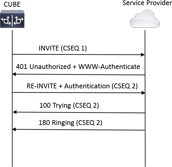
Figure 9-36 A Sample Ad Hoc INVITE Authentication Handshake
SIP Header–Based Authentication
As mentioned in Chapter 8, some providers require that specific headers or even specific phone numbers be sent in the SIP INVITE request. The presence of these headers is enough to authenticate the call and allow the session to be established. If a custom header or a specific formatted header is required, SIP profiles can be leveraged to modify the header in a SIP INVITE message sent to the ITSP. (See Chapter 8 for more information on SIP header modification.)
For inbound INVITE messages sent to CUBE, the host IP or FQDN in the Request-URI header is examined to verify that it matches a valid IP address configured on CUBE. For FQDN entries, the sip-ua command permit hostname must be configured to perform a valid lookup. Example 9-32 shows a sample debug ccsip error command output and the applicable configuration used to define FQDN permission.
Example 9-32 Debugging and Configuration Showing FQDN Validation on CUBE
! Debugs
Oct 1 16:20:34.547: //-1/xxxxxxxxxxxx/SIP/Error/sipSPI_validate_own_ip_addr:
ReqLine IP addr does not match with host IP addr
! Configuration
sip-ua
 permit hostname dns:rtp-cube.ccnpcollab.lab
!
Media Interworking
The types of audio and video codecs supported in a customer’s Unified CM network often depend on a few factors:
• The capabilities of the endpoints, such as desktop phones and soft clients that will be handling calls
• The capabilities of applications that will be tasked with performing call treatment functions, such as interactive voice response (IVR) systems, call queueing, and MOH or other messages played to a caller
• The capabilities of third-party devices, including the ITSP or other collaboration systems
Evaluating these three factors for a common audio and video codec can be a laborious task, and it increases as the enterprise grows. On the edge of the network, CUBE can exert control over the signaling exchanged between endpoints and can influence the negotiation of media. Taking the interworking one step further, CUBE has the ability to exert control over the media stream itself and may perform media interworking functions for RTP audio or DTMF Relay. The next sections of this chapter discuss the ways CUBE can accomplish media interworking at both the signaling and media planes.
Audio Codec Interworking
The most common type of session established through CUBE is an audio-only media session. Depending on the country and endpoint settings, various audio codecs could be advertised. CUBE works to filter unsupported and unconfigured audio codecs between the inbound and outbound call legs in order to find a suitable common codec that satisfies both parties. The next few sections detail how audio codec interworking is performed on CUBE.
Dial Peer Codecs
CUBE leverages the dial peer codec command to enable a single audio codec for support on a dial peer. The absence of any codec command indicates support for the default audio codec, g729r8. Example 9-33 shows how to change the audio codec to g711ulaw in addition to the supported audio codecs on CUBE. The most common audio codecs have been highlighted to stand out in this example.
![]()
Example 9-33 Dial Peer Audio Codec Configuration
CUBE(config)# dial-peer voice 1000000 voip
CUBE (config-dial-peer)# codec g711ulaw
CUBE (config-dial-peer)# codec ?
  aacld          AACLD 90000 bps
  clear-channel  Clear Channel 64000 bps (No voice capabilities: data transport only)
  g711alaw       G.711 A Law 64000 bps
  g711ulaw       G.711 u Law 64000 bps
  g722-48        G722-48K 64000 bps - Only supported for H.320<->H.323 calls
  g722-56        G722-56K 64000 bps - Only supported for H.320<->H.323 calls
g722-64 G722-64K 64000 bps
  g723ar53       G.723.1 ANNEX-A 5300 bps (contains built-in vad that cannot be disabled)
  g723ar63       G.723.1 ANNEX-A 6300 bps (contains built-in vad that cannot be disabled)
  g723r53        G.723.1 5300 bps
  g723r63        G.723.1 6300 bps
  g726r16        G.726 16000 bps
  g726r24        G.726 24000 bps
  g726r32        G.726 32000 bps
  g728           G.728 16000 bps
  g729br8        G.729 ANNEX-B 8000 bps (contains built-in vad that cannot be disabled)
  g729r8         G.729 8000 bps
gsmamr-nb GSM AMR-NB 4750 - 12200 bps (contains built-in vad that cannot be disabled)
  ilbc           iLBC 13330 or 15200 bps
  isac           iSAC 10 to 32 kbps (variable bit-rate)
mp4a-latm MP4A-LATM upto 128 kbps
opus Opus upto 510 kbps
transparent transparent; uses the endpoint codec
When enabling g729 audio codecs on a dial peer, the command g729 annexb-all should be configured to allow CUBE to properly handle and interwork different variants of g729. The configuration in Example 9-34 involves this simple one-line command. If this command is not present, call setup involving differing variants of g729 may fail with a 488 Not Acceptable Media and cause code 65.
Example 9-34 Enabling All g729 Audio Flavors
voice service voip
 sip
  g729 annexb-all
Table 9-5 is a handy reference guide for the common audio codec SDP attributes and the configuration required on a dial peer to enable these codecs. The bytes command can be postfixed to control the packetization rate for a given audio codec. For example, codec g711ulaw bytes 160 sets the packetization rate of G.711ulaw as 20 ms. The bytes command can be omitted to assume the default payload size. For a full list of audio codec packetization rates, bandwidth consumption, and other information, see https://www.cisco.com/c/en/us/support/docs/voice/voice-quality/7934-bwidth-consume.html.
![]()
Table 9-5 SDP Reference Table for the Dial Peer Codec Commands
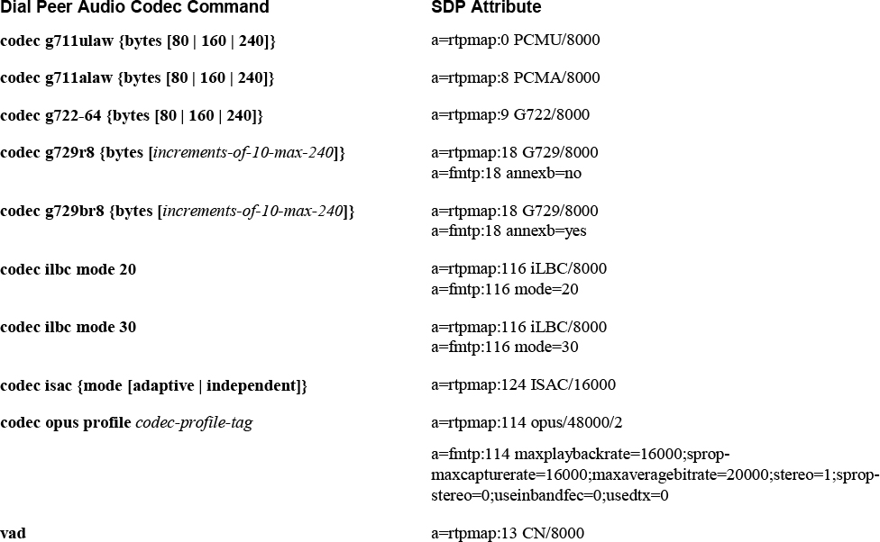
Note
Voice activity detection (VAD) is included in Table 9-5 because it is negotiated with other audio codecs. To disable VAD, simply remove it with the command no vad on the applicable dial peer.
The payload types iLBC, iSAC, and OPUS are in the dynamic range. Refer to RFC 3551 (or Chapter 3) for the list of static SDP payload types. The values included in Table 9-5 are the dial peers’ default payload types. OPUS was added in IOS-XE 17.3 and with that change the rtp payload-type of 114 was repurposed from the AACLD audio codec, which is now changed to the rtp payload-type of 112. Similarly, when configuring the codec command with OPUS the codec profile must be configured to define the a=fmtp parameters detailed in RFC 7587. The codec profile configurations will be sent when CUBE is responsible for creating an offer, usually a delayed offer to early offer scenario. In early offer to early offer scenarios CUBE will pass through the received a=fmtp parameters from the inbound call leg to the outbound call leg. The syntax for configuring and applying OPUS on a dial peer and the applicable codec profile are shown in Example 9-35. Similar codec profile configuration can be used to define clock-rate and fmtp parameters for the other audio codecs such as AACLD and MP4A-LATM or video codecs such as H.263+ and H.264.
Example 9-35 OPUS Configuration on CUBE
!
codec profile 1 opus
 fmtp “fmtp:114 maxplaybackrate=16000;sprop-maxcapturerate=16000;maxaveragebitrate=20000;stereo=1;sprop-stereo=0;useinbandfec=0;usedtx=0"
!
dial-peer voice 777 voip
 destination-pattern 123456789
 session protocol sipv2
 session target dns:rtp-cucm.ccnpcollab.lab
codec opus profile 1
!
Codec Filtering
As mentioned in Chapter 8, when processing a call, outbound dial peers are filtered to those that have a common audio codec for the session as the audio codec on the inbound dial peer. The offer sent by CUBE using the selected outbound dial peer contains a filtered list of common audio codecs. If no matching audio codec is found and there is no Local Transcoding Interface (LTI) transcoder, the call fails. We’ll discuss LTI transcoders further in a moment, but first Figure 9-37 illustrates how CUBE filters dial peers and codecs when performing inbound and outbound dial peer matching. The following steps occur in this process:
![]()
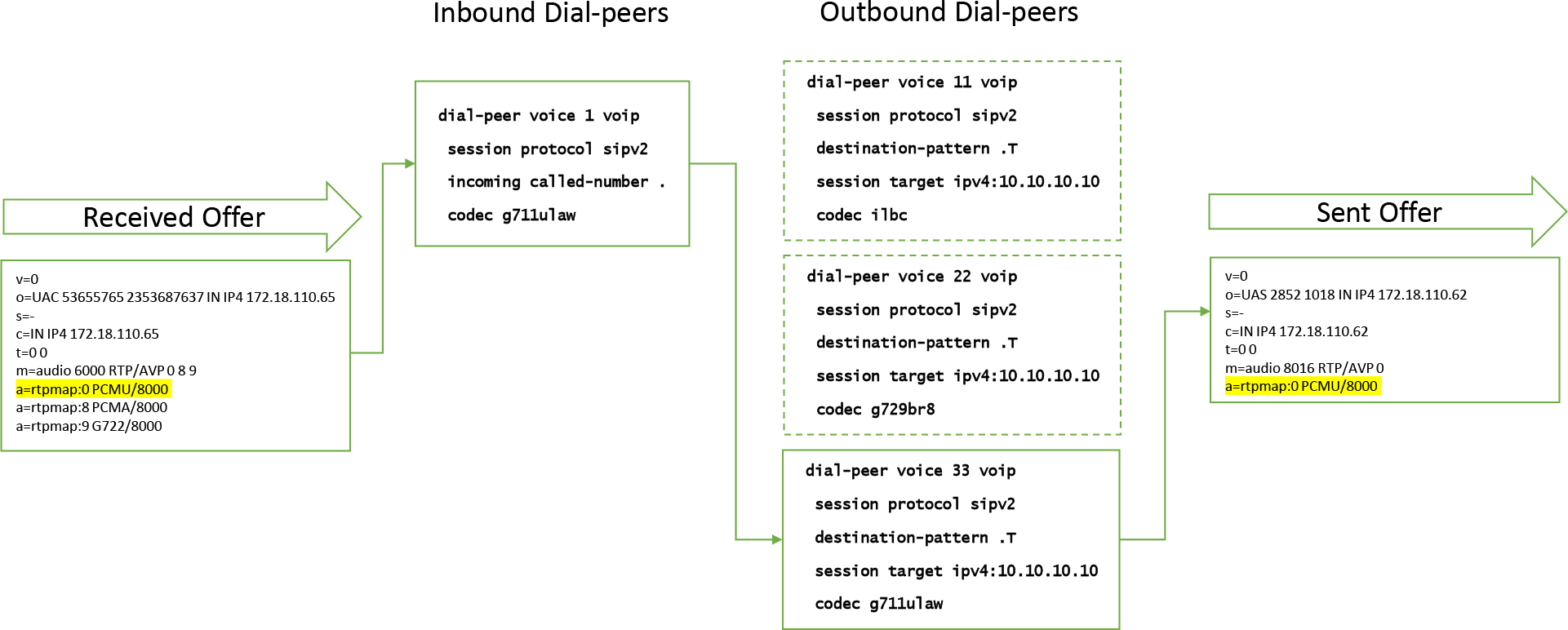
Figure 9-37 CUBE Dial Peer and Offer Filtering
Step 1. An SDP offer with g711ulaw, g711alaw, and g722 is received. There is only one inbound dial peer in this example to keep things simple, and this dial peer contains the codec g711ulaw.
Step 2. Dial peer 1 is selected as the inbound dial peer because it is the only available incoming dial peer and also happens to contain a matching audio codec.
Step 3. The outbound dial peers are all equal in configuration; that is, they have the same commands configured. The delta is the audio codec configuration.
Step 4. After the outbound dial peer match is made, CUBE filters the original offer list of g711ulaw, g711alaw, and g722 based on the inbound dial peer match with g711ulaw that is configured. This filtering means that only dial peer 33 with g711ulaw can be selected because the others do not have a codec command that matches the inbound dial peer or inbound offer.
Step 5. An offer that contains only g711ulaw is created and sent on the outbound call leg.
Step 6. The call proceeds normally.
When a delayed offer INVITE message is received, CUBE selects the best matching inbound dial peer, as detailed in Chapter 8, but the outbound dial peer list is still filtered. For example, if Figure 9-37 showed delayed offer and dial peer 1 were still selected, the assumed audio codec would be g711ulaw, as per that inbound dial peer’s configuration. As a result, Dial Peer 33 is the only eligible outbound dial peer with g711ulaw. No offer can be sent if this is a delayed offer interworking call, but if early offer is being forced with the early-offer forced command, an offer with g711ulaw would be sent.
Voice Class Codecs
With many different endpoints on a network that have different capabilities, you might need to accept or send offers with more than one audio codec. Depending on the number of codecs, it might be a large administrative task to create multiple dial peers with a single audio codec command. Fortunately, CUBE allows you to use the voice class codec command to create a list of supported codecs and then apply this list to a dial peer. Example 9-36 shows how to configure a voice class codec with two supported codecs. The same audio codecs found on a dial peer can be found in a voice class codec.
![]()
Example 9-36 Voice Class Codec Configuration Example
CUBE(config)# voice class codec 1
CUBE (config-class)# codec preference ?
  <1-24>  Priority order (1 = Highest)

CUBE (config-class)# codec preference 1 ?
  aacld          AACLD 90000 bps
  clear-channel  Clear Channel 64000 bps (No voice capabilities: data transport only)
  g711alaw       G.711 A Law 64000 bps
  g711ulaw       G.711 u Law 64000 bps
  g722-48        G722-48K 64000 bps - Only supported for H.320<->H.323 calls
  g722-56        G722-56K 64000 bps - Only supported for H.320<->H.323 calls
  g722-64        G722-64K 64000 bps
  g723ar53       G.723.1 ANNEX-A 5300 bps (contains built-in vad that cannot be disabled)
  g723ar63       G.723.1 ANNEX-A 6300 bps (contains built-in vad that cannot be disabled)
  g723r53        G.723.1 5300 bps
  g723r63        G.723.1 6300 bps
  g726r16        G.726 16000 bps
  g726r24        G.726 24000 bps
  g726r32        G.726 32000 bps
  g728           G.728 16000 bps
  g729br8        G.729 ANNEX-B 8000 bps (contains built-in vad that cannot be disabled)
  g729r8         G.729 8000 bps
  gsmamr-nb      GSM AMR-NB 4750 - 12200 bps (contains built-in vad that cannot be disabled)
  ilbc           iLBC 13330 or 15200 bps
  isac           iSAC 10 to 32 kbps (variable bit-rate)
  mp4a-latm      MP4A-LATM upto 128 kbps
  opus           OPUS upto 510 kbps
  transparent    transparent; uses the endpoint codec

Router(config-class)# codec preference 1 g711ulaw
Router(config-class)# codec preference 2 g722-64

Router# show run | section voice class codec 1
voice class codec 1
 codec preference 1 g711ulaw
 codec preference 2 g729br8
Voice class codecs are assigned to a dial peer in much the same way codecs are assigned with a normal codec command. Example 9-37 shows the command required to add a voice class codec to a dial peer. This command can be used on either inbound or outbound dial peers to influence answers and offers on CUBE.
Example 9-37 Application of a Voice Class Codec on a Dial Peer
dial-peer voice 1000000 voip
 voice-class codec 1
Just as with the regular codec command, voice-class codec is used to filter dial peer matching and influence egress offers from CUBE. Using Figure 9-38 to illustrate the point, the codecs in Figure 9-37 have been consolidated into applicable voice class codec commands:
• The first voice class codec contains g711ulaw and g711alaw.
• The second voice class codec contains ilbc and isac.
• One of each voice class codec has been applied to the inbound and outbound dial peers.
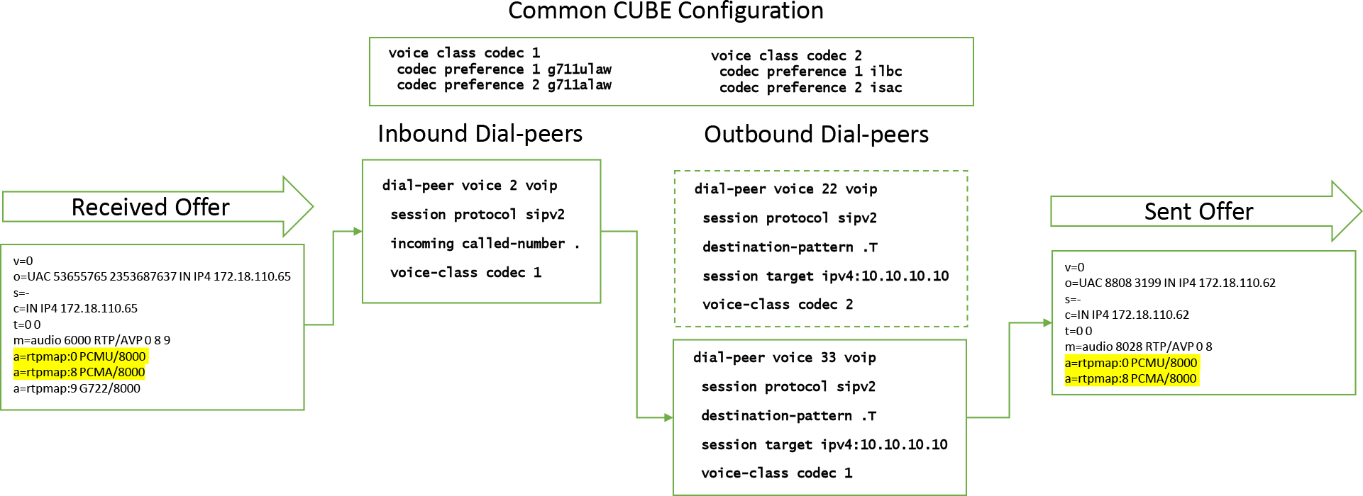
Figure 9-38 Incoming Offer and Dial Peer Filtering with Voice Class Codecs
The following process occurs in Figure 9-38:
Step 1. The inbound call legs offer contains g711ulaw, g711alaw, and g722.
Step 2. Incoming Dial Peer 2 contains an incoming match statement and applicable codecs for the call, so this is selected as the inbound dial peer.
Step 3. Outbound dial peers are evaluated, based on the inbound dial peer’s codec support, and dial peer codec filtering occurs. This is an easy visual exercise since Dial Peer 22’s voice class codec does not contain any common codecs with the offer or the inbound dial peer. This leaves only Dial Peer 33 as an eligible outbound dial peer.
Step 4. An outbound offer is created by CUBE, and the list of codecs in the offer is filtered to those that match the inbound offer, inbound dial peer, and outbound dial peer configuration. Thus g711ulaw and g711alaw are send in the offer, and g722 is filtered out.
Step 5. The call proceeds normally from here.
CUBE LTI Transcoder
A CUBE equipped with digital signal processors (DSPs) can leverage the dspfarm feature to perform audio codec interworking when a mismatch occurs. In contrast to the SCCP-based dspfarms commonly leveraged by Unified CM, CUBE-based dspfarms use the Local Transcoding Interface (LTI) and are often referred to as LTI transcoders. This type of transcoder registers directly to CUBE and can be used for transcoding. Transcoding is the act of converting the audio payload of RTP packets from one codec to another. An example of transcoding would be the modification of g711ulaw RTP packets into g729br8 RTP packets.
The configuration required to register an LTI transcoder to CUBE is fairly simple:
Step 1. Verify which DSP resources are going to be used for DSP farming by using applicable show commands, such as show platform or show inventory.
Step 2. Configure the DSP voice cards for DSP farming in order to create a pool of DSP resources for allocation in later steps.
Step 3. Define dspfarm transcoding profiles with unique numeric tags:
• Assign or remove audio codecs that the transcoder will interwork.
• Define the maximum number of sessions this transcoder will handle at any given time.
• Associate the transcoder to the CUBE application.
• Enable the transcoder for registration with the no shutdown command.
Example 9-38 shows the commands required to register an LTI transcoder to CUBE. The example first shows the verification that a DSP is installed on the motherboard via the show inventory command. Next, the voice card in slot 0/4, as gleaned from the show inventory command, must be enabled for DSP farming with the command dsp services dspfarm. Next, transcoders can be configured because a virtual pool of DSP resources has been created. A transcoder has two different variants, which influence the operation and capabilities of the transcoder:
• Standard transcoder: Can transcode g711 to any other type of codec. One call leg must always be g711.
• Universal transcoder: Can transcode any codec to any other codec. Does not require either call leg to use the g711 codec.
In Example 9-38, the universal postfix was omitted from dspfarm profile 1 transcode, which means it is a standard transcoder. Each transcoder needs to define the maximum number of sessions that it can allocate. The actual number is derived dynamically from an algorithm that considers the current pool allocation from all other configured dspfarms and the types of codecs configured on the transcoder. By issuing a question mark (?) after maximum sessions, you can see the real-time maximum for the profile. To adjust the number, you can either free up resources on other dspfarms or remove codecs from the dspfarm being configured. Next, the dspfarm is associated with the CUBE application and enabled with no shutdown.
The second dspfarm profile in Example 9-38 shows a similar configuration but with two main differences. The first is that this is a universal transcoder, as indicated by the universal postfix. Second, the max sessions command shows a lower number than the previous issuing of the command. This shows the new dynamic number of maximum sessions, taking into account the first configured dspfarm. The default audio codecs for a transcoder are g729abr8, g729ar8, g711ulaw, and g711alaw. New codecs can be added with the command codec audio-codec on the transcoder or codecs can be removed by prefixing no before the codec command. The question mark (?) can be used to view all audio codecs supported by the dspfarm.
Example 9-38 Configuration Steps for LTI Transcoders
sj-cube# show inventory
NAME: “PVDM subslot 0/4", DESCR: “PVDM4-64 Voice DSP Module"
PID: PVDM4-64          , VID: V02  , SN: FOC22170MPH

sj-cube(config)# voice-card 0/4
sj-cube(config-voicecard)# dsp services dspfarm
sj-cube(config-voicecard)# exit

sj-cube(config)# dspfarm profile 1 transcode ?
  universal  Profile type Transcoding
  <cr>       <cr>

sj-cube(config)# dspfarm profile 1 transcode
sj-cube(config-dspfarm-profile)# max sessions ?
  <1-48>  Number of sessions assigned to this profile

sj-cube(config-dspfarm-profile)# max sessions 10
sj-cube(config-dspfarm-profile)# associate application CUBE
sj-cube(config-dspfarm-profile)# no shutdown
sj-cube(config-dspfarm-profile)# exit

sj-cube(config)# dspfarm profile 2 transcode universal
sj-cube(config-dspfarm-profile)# max sessions ?
  <1-31>  Number of sessions assigned to this profile

sj-cube(config-dspfarm-profile)# max sessions 10
sj-cube(config-dspfarm-profile)# associate application CUBE
sj-cube(config-dspfarm-profile)# no shutdown

sj-cube(config-dspfarm-profile)# codec ?
  g711alaw      G.711 A Law 64000 bps
  g711ulaw      G.711 u Law 64000 bps
  g722-64       G722r64
  g729abr8      G.729ab 8000 bps
  g729ar8       G.729a 8000 bps
  g729br8       G.729b 8000 bps
  g729r8        G.729 8000 bps
  gsmamr-nb     GSMAMR NB codec
  ilbc          ILBC codec
  isac          ISAC codec
  pass-through  Stream Pass Through
Note
codec pass-through is a special configuration that allows for non-audio codecs to be passed seamlessly through the transcoder. This should be used when T.38 faxing or video is an option for session negotiation.
With the initial configuration out of the way, Example 9-39 shows the default codecs found on a dspfarm in addition to the show dspfarm all command, which has been truncated here to detail the outputs relevant to dspfarm 1. This show command confirms that the DSP is up, active, and associated to the CUBE application. With these dspfarms in place, CUBE can now perform media interworking for call legs that do not contain a common audio codec.
Example 9-39 Verification for LTI Transcoders
sj-cube# show run | section card|dspfarm
voice-card 0/4
 dsp services dspfarm
!
dspfarm profile 1 transcode
 codec g729abr8
 codec g729ar8
 codec g711alaw
 codec g711ulaw
 maximum sessions 10
 associate application CUBE
!
dspfarm profile 2 transcode universal
 codec g729abr8
 codec g729ar8
 codec g711alaw
 codec g711ulaw
 maximum sessions 10
 associate application CUBE

sj-cube# show dspfarm all
Dspfarm Profile Configuration

 Profile ID = 1, Service = TRANSCODING, Resource ID = 1
 Profile Service Mode : Non Secure
 Profile Admin State : UP
 Profile Operation State : ACTIVE
 Application : CUBE   Status : ASSOCIATED
 Resource Provider : FLEX_DSPRM   Status : UP
 Total Number of Resources Configured : 10
 Total Number of Resources Available : 10
 Total Number of Resources Out of Service : 0
 Total Number of Resources Active : 0
 Codec Configuration: num_of_codecs:4
 Codec : g711ulaw, Maximum Packetization Period : 30
 Codec : g711alaw, Maximum Packetization Period : 30
 Codec : g729ar8, Maximum Packetization Period : 60
 Codec : g729abr8, Maximum Packetization Period : 60
Dspfarm Profile Configuration
[..truncated..]
SLOT   DSP VERSION  STATUS CHNL USE   TYPE    RSC_ID BRIDGE_ID PKTS_TXED PKTS_RXED

0/4    1   52.4.0   UP     N/A  FREE  xcode   1      -         -         -
0/4    1   52.4.0   UP     N/A  FREE  xcode   1      -         -         -
0/4    1   52.4.0   UP     N/A  FREE  xcode   1      -         -         -
0/4    1   52.4.0   UP     N/A  FREE  xcode   1      -         -         -
0/4    1   52.4.0   UP     N/A  FREE  xcode   1      -         -         -
0/4    1   52.4.0   UP     N/A  FREE  xcode   1      -         -         -
0/4    1   52.4.0   UP     N/A  FREE  xcode   1      -         -         -
0/4    1   52.4.0   UP     N/A  FREE  xcode   1      -         -         -
0/4    1   52.4.0   UP     N/A  FREE  xcode   1      -         -         -
0/4    1   52.4.0   UP     N/A  FREE  xcode   1      -         -         -
Voice class codecs can be leveraged with LTI transcoders to extend the functionality and potentially to offer codecs that are not contained in an initial ingress offer to CUBE. Take the example in Figure 9-39, which is similar to Figure 9-38 but with these main differences:
• g729br8 has been added as the third codec in voice class codec 1.
• An LTI transcoder has been configured and registered to CUBE.
• The outbound dial peer voice-class codec commands have the offer-all keyword postfixed.
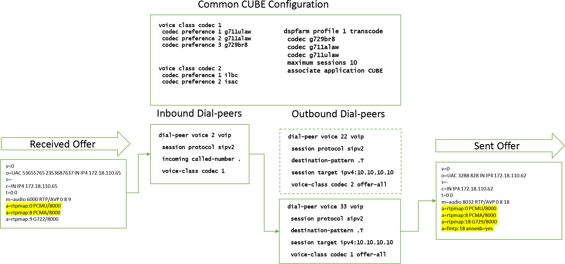
Figure 9-39 Incoming Offer and Dial Peer Filtering with an LTI Transcoder and Voice Class Codec
The rest of the configuration in this example is the same as the configuration we just examined. The ingress offer contains g711ulaw, g711alaw, and g722.
The following process occurs in Figure 8-39:
Step 1. Dial Peer 2 is used as the inbound dial peer because it has an applicable inbound match statement and a voice class codec with codecs applicable in the original offer.
Step 2. Outbound dial peers are examined, and a matching Dial Peer 33 is selected because Dial Peer 22 does not contain a common audio codec.
Step 3. Without the offer-all keyword, CUBE would simply offer g711ulaw and g711alaw, and the same behavior shown in Figure 9-38 would occur. Because offer-all is present and a CUBE LTI transcoder is configured, g729br8 can also be offered. If this codec is selected in the responding answer, the LTI transcoder can be invoked to perform interworking between the g729br8 outbound call leg and the inbound call leg. If g711ulaw or g711alaw is in the answer, no LTI transcoder is required due to the matching audio codec on the two call legs.
Codec Transparent and SDP Passthrough
The previous few sections describe how CUBE can be configured to exert control with codec selection and perform interworking in the event of mismatches. This section explores two ways CUBE can allow the endpoints to perform the negotiation. The first of the two methods is to use the command codec transparent on VoIP dial peers. When this command is added to a dial peer, CUBE does not perform any of the local filtering that influences audio codec selection that has been discussed up to this point.
Tip
Only supported audio codecs are eligible for transparent negotiation, and those that a dial peer does not normally support are filtered regularly.
Figure 9-40 illustrates codec transparent operations in CUBE. In this example, CUBE interworks an offer and an answer on both the inbound and outbound call legs.

Figure 9-40 Visualization of Codec Transparent Operations on CUBE
The following process occurs in Figure 9-40:
Step 1. The dial peers are configured with the codec transparent command. For this example, Dial Peer 1 is both the inbound dial peer and the outbound dial peer.
Step 2. An offer is received with g711ulaw, g711alaw, and g722.
Step 3. The offer also contains a custom SDP attribute.
Step 4. With codec transparent involved, CUBE passes the audio codecs through in the offer sent to the other call leg.
Step 5. CUBE drops (filters out) any custom SDP parameter and any non-supported CUBE audio codecs.
Step 6. The answer is passed through, with minimal interworking by CUBE.
Step 7. Because CUBE is involved in the media stream, the IP address and port of CUBE replace the remote endpoint’s IP address and port for the answer and offer.
In contrast, the command voice-class sip pass-thru content sdp can be added to a dial peer or globally to voice service voip and sip-subsection with pass-thru content sdp to pass all SDP parameters through CUBE untouched. This includes proprietary SDP attributes and audio codecs that are not normally supported by dial peers. CUBE still replaces media IP addresses and ports with its own IP address and RTP port if flow-through is configured, but the rest of the SDP is replicated from the inbound call leg to the outbound call leg. This is a very good method for passing SDP attributes that CUBE would otherwise filter from the inbound call leg to the outbound call leg.
Note
Many CUBE features do not work when SDP passthrough is configured. Consult the CUBE Configuration Guide, at https://www.cisco.com/c/en/us/td/docs/ios-xml/ios/voice/cube/configuration/cube-book.html, for all features that have restrictions with voice-class sip pass-thru content sdp and pass-thru content sdp.
Figure 9-41 illustrates codec pass-thru content sdp operations in CUBE. In this example, CUBE interworks an offer and an answer on both the inbound and outbound call legs.
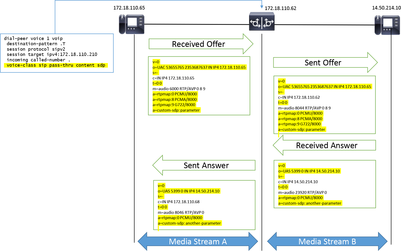
Figure 9-41 Visualization of Pass-through Content SDP on CUBE
The following process occurs in Figure 9-41:
Step 1. CUBE is configured with the pass-thru content sdp command.
Step 2. An offer is received with g711ulaw, g711alaw, and g722.
Step 3. The offer also contains a custom SDP attribute.
Step 4. With codec pass-thru content sdp, CUBE passes all SDP through from the inbound call leg to the other call leg, including the audio codecs and the custom SDP attribute.
Step 5. The answer to the offer that CUBE receives is passed through in full, including any additional custom SDP attributes.
Step 6. CUBE is still involved in the media stream, and CUBE’s IP address and port replace the remote endpoint’s IP address and port for the answer and offer.
Video Interworking and Suppression
Although most calls through CUBE are audio-only calls, CUBE does support video session negotiation in concert with audio. You can configure CUBE’s SIP dial peers to support h261, h263, h263+, h264, or mpeg4 by configuring the video codec command, as shown in Example 9-40. The default payload type for h263+ is 118, and for h264 it is 119. You can also see the configuration for these static payload types by using the rtp payload-type command.
Example 9-40 Video RTP Payload Configuration
dial-peer voice 1 voip
 video codec h264
 session protocol sipv2
 rtp payload-type cisco-codec-video-h264 117
 rtp payload-type cisco-codec-video-h263+ 118
Note
Unified CM and some video-enabled endpoints use payload type 97 or 126 for h264 video. Payload type 126 is not used by any dial peer configuration and can be freely assigned. Unfortunately, 97 is normally used by cisco fax-ack. If you were to attempt to change CUBE’s RTP payload type for h264 to 97, an error would appear, stating “ERROR: value 97 in use!” You must first change cisco fax-ack to an unused value and then change h264 payload type, as shown here:
rtp payload-type cisco-codec-fax-ack 111
rtp payload-type cisco-codec-video-h264 97
Because most video payload types are in the dynamic range (96 to 127), video payload negotiations are often asymmetric, meaning that one session participant sends media with payload type A, and the other session participant sends media with payload type B. When these scenarios occur, it is best to use the asymmetric payload command, which allows CUBE to interwork asymmetric payloads. Example 9-41 show how to enable this command globally or on a per–dial peer basis. Either dynamic-codecs or full can be used to enable this feature for video.
Example 9-41 Dynamic Payload Interworking on CUBE
!
voice service voip
 sip
  asymmetric payload {dtmf  | dynamic-codecs | full}
!
dial-peer voice 1 voip
 session protocol sipv2
 voice-class sip asymmetric payload {dtmf  | dynamic-codecs | full}
!
Tip
For some video interworking scenarios, it might be best to use SDP passthrough, discussed in the previous section, to replicate all video SDP from the inbound call leg to the outbound call leg with minimal modification by CUBE.
As indicated earlier, most sessions on CUBE are audio only. Oftentimes service providers and other equipment do not support video services. Even the act of advertising video in an SDP offer can cause calls to fail. As a result, CUBE has a command to perform audio+video to audio-only interworking between inbound and outbound call legs. Example 9-42 shows how to use the audio forced command globally or on a per–dial peer basis to remove all SDP m= lines except m=audio and m=image (fax) from an SDP offer generated by CUBE. The call leg that offered video receives an answer with the m=video port set to 0, indicating that video has been disabled. This command can also be leveraged to drop m=application lines on CUBE.
Example 9-42 Video Suppression on CUBE
!
voice service voip
 sip
  audio forced
!
dial-peer voice 1 voip
 session protocol sipv2
 voice-class sip audio forced
!
Media Flow-Through Versus Media Flow-Around
At the media plane, CUBE operates in two distinct ways:
• Media flow-through: With this configuration, CUBE is involved with the media path, and packets are sent to CUBE, which performs a Layer 2/3 header rewrite and optional codec manipulation via an LTI transcoder before retransmitting the media packet to the next-hop destination. This is the default behavior of CUBE via the command media flow-through configured under voice service voip.
• Media flow-around: With this configuration, CUBE advertises the remote endpoint’s media information as the source and destination. As a result, CUBE is no longer involved in the media flow post-call establishment. This can be configured with the command media flow-around in voice service voip. This is different from codec transparent and SDP passthrough, discussed previously, because CUBE still influences media negotiation as per codec filtering, as discussed up to this point; the main difference is that the IP address and port are those of the remote endpoint and not those of CUBE.
Figure 9-42 illustrates these two operational modes. In the media flow-through illustration, a SIP session is established between the IP phone, Unified CM, CUBE, and the service provider. When the call connects, the media path is between the IP phone, CUBE, and the service provider. The IP phone sends and receives RTP packets to/from CUBE as per the SDP offer/answer, and so does the ITSP. As a result, both parties send and receive packets with CUBE in the middle of the media stream.

Figure 9-42 CUBE Media Flow-Through Versus Flow-Around
In contrast, the media flow-around illustration shows the same devices involved in the call setup. The main difference is that CUBE does not advertise itself as a source or destination for media in the SDP offer/answer on either call leg. This results in the IP phone and ITSP now sending and receiving media. Before enabling media flow-around, you must confirm that the ITSP has valid IP routing to the IP phone’s network and that the IP phone’s network has valid routing to the ITSP. Any routing issues may lead to one-way or no-way audio situations. In addition, you willingly give up the ability for CUBE to perform transcoding and transrating because CUBE is no longer involved in the session’s media.
Figure 9-43 further illustrates how media flow-around affects SDP:
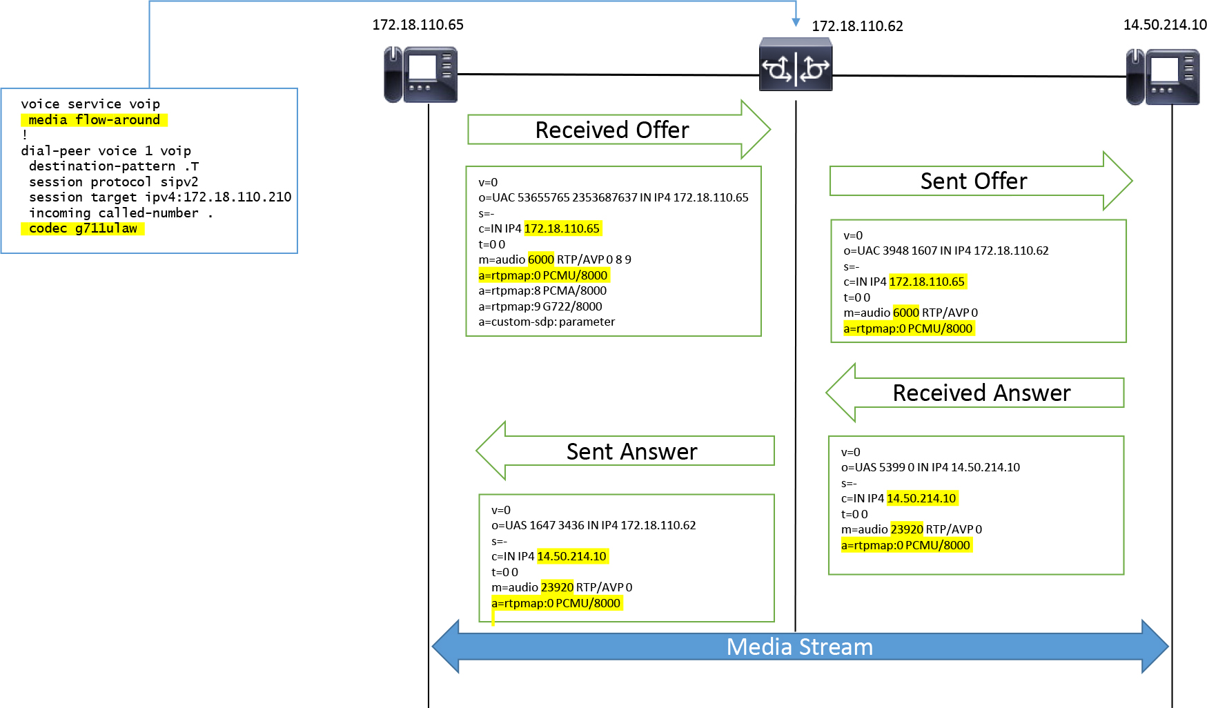
Figure 9-43 Offer/Answer with Flow-Around
Step 1. CUBE is configured with commands media flow-around and codec g711ulaw on the dial peers.
Step 2. An offer is received with g711ulaw, g711alaw, and g722.
Step 3. The offer also contains a custom SDP attribute.
Step 4. Due to the media flow-around command, CUBE advertises the remote endpoint’s IP address and port rather than an IP address and port on CUBE.
Step 5. CUBE still performs codec filtering, and due to the codec g711ulaw command, only g711ulaw is advertised.
Step 6. The custom SDP parameter and any non-supported CUBE audio codecs are dropped.
Step 7. The remote endpoint’s IP address and port contained in the answer to the offer generated by CUBE are used in the answer sent by CUBE rather than an IP address and port from CUBE.
Tip
media flow-around and pass-thru content sdp can be leveraged to ensure that CUBE does not perform codec filtering for a call that does not traverse CUBE at the media plane. In this situation, all SDP information, including IP address and port, are passed through CUBE with no modification.
Music on Hold
This chapter has already briefly discussed the concept of MOH and how it applies within the context of hold events. The hold music is an audio file played to a holdee from a MOH server for the duration of a hold event. Without MOH, the holdee would experience silence, or dead air, for the duration of the hold event. Many consider complete silence undesirable from the perspective of user experience, and therefore MOH is a widely deployed feature.
The audio file for MOH can be anything an administrator or an organization desires, from simple beeps or a music file to live radio or informational announcements, such as prerecorded sales information, stock prices, or even the current weather forecast. This information is delivered over the unicast audio stream opened up in the hold event discussed earlier in this chapter.
There are two methods for streaming MOH over a network from the MOH server to the holdee: unicast MOH and multicast MOH.
Unicast MOH is not too different from audio for a regular call. The main difference is that a normal call has bidirectional audio, while with unicast MOH, audio/RTP flows in one direction: from the unicast MOH source to the SBC and from the SBC to the upstream devices and ultimately to the holdee.
Previous sections in this chapter depict unicast MOH establishment between CUBE and Unified CM. First, the call is established with bidirectional audio. Then Unified CM makes the established audio stream inactive. Unified CM then renegotiates media and inserts the IP address and codecs of the unicast MOH server. (Figure 9-11 details how an SBC negotiates the same information on the other call leg or consumes the mid-call signaling.) After the hold and unicast MOH negotiation is complete, the RTP packets received from the unicast MOH server are forwarded to the next hop and all other upstream devices.
The implementation of multicast MOH is slightly more complicated than its unicast counterpart. The SIP signaling for the call establishment, hold, and multicast MOH negotiation follows the same sequence as for a unicast MOH session, but the semantics of how SDP is encoded in the offer/answer and the way MOH is served up by the network differ.
Note
If Unified CM is involved, the Cisco-proprietary SDP media attribute a=X-cisco-media:mmoh is present rather than a=X-cisco-media:umoh.
Tip
A device advertising a multicast address in SDP always sends a=recvonly in SDP, as per RFC 3264. The answer to this offer should always mirror the answer; for example, the answer may contain media direction attributes that are the same as those of the offer (a=recvonly).
The complexity of multicast MOH mainly derives from the underlying requirements of multicast. The first is that CUBE and the LAN/WAN must be properly configured for IP multicast capabilities in order to route multicast traffic properly. In addition, CUBE may be required join the multicast group specified in the SDP of the hold event and receive multicast RTP packets. The MOH server may also join this multicast group and will send multicast RTP, which is then replicated to all participants of the multicast session.
The second item is the inability of devices over the service provider network to join multicast groups scoped within an enterprise. Thus, CUBE must be able to convert the received multicast RTP into unicast RTP for transmission to the service provider network. CUBE requires only a few configuration lines to enable multicast-to-unicast conversion. These commands are detailed in Example 9-43. Figure 9-44 illustrates CUBE receiving multicast RTP packets from a multicast MOH audio source and then converting them into unicast RTP packets to be sent for transport over the ITSP network.
Example 9-43 Multicast MOH–to–Unicast MOH Conversion Commands
!
ip multicast-routing distributed
!
ccm-manager music-on-hold
!
interface GigabitEthernet0/0/0.249
 ip pim sparse-dense-mode
!
Tip
Underlying LAN and network infrastructure configuration to facilitate Multicast PIM on Layer 3 devices and IGMP multicast for Layer 2 devices are not covered in this book. In addition, the type of PIM configured on the CUBE interfaced is dependent on the type of LAN multicast implementation.
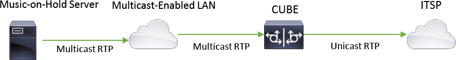
Figure 9-44 Multicast MOH–to–Unicast MOH Conversion on CUBE
Troubleshooting unicast MOH or multicast MOH issues always starts with verifying the signaling involved in setting up the unicast MOH or multicast MOH session by running debug ccsip messages and debug ccm-manager music-on-hold all. In addition, you can use show commands such as show call active voice compact and show voip rtp connections, which display RTP connections between CUBE and the MOH server or multicast IP address specified in the SIP signaling. Both IOS and IOS XE use the command show ccm-manager music-on-hold, which displays MOH packets replicated from the ingress call leg to the egress call leg. IOS XE can use the command show platform hardware qfp active feature sbc mmoh global, which shows multicast MOH packets received and passed to the ccm-manager application. Finally, using a packet capture (PCAP) is a great way to determine whether packets are being received from a MOH server or multicast IP address on the ingress CUBE interface.
Tip
With IOS XE, an IP PIM command must be defined on both the ingress and egress Layer 3 interface, or the multicast MOH–to–unicast MOH conversion will not occur. Without an IP PIM command on the egress interface, the output of show ccm-manager music-on-hold displays 0 packets received, and the output of show platform hardware qfp active statistics drop shows the multicast MOH RTP packets dropped with the reason “UnconfiguredIpv4Fia".
Tip
When integrating Unified CM with an IOS XE CUBE, the CallManager service parameter Duplex Media Streaming should be set to True. With this setting enabled, Unified CM advertises a valid MOH RTP port to CUBE rather than the dummy RTP port 4000. This is required for IOS XE source port validation checks, which drop the MOH RTP stream when port 4000 is used.
DTMF Interworking
The ability to press a button on a device to signal an input that is seamlessly transmitted across many different dispersed networks and delivered to a system that analyzes the input to perform actions with the call is one of the most important aspects of almost every session established in modern networks. These input signals take the form of dual-tone multifrequency (DTMF) and, as noted in Chapter 3, “VoIP Protocols: RTP, RTCP, and DTMF Relay,” can be conveyed in many different ways. Due to the number of DTMF signaling mechanisms, CUBE must have the ability to perform two forms of DTMF interworking:
• Interwork signaling to ensure proper negotiation of DTMF on the inbound and outbound call legs of a session: If CUBE does not properly perform an offer/answer with DTMF, there may be no DTMF at all for a given session.
• Interwork differing DTMF types when a DTMF mismatch occurs to ensure the proper replay and transmission of a received digit from one DTMF type to another: If CUBE fails to interwork DTMF from one call leg to another, the system waiting for user input may receive inputs in a format unknown to that device, which results in nothing happening when a user presses keys.
The first of these interworking scenarios starts with the administrator’s configuration. DTMF can be defined on a VoIP dial peer as shown in Example 9-44. The dtmf-relay command allows an administrator to create an ordered list of DTMF preferences on a dial peer. The question mark (?) command can be used to view all the supported DTMF types. A dial peer with no DTMF relay configuration assumes the default DTMF relay configuration, which is raw in-band audio. As discussed in Chapter 3, this can be problematic when using compressed audio codecs. Therefore, most Unified CM deployments use RTP-NTE, which follows the RFC 2833 and RFC 4733 standards for DTMF. When interworking calls with Unified CM, SIP-KPML can be leveraged as an out-of-band (OOB) DTMF solution.
![]()
Example 9-44 Dial Peer DTMF Relay Configuration Example
sj-cube(config)# dial-peer voice 1000 voip
sj-cube(config-dial-peer)# session protocol sipv2
sj-cube(config-dial-peer)# dtmf-relay ?
  cisco-rtp          Cisco Proprietary RTP
  h245-alphanumeric  DTMF Relay via H245 Alphanumeric IE
  h245-signal        DTMF Relay via H245 Signal IE
  rtp-nte            RTP Named Telephone Event RFC 2833
  sip-kpml           DTMF Relay via KPML over SIP SUBCRIBE/NOTIFY
  sip-notify         DTMF Relay via SIP NOTIFY messages
sj-cube(config-dial-peer)# dtmf-relay rtp-nte sip-kpml sip-notify
sj-cube(config-dial-peer)# do show run | section dial-peer voice 1000
dial-peer voice 1000 voip
 session protocol sipv2
dtmf-relay rtp-nte sip-kpml sip-notify
When configuring or troubleshooting DTMF relay, you should work to confirm the DTMF capabilities of all endpoints that will send calls through CUBE. If possible, a common DTMF relay type should be used so that CUBE can receive DTMF of the common type and replicate it to the other call leg with minimal effort. However, for instance when different DTMF relay types must be configured or negotiated, Table 9-6 provides a good starting point for the types of built-in DTMF relay interworking options CUBE supports for SIP-to-SIP calls. To view DTMF negotiation, debug ccsip messages should be used to verify the offer/answer for DTMF negotiation. The command debug voip rtp session name-event does not work reliably in IOS XE due to the change in architecture, so you should use a PCAP to view RTP-NTE DTMF.
Table 9-6 SIP DTMF Relay Interworking Matrix
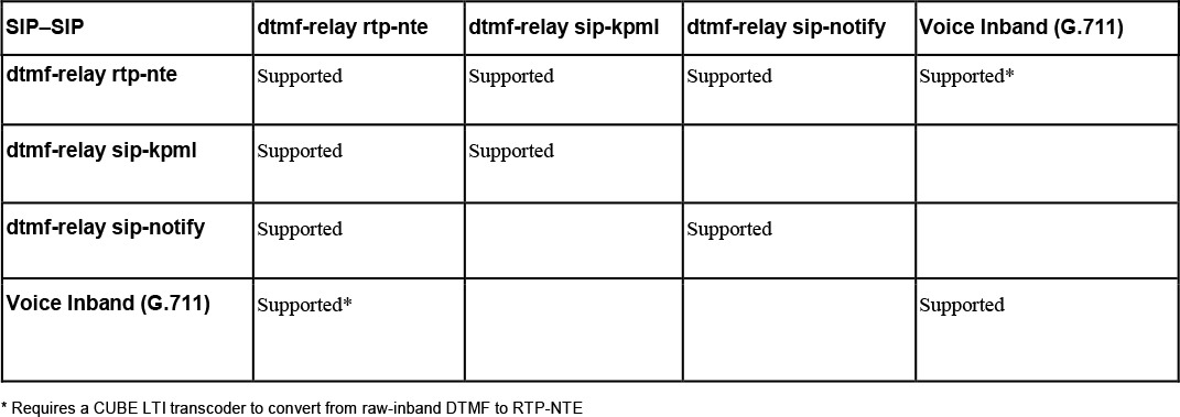
Tip
SIP-INFO has been omitted from Table 9-6. CUBE supports only SIP-INFO to RTP-NTE conversion and does not support the opposite.
Because RTP-NTE DTMF utilizes a dynamic payload type, there is a possibility of asymmetric payload types. In essence, one party sends RTP-NTE DTMF with one payload type while receiving another payload type for RTP-NTE DTMF. The command asymmetric payload dtmf can be used when asymmetric DTMF interworking is required. If both video and DTMF are asymmetric, you can use the command asymmetric payload full to enable the full suite of asymmetric payload interworking on CUBE.
When H.323 is used in conjunction with SIP call legs, DTMF can only be interworked in the ways illustrated in Table 9-7.
Table 9-7 H323-SIP DTMF Relay Interworking Matrix
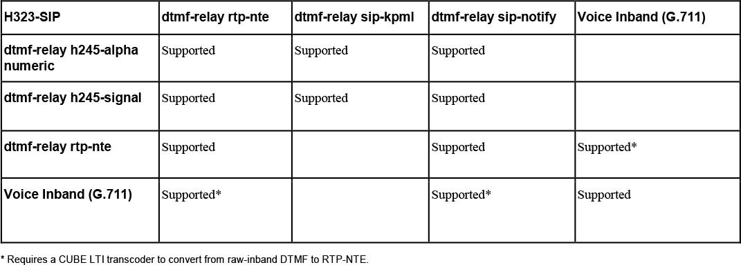
Troubleshooting CUBE Media
When troubleshooting media issues with CUBE, you should always work to verify that the session establishment messages are negotiating the correct media parameters in addition to the inbound and outbound dial peers being selected, since the dial peers can exert control over the audio and video codec negotiation. You can use debugging commands such as debug ccsip messages and debug voip ccapi inout to look at the SDP offer/answer on the inbound and outbound SIP call legs through CUBE, and you can use CCAPI debugging to see the actual dial peers being selected.
If troubleshooting an active call, you can use show commands such as show call active voice compact, show call active voice brief, and show voip rtp connections to view the media information negotiated by the signaling in real time. In IOS XE, the command media bulk-stats should be enabled under voice service voip for sent (TX) and received (RX) RTP packet statistics in the show call active voice brief command. This command is disabled by default in IOS XE due to the possibility of adversely affecting processing performance by counting every RTP packet sent and received by CUBE when there are many calls. You should examine the output of the show commands to confirm that there are no more than 100 active calls before using media bulk-stats.
Embedded packet captures (PCAPs) can be leveraged by IOS XE CUBE to gather packets that are sent and received by physical interfaces. Packet captures can provide a precise look into exactly what is on the network. Packet captures can also be used to play back the RTP and confirm whether a given network segment is introducing any issues into the RTP stream. You can use packet captures at the source and destination to verify that packet loss, jitter, and delay fall within the acceptable g114 standards:
![]()
• One-way packet loss less than 1%
• One-way delay less than 150 ms
• One-way jitter less than 100 ms
There are several additional factors you can examine when troubleshooting media issues with CUBE. Media issues on the network come in many shapes and sizes. When troubleshooting CUBE media issues, attempt to answer the following questions with debug and show commands and with packet captures:
• Is the issue intermittent or reproducible on demand? Intermittent issues may require a more in-depth analysis to find the exact cause of the issue, while issues that are easily reproducible tend to be easier to troubleshoot because samples can be provided on demand. For example, for no-way or one-way audio issues that are reproducible on demand, you only need to establish an active call and then use debug and show commands to quickly determine where the audio is being lost. On the other hand, for an intermittent one-way or no-way audio situation, you might need to enable Switched Port Analyzer (SPAN) at various points in the network and send the results to a local collection server along with applicable debugging collected via syslog for a more granular analysis. Typically you need more than one sample of an intermittent audio issue in order to find a trend in the data.
• What is the exact symptom of the audio quality or media issue? Properly defining the audio quality symptom in the beginning of a troubleshooting effort will guide your troubleshooting efforts greatly. For example, choppy audio might be due to packet loss on a given network segment, and your troubleshooting for this issue would be different from troubleshooting for one-way audio or no-way audio, which might indicate improper packet routing, dial peer binding, or even access control list (ACL)/firewall permission issues. Understanding the exact symptoms of an audio quality issue will help reduce your troubleshooting efforts.
• Is media flowing through CUBE or around CUBE? If CUBE is not involved in the media flow, the media troubleshooting needs to be done on the transit network and the endpoints.
• Which devices are involved in the call? You can use debug and show commands to gain a proper understanding of the devices involved in the media path. The IP address and port information negotiated during a session can be used to filter packet captures, check permission rules, and check packet routing. Similarly, you should verify that the correct IP address for CUBE is being advertised to the remote endpoint. A global or dial peer binding misconfiguration can cause an incorrect IP address to be presented. (See Chapter 8 for more information.)
• Which media codec is being negotiated, and is this the correct one? A quick verification that the desired media codecs are being negotiated is very beneficial to understanding the media issue. For example, if g711ulaw is being negotiated rather than g729 and the LAN has not been properly optimized, there may be a potential for oversubscribed links, leading to packet loss.
• Are there any media resources being allocated? LTI or SCCP media resources may be invoked by CUBE or Unified CM to perform media interworking. The inclusion of these devices changes how packets route through the network and adds another variable to the equation. You should work to verify whether media resources are involved and whether they are the correct media resources for the job. Invoking media resources from another geographic region can lead to RTP packets taking a different network path, which may not be optimized for voice traffic. If possible, work to eliminate variables by removing the media resource from the media path and checking to see if the issue remains.
• Is quality of service (QoS) being leveraged, and are RTP packets being marked and queued accordingly? RTP packets should be marked with the Differentiated Services Code Point (DSCP) value Expedited Forwarding (EF) so that QoS and policing policies on the network can treat them with priority. The lack of markings or an incorrect QoS strategy could lead to the mishandling of RTP packets and various audio quality issues.
• What is the bandwidth of the interfaces being used? The type of links and the bandwidth of the links should be examined in conjunction with the total traffic expected. Oversaturation can lead to a variety of audio quality issues. Refer to the following site for more information on VoIP call bandwidth calculation: https://www.cisco.com/c/en/us/support/docs/voice/voice-quality/7934-bwidth-consume.html.
• Are there any access control lists (ACLs) on the interfaces that are used for media? The IP addresses and ports for RTP media should be allowed through ACLs to avoid being dropped on the ingress or egress of an interface. For example, if you see packets in a packet capture but do not see packets incrementing in show call active voice brief, you need to examine the interface for errors. You can also use show platform hardware qfp active statistics drop to see the ACL drop reason increasing the packets per second for the active session with media issues.
• Are there any local zone-based firewalls (ZBFWs) or other firewalls in the media path? Similarly, incorrect zone pairings or firewalls that have not allowed the proper media IP addresses and ports can cause audio issues. With a ZBFW, you can examine the ingress and egress zone pairing to ensure that packets are allowed via the command show zone-pair security source inbound-zone destination outbound-zone. You can also use show platform hardware qfp active statistics drop to verify why the number of packets per second is increasing for the active session with media issues.
• Is IP routing on CUBE configured to send the packet out the correct interface toward the remote destination, as instructed by the signaling? For no-way and one-way audio issues, you should examine the packet routing to verify that packets are being sent to the remote destination negotiated by the signaling. This includes verifying both the next-hop IP address for Layer 3 routing and the egress interface. You can use commands such as show ip route a.b.c.d and show ip cef a.b.c.d, where a.b.c.d is the remote IP address toward which CUBE has been instructed to send packets. For the reverse direction, ensure that the media binding, if configured, is correct. Incorrect media binding configurations can cause CUBE to advertise the incorrect IP to a remote device, which in turn results in the remote device sending packets to an IP that is not routable from their local subnet. Refer to Chapter 8 for more information about both application signaling and media binds on CUBE.
There is not a one-size-fits-all approach to troubleshooting media issues. The topic alone could fill an entire Cisco Press book. This information presented in this chapter is by no means exhaustive but does provide a good starting point for any media issue. With a bit of diligent troubleshooting and by systematically working through the aforementioned questions, you should be able to narrow the scope of an issue significantly.
Other CUBE Features
CUBE has many other features that you can use for interworking and interoperability for session establishment at both the signaling and media planes—for example, CUBE high availability, CUBE security with TLS/SRTP, CUBE call admission control, CUBE call recording through dial peers, and XMF Unified CM API services. These topics are not included in the CLACCM 300-815 certification blueprint, so they are not included in this book. For a fully comprehensive list of features, see the Cisco CUBE Configuration Guide, at https://www.cisco.com/c/en/us/td/docs/ios-xml/ios/voice/cube/configuration/cube-book.html.
References
Inamdar, Kaustubh, Steve Holl, Gonzalo Salgueiro, Kyzer Davis, and Chidambaram Arunachalam. Understanding Session Border Controllers: Comprehensive Guide to Designing, Deploying, Troubleshooting, and Maintaining Cisco Unified Border Element (CUBE) Solutions. Hoboken: Cisco Press, 2018.
“Cisco Unified Border Element Configuration Guide,” https://www.cisco.com/c/en/us/td/docs/ios-xml/ios/voice/cube/configuration/cube-book.html
“Voice Over IP - Per Call Bandwidth Consumption,” https://www.cisco.com/c/en/us/support/docs/voice/voice-quality/7934-bwidth-consume.html
RFC 2069, “An Extension to HTTP : Digest Access Authentication,” https://tools.ietf.org/html/rfc2069
RFC 2617, “HTTP Authentication: Basic and Digest Access Authentication,” https://tools.ietf.org/html/rfc2617
RFC 2833, “RTP Payload for DTMF Digits, Telephony Tones and Telephony Signals,” https://tools.ietf.org/html/rfc2833
RFC 3261, “SIP: Session Initiation Protocol,” https://tools.ietf.org/html/rfc3261
RFC 3262, “Reliability of Provisional Responses in the Session Initiation Protocol (SIP),” https://tools.ietf.org/html/rfc3262
RFC 3264, “An Offer/Answer Model with the Session Description Protocol (SDP),” https://tools.ietf.org/html/rfc3264
RFC 3311, “The Session Initiation Protocol (SIP) UPDATE Method,” https://tools.ietf.org/html/rfc3311
RFC 3515, “The Session Initiation Protocol (SIP) Refer Method,” https://tools.ietf.org/html/rfc3515
RFC 3551, “RTP Profile for Audio and Video Conferences with Minimal Control,” https://tools.ietf.org/html/rfc3551
RFC 3892, “The Session Initiation Protocol (SIP) Referred-By Mechanism,” https://tools.ietf.org/html/rfc3892
RFC 4028, “Session Timers in the Session Initiation Protocol (SIP),” https://tools.ietf.org/html/rfc4028
RFC 4733, “RTP Payload for DTMF Digits, Telephony Tones, and Telephony Signals,” https://tools.ietf.org/html/rfc4733
RFC 7587, “RTP Payload Format for the Opus Speech and Audio Codec,” https://tools.ietf.org/html/rfc7587
Exam Preparation Tasks
As mentioned in the section “How to Use This Book” in the Introduction, you have a couple of choices for exam preparation: the exercises here, Chapter 11, “Final Preparation,” and the exam simulation questions in the Pearson Test Prep software online.
Review All Key Topics
Review the most important topics in the chapter, noted with the key topics icon in the outer margin of the page. Table 9-8 lists these key topics and the page number on which each is found.
![]()
Table 9-8 Key Topics for Chapter 9
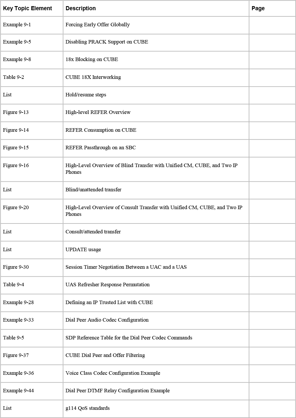
Complete Tables and Lists from Memory
Print a copy of Appendix C, “Memory Tables” (found on the companion website), or at least the section for this chapter and complete the tables and lists from memory. Appendix D, “Memory Tables Answer Key” (also on the companion website), includes completed tables and lists to check your work.
Define Key Terms
Define the following key terms from this chapter and check your answers in the glossary: