Chapter 6. Unified CM Call Control Features
This chapter covers the following topics:
• Media Resources: This section introduces the concept of media resources that are used for Music on Hold, conferencing, and media termination points and the configuration constructs that control access to media resources in Unified CM.
• Ad Hoc and Meet-Me Conferencing: This section describes several Unified CM features that allow for users to establish and join ad hoc and Meet-Me multi-party audio or video conferences.
• Music on Hold (MOH): This section discusses the configuration of the Music on Hold feature.
• Media Resource Groups and Media Resource Group Lists: This section details the configuration and function of Media Resource Groups (MRGs) and Media Resource Group Lists (MRGLs).
• Call Park: This section describes the call park feature and the various options available to customize the configuration.
• Call Pickup: This section discusses the various call pickup features, how they work, and how to configure them.
• Regions and Codec Preferences: This section helps you understand how Unified CM selects audio and video codecs to use when establishing a call between two parties.
• Call Admission Control (CAC): This section explains how to implement location-based (including enhanced location-based) call admission control to ensure that connections with limited bandwidth are not overrun by too many calls. This section also discusses the options to reroute calls through the PSTN in the event of a CAC failure.
This chapter covers the following CLACCM 300-815 exam topics:
• 1.1 Troubleshoot these elements of a SIP conversation
• 1.1.c Mid-call signaling (hold/resume, call transfer, conferencing)
• 1.3 Troubleshoot media establishment
• 5.1 Troubleshoot Call Admission Control (exclude RSVP)
• 5.6 Configure supplementary functions
• 5.6.a Call park
• 5.6.b Meet-me
• 5.6.c Call pick-up
Cisco Unified Communications Manager provides a variety of features that enhance your ability to manage and route calls in the system, including multi-party conferencing, call park, and call pickup. It also includes features for managing the use of bandwidth for calls through the ability to select appropriate codecs, depending on the endpoints involved and the amount of bandwidth between them. In addition, it allows you to restrict the number of calls to a site if an additional call will cause congestion on the network. This chapter looks at each of these capabilities in detail.
“Do I Know This Already?” Quiz
The “Do I Know This Already?” quiz allows you to assess whether you should read the entire chapter. If you miss no more than one of these self-assessment questions, you might want to move ahead to the “Exam Preparation Tasks” section of the chapter. Table 6-1 lists the major headings in this chapter and the “Do I Know This Already?” quiz questions related to the material in each of those sections to help you assess your knowledge of these specific areas. The answers to the “Do I Know This Already?” quiz appear in Appendix A, “Answers to the ‘Do I Know This Already?’ Quiz Questions.”
Table 6-1 “Do I Know This Already?” Foundation Topics Section-to-Question Mapping
1. Which types of media resources are provided by IOS devices? (Choose three.)
a. Media termination point (MTP)
b. Transcoder
c. Conference bridge
d. Interactive voice response (IVR)
e. Music on Hold (MOH)
2. Which protocols do media resources use to communicate with Unified CM? (Choose three.)
a. DSP Registration Protocol (DRP)
b. Skinny Client Control Protocol (SCCP)
c. Session Initiation Protocol (SIP)
d. Hypertext Transfer Protocol (HTTP)
e. Media Gateway Control Protocol (MGCP)
3. Which codecs are supported by the IP Voice Media Streaming App service for ad hoc conferencing? (Choose two.)
a. G.711
b. G.722
c. G.729
d. Opus
e. Wideband 256k
4. When configuring Cisco Meeting Server as an ad hoc conference resource for Unified CM, intro which trust store must you import the Cisco Meeting Server SSL certificate?
a. CallManager
b. CallManager-trust
c. Tomcat
d. Tomcat-Trust
e. IPsec
5. What types of conferences are natively available in Unified CM? (Choose three.)
a. Cisco Webex
b. Cisco Conductor
c. Ad hoc
d. Meet-Me
e. Conference Now
6. Where is most configuration for the Conference Now feature performed?
a. Conference bridge media resource configuration
b. End-user configuration
c. Device configuration
d. Annunciator configuration
e. Interactive voice response configuration
7. Which of the following are types of audio sources that can be configured on a device? (Choose two.)
a. Device hold source
b. User hold source
c. Line hold source
d. Network hold source
e. Global hold source
8. How many file-based audio sources can be configured on a single Unified CM cluster?
a. 1
b. 50
c. 51
d. 500
e. 501
9. Which of the following describes the behavior when a media resource group list is configured both on a phone device and on the device pool of which the phone is a member?
a. The media resource groups from the two lists are combined, with preference for the group’s part of the list that is configured on the phone.
b. The media resource groups from the two lists are combined, with preference for the group’s part of the list configured on the device pool.
c. Only the media resource group list on the device is used.
d. Only the media resource group list on the device pool is used.
e. This is an invalid configuration that would generate an error.
10. What is the default duration for the Call Park Reversion timer?
a. 15 seconds
b. 30 seconds
c. 60 seconds
d. 120 seconds
e. 1800 seconds
11. If a user uses the directed call park feature to park a call at park destination 3001 and another user dials 3001 to retrieve the call, will the call be retrieved successfully?
a. It depends on the calling search space of the phone attempting to retrieve the call.
b. No; the call cannot be retrieved by directly dialing the number.
c. Yes; this will work if the number is dialed from the phone that originally parked the call.
d. Yes; this will work if the user has speed dial configured for extension 3001.
e. Yes; this will work from any phone registered to the same Unified CM cluster.
12. Which of the following call pickup features are available in Unified CM? (Choose three.)
a. Forward pickup
b. Group pickup
c. Alternate pickup
d. Other pickup
e. Directed pickup
13. Which of the following is true of an audio codec preference list?
a. It allows an administrator to add or remove codecs advertised by Unified CM.
b. It allows an administrator to select the order in which codecs are advertised by Unified CM.
c. It allows an administrator to disallow specific codecs from being used when calls are being recorded.
d. It defines the amount of audio bandwidth available between two devices.
e. It defines the amount of total session bandwidth (both audio and video) allowed between two devices.
14. For what types of calls can you set bit rate limits by using the regions feature? (Choose three.)
a. Audio
b. Video
c. Presentation sharing
d. Desktop sharing
e. Immersive video
15. Which of the following must be configured for enhanced location call admission control to work between devices in two locations? (Choose three.)
a. LBM groups
b. Locations
c. Links
d. Weights
e. Regions
16. Which locations are preconfigured on Unified CM? (Choose three.)
a. Location 0
b. Hub_None
c. Phantom
d. Shadow
e. Transparent
Foundation Topics
Media Resources
A number of Unified CM features cannot be discussed without first discussing the broader topic of media resources. The annunciator, conferencing, transcoding, Music on Hold, and media termination point features all rely on some kind of media resource because these features all require Unified CM to terminate media on a device other than the originating or terminating endpoint. This chapter explores each of these features and details each media resource. Media resources fall into the following categories:
• Conferencing: These resources facilitate multi-party audio or video communications by mixing the audio and video streams of participants. A conference involves, at a minimum, three participants. The upper bound restricting how many participants are involved in a single conference is usually governed by the application hosting the conference resource.
• Interactive voice response (IVR): Interactive voice response (IVR) resources play prompts and can interactively collect dual-tone multifrequency (DTMF) digits and take action based on user input. Two features that leverage the IVR functionality are the Conference Now feature and the Mobile Voice Access (MVA) feature.
• Annunciator: The annunciator capability is invoked by Unified CM any time a prerecorded message needs to be played to a user, such as a message saying “Your call cannot be completed as dialed” when the user calls an invalid number. Annunciators can also be used for other purposes, such as playing a ringback during a call transfer.
• Music on Hold (MOH): MOH resources play one of several audio streams when callers are placed on hold. The audio stream presented to a user may be a series of tone-on-hold beeps, static music, a custom prerecorded announcement, or even live audio sourced from a third-party device.
• Media termination point (MTP): An MTP acts as an intermediary to terminate media between two devices and is used for a variety of reasons. For example, an MTP might be used as a trusted relay point (TRP) or as a way to terminate media on behalf of another device when that device is not able to terminate media for itself in a given situation. MTPs can also be used to interwork DTMF from one type to another type in scenarios where there is a DTMF mismatch between two endpoints.
• Transcoding: Transcoding resources use digital signal processors (DSPs) to convert one audio codec to another for scenarios where two devices cannot support a common codec. The most common example is interworking a codec such as G.711μ-law into a variant of G.729. Transcoders can also perform transrating—that is, changing the packetization rate—where required. A transcoder could be inserted to interwork the same media stream with differing ptime values. An example would be interworking G.711μ-law media stream with a ptime of 20 ms into a G.711μ-law media stream with a ptime of 30 ms (and vice versa).
In general, a media resource is made available to Unified CM either through a Skinny Client Control Protocol (SCCP) registration or, for some conference resources, a combination of Session Initiation Protocol (SIP) and HTTP connectivity. This chapter explores both connectivity models and the configuration required to make them work.
![]()
Media resources can be provided by hardware devices or software. The IP Voice Media Streaming App service can be activated on one or more servers in a Unified CM cluster to provide several different software-based media resources. Smaller deployments can have this service activated on the same servers as Unified CM, while larger clusters typically have dedicated servers to run this service. The IP Voice Media Streaming App service handles playing music on hold, plays messages through the annunciator, handles the IVR for the Conference Now feature, serves as an audio mixer for audio conference calls, and provides software media termination point (MTP) resources. All these capabilities are configured from the Media Resources menu in the Unified CM Administration user interface.
In addition to the media resources provided by the IP Voice Media Streaming App service, a variety of hardware and software solutions can register to Unified CM and provide conference resources as well. This chapter discusses them, as well as the individual types of media resources.
Ad Hoc and Meet-Me Conferencing
While the most basic function of Unified CM is to connect two parties in a point-to-point call, in today’s highly collaborative world, there is increasing need to communicate between three or more people simultaneously. A significant portion of multi-party conferencing occurs on cloud-based meeting platforms such as Cisco Webex or on-premises solutions such as Cisco Meeting Server (CMS). However, there are situations in which a simple ad hoc conference is needed, without the overhead associated with scheduling a meeting and asking participants to dial in. To meet this need, Unified CM offers a variety of options to enable ad hoc conferencing invoked directly from a phone or soft client. Leveraging the same infrastructure used for ad hoc conferencing, Unified CM also provides the ability for very basic Meet-Me conferencing functionality when the advanced functionality of a dedicated meeting platform is not needed. In order to enable these features, you must first add conference resources to a Unified CM cluster.
Unified CM supports various types of conference resources. The types differ in their ability to support audio or video, the number of simultaneous streams supported, the maximum number of participants in a conference, and the codecs supported. Unified CM supports a variety of legacy platforms as media resources, but this chapter discusses the ones that are recommended for new deployments. (The legacy platforms are configured in nearly the same way as the ones we discuss in this chapter.) These conference resources are discussed in this chapter:
![]()
• Unified CM software-based conference resources (IP Voice Media Streaming App service)
• Cisco IOS-based hardware conference resources
• Cisco Meeting Server (CMS)
Once you have activated the IP Voice Media Streaming App service, all the media resources provided by the service, including conferencing resources, register because they are preconfigured any time you add a server to a cluster. While the default configuration will give you basic functionality, you might want to make some changes to the default configuration.
To view and change the configuration of the conference resources, navigate to Unified CM Administration > Media Resources > Conference Bridge and click the Find button. You should see conference bridges named CFB_ followed by a number for each server in your cluster. If the IP Voice Media Streaming service is activated and started, you see the resources registered for that server in the cluster. Note that although the service runs on one or more servers in the cluster, the service registers to the Cisco CallManager service based on the configured device pool on the device, just like a phone. This means that the media resource might not be registered to the same server that the IP Voice Media Streaming App service is running.
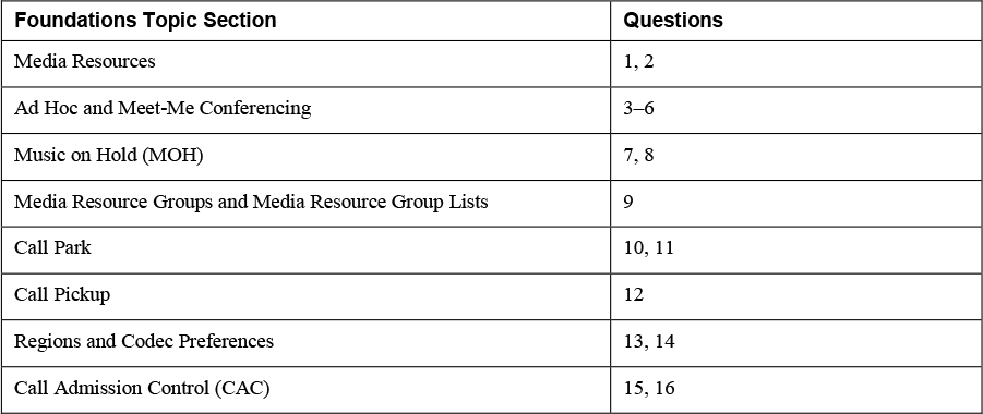
Figure 6-1 shows an example of a Unified CM cluster with two servers with the IP Voice Media Streaming App service running and registered. If you have already configured other types of conference bridge resources, you might see other items on the list as well, but by default, you always see the software conference resources for each node in your cluster.
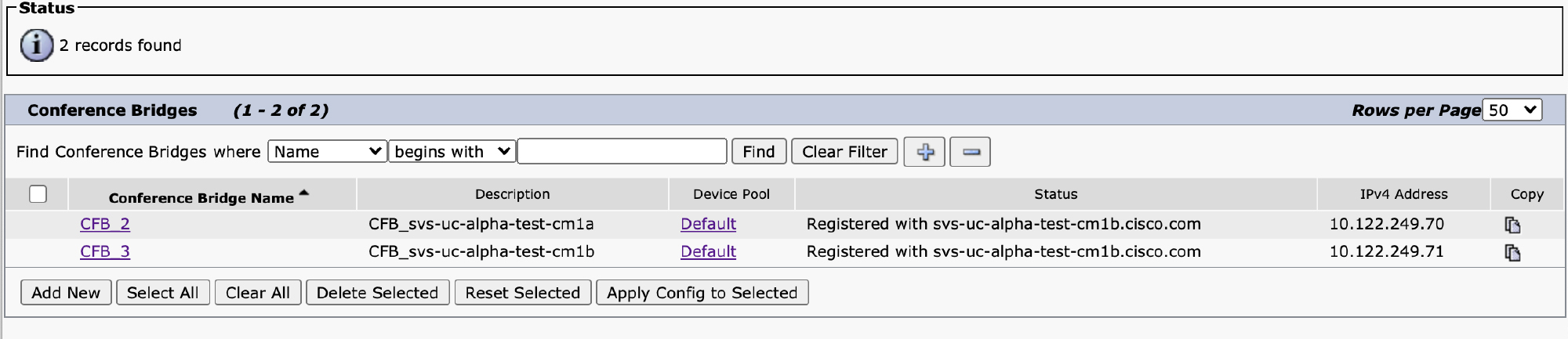
Figure 6-1 List of Software Conference Resources in Unified CM Administration
To make a configuration change to the conference bridge resources, select the resource from the list. You then see options shown in Figure 6-2.

Figure 6-2 Software Conference Bridge Resource Configuration
![]()
There are not many configuration parameters here. You can change the name to be more descriptive, perhaps to indicate which server in the cluster it belongs to. The name is not important, but note that changing the name causes the resource to re-register, so you should not do this while calls are actively using the resource. The device pool determines the Unified CM group that this resource uses to register, so basically it determines which servers in the cluster the resource registers to. Unified CM can use resources registered to any server in the cluster, even those registered to a server that is different from the server where a phone is trying to invoke a conference resource. It is best practice to distribute conference resources across your cluster in the same way you distribute phones across multiple servers in the cluster. The device pool also indicates the region where the conference resource is located. This is used to select the appropriate codec. Note that the IP Voice Media Streaming App conference resource supports only the G.711 and Wideband 256k codecs, so you need to ensure that your regions are configured such that they permit these codecs to the resource or you have an appropriate transcoding resource available.
The Location field is used for location-based call admission control, which is discussed later in this chapter. This setting determines whether there is enough bandwidth available between and endpoint and this conference resource. If there is not enough bandwidth, Unified CM attempts to allocate a different resource.
The Use Trusted Relay Point setting determines whether calls that invoke this conference resource must connect media through a trusted relay point (TRP) instead of sending media directly to the conference resource. The setting Default for this parameter means to use the configuration from the common device configuration, if one is configured. Most of the settings in the common device configuration do not apply to conference resources, so they are not used.
As you can see, there are very few parameters required to register a conference resource; however, when we discuss how media resource groups and media resource group lists can be used to control access to media resources, you will see that there are a variety of service parameters that apply to conference resources as a whole.
Note
The software conference implementation is very basic. It works well enough for small three- to four-party conference calls, but it can be problematic for larger calls because it does not intelligently identify silent parties, and as more participants are added, the overall volume level for all participants can be affected. It is highly recommended to use either a Cisco IOS hardware conference resource or Cisco Meeting Server as a conference resource.
To enable a Cisco Integrated Services Router (ISR) device equipped with DSPs as a conference resource, you must add it to Unified CM and then configure the router as a conference resource. To configure it in Unified CM, add a new conference bridge resource and select Cisco IOS Enhanced Conference Bridge as the conference bridge type. The configuration is nearly identical to the software conference bridge resource configuration shown in Figure 6-2. However, in this case, the name is important. The name you select as the conference bridge name must match the name you configure in IOS. Also, these types of media resources support encryption, so you have the option to select whether the device security mode is encrypted or not.
Once you have configured the resource in Unified CM, you must then configure the router to register as a media resource. Example 6-1 shows the commands needed to configure and register an IOS enhanced conference bridge resource.
![]()
Example 6-1 IOS Enhanced Conference Bridge Configuration
ISR-4451-X# show inventory
[..truncated..]
NAME: “PVDM subslot 0/4", DESCR: “PVDM4-64 Voice DSP Module"
PID: PVDM4-64          , VID: V01  , SN: FOCXXXXXXXXXX

ISR-4451-X# show run | section sccp|voice-card|dspfarm
!
sccp local GigabitEthernet0/0/0
sccp
sccp ccm 10.122.249.70 identifier 1 version 7.0
sccp ccm 10.122.249.71 identifier 2 version 7.0
!
voice-card 0/4
 dsp services dspfarm
!
dspfarm profile 1 conference
 codec g729br8
 codec g729r8
 codec g729abr8
 codec g729ar8
 codec g711alaw
 codec g711ulaw
 codec g722-64
 codec ilbc
 maximum sessions 4
 associate application SCCP
 no shutdown
!
sccp ccm group 1
 bind interface GigabitEthernet0/0/0
 associate ccm 1 priority 1
 associate ccm 2 priority 2
 associate profile 1 register svs-ios-conf01
!
These resources all use SCCP to register to Unified CM, so you need to enable SCCP and bind it to a local interface IP address on the router with the commands sccp and sccp local <interface>, as shown in Example 6-1. You must then add the IP addresses of the Unified CM servers to which you would like this resource to register. Note that you should ensure that this matches the Unified CM group in the device pool associated with the resource as configured in Unified CM. Note that you should select Version 7.0 for any Unified CM Version 7.0 or later (which should be all deployments).
Next, you enable the Packet Voice Digital Signal Processor Module (PVDM) on the system for use as a dspfarm by applying the command dsp services dspfarm to the applicable voice card. In Example 6-1, voice-card 0/4 references the motherboard DSP on an ISR 4000 Series router. The actual location of your voice card may be different, depending on the model of your ISR. Issue the show inventory command to locate the slot/sublot of the PVDM module. Example 6-1 shows the relationship between the show inventory command and the voice-card command.
Once a module has been enabled for use as a dspfarm, the next task is to create a dspfarm profile for the conference resource. You can specify one or more codecs that you would like the conference resource to support, and you can also indicate the maximum number of sessions to support and associate the profile with the SCCP application. The maximum sessions are determined by the number of DSP resources that you have available and configured on the router for DSP farm purposes. You can issue the command maximum sessions ? to see an on-demand total for the available maximum number of configurable sessions. Finally, you should enable the dspfarm profile by using the command no shutdown. One key item to remember is that the default maximum participants in an IOS conference bridge is 8. You can increase this number by running the maximum conference-participants command with an upper limit of 32 participants in a given conference session. The trade-off for increasing the maximum participants in a single conference session is that the maximum number of conference sessions available shrinks. Example 6-1 allows for four conference sessions with eight participants each.
Finally, you create an sccp ccm group to bind the group to an interface on the router and then associates the previously configured servers with the dspfarm profile. The dspfarm profile number must match the one previously configured. Similarly, the profile name configured here should also match what was configured in Unified CM. Once you have taken these steps, the resource should appear as being registered in Unified CM administration.
One large drawback of IOS-based conferencing is that it supports only audio conferencing. A second drawback is the total number of participants that can be engaged in audio-only conferences using IOS dspfarms as a conference resource. If you want your ad hoc and Meet-Me conferences to support video calls, the best choice is to leverage the Cisco Meeting Server (CMS) platform. CMS is also a very scalable audio conferencing platform as well, with the ability to scale to hundreds of participants in a single meeting. CMS conference resources use a combination of SIP and HTTPS to set up conference calls. Unified CM uses HTTPS signaling to dynamically create a new conference as needed and then directs calls into that conference by using SIP. Because of the dual nature of the signaling required, you will see that the configuration requires the configuration of both.
Before you can configure CMS as a conference resource, you must first create a SIP trunk from Unified CM to the CMS server or servers. For details on how to configure a SIP trunk, refer to Chapter 5, “Unified CM SIP Trunk Configuration.” After you have created the SIP trunk, you can add a new conference resource from the Unified CM Administration > Media Resources > Conference Bridge by adding a new device and selecting the type of CMS server.
Figure 6-3 shows the configuration of a CMS server as a conference bridge resource.

Figure 6-3 Cisco Meeting Server as a Conference Resource in Unified CM
The name specified is arbitrary and just for your information. You must also select the SIP trunk you created that points to the CMS server or servers. By default, Unified CM assumes that the IP addresses configured on the SIP trunk are the same ones that should be used for the HTTPS signaling. If you want to override this, select the Override SIP Trunk Destination as HTTPS Address checkbox, and then you can add one or more IP addresses to use for the HTTPS signaling.
In the HTTPS Interface Info section, you must specify a username and password that you have configured on the CMS server that has API access. Also ensure that the HTTPS port matches your CMS server (which is typically port 8443).
![]()
Note
Unified CM always uses an encrypted HTTPS connection to communicate with CMS; therefore, Unified CM must properly trust the certificate presented by CMS when connecting. Unified CM must have certificates for all the CMS cluster servers present in the CallManager trust store. This is important!
The final parameter that we have not discussed is the Conference Bridge Prefix parameter. When Unified CM creates a dynamic conference for an ad hoc call, it picks a long random number for the call. You can choose to prefix that number with a set of digits you configure in the Conference Bridge Prefix parameter to ensure that conferences created by this cluster never overlap with other parts of your dial plan or other Unified CM clusters. This is useful when you have more than one cluster configured to use the same CMS cluster for ad hoc conferencing. Just make sure you specify a unique prefix for each cluster.
Once you have added CMS as a conference resource, Unified CM can use it when a user invokes an ad hoc or Meet-Me conference from a phone. As before, the device pool determines the region configuration for calls to this media resource, but in this case, it is the region of the SIP trunk that matters.
A variety of service parameters allow you to customize conference-related features at a global level. If you navigate to Unified CM Administration > System > Service Parameters and select the Cisco CallManager service, you see a section named Clusterwide Parameters (Feature - Conference). Figure 6-4 shows the options available on this page.

Figure 6-4 Conference Configuration Parameters in Unified CM
Table 6-2 describes the important parameters in this section. Several parameters are omitted from this table because they are not important to the discussion in this chapter.
![]()
Table 6-2 Conference Configuration Parameter Details


Once you have configured ad hoc conference resources on a cluster, you can invoke an ad hoc conference in a variety of ways, depending on the endpoint you are using. On IP phones, while on a call, you press the Conference button or soft key, call a third participant, and then press the Conference button or softkey again to create the conference. At that point, Unified CM selects a conference resource based on the capabilities of the participants and connects the three parties to the conference resource. You can also use the Join feature to join active calls together into an ad hoc conference. Similarly, in Cisco Jabber or Cisco Webex Teams, you use the Merge button to merge two existing calls into a conference. Regardless of how you invoke the feature, in the end, you have three or more participants in a call. You can then continue to add additional participants, one at a time. If at any point the number of participants drops to two, the conference resource is de-allocated, and the remaining two parties are connected directly to each other, thereby freeing up your conference resource.
Later in this chapter, you will see how media resource groups and media resource group lists can be used to determine which conference resources are used. By default, all configured resources are in a default group, which is reachable by all devices configured on the cluster, so even with no media resource groups configured, ad hoc conferencing works.
Meet-Me conferencing uses the same media resources configured for ad hoc conferencing but allows users to dial in to a meeting number instead of requiring a user to add each person to the conference. There is also a newer feature that is similar to Meet-Me called Conference Now, which enhances the original Meet-Me feature. What makes a Meet-Me conference unique is that it must be initiated from a phone by using the Meet-Me softkey or button. By default, most phones do not display the Meet-Me button or softkey, so it must be added to either the softkey template for the phone or added as feature button on the display of the phone where you want to enable Meet-Me. You must also designate phone numbers as Meet-Me conference numbers. You can configure Meet-Me numbers from the Unified CM Administration > Call Routing > Meet-Me Number/Pattern configuration menu. Figure 6-5 shows the configuration of a Meet-Me number range.

Figure 6-5 Meet-Me Pattern Configuration
A Meet-Me conference can be configured as either a single directory number or a pattern, as shown in Figure 6-5. In this example, the numbers 80010000 through 80010009 are available for Meet-Me conferences. Once a Meet-Me number has been configured, it is available to anyone whose calling search space allows them to reach the pattern, based on the partition in which you have placed the Meet-Me pattern. If you want these numbers to be reachable from the PSTN, you must ensure that the appropriate call routing is in place so that calls from the PSTN can reach these directory numbers, just as you would for any other phone line.
![]()
Once the Meet-Me pattern is configured and conference resources are available, a user initiates a Meet-Me conference by pressing the Meet-Me button or softkey and then dialing an available Meet-Me number. This feature is relatively primitive, and there is no way to schedule or check to see if someone else is using a given Meet-Me number. However, if a user presses the Meet-Me softkey and dials a number that is already being used for a Meet-Me call, the user hears a reorder tone.
Once a user has activated a Meet-Me conference using the Meet-Me softkey, other users can dial in to the meeting by simply dialing the phone number. They must do this without pressing the Meet-Me softkey. If someone dials the Meet-Me number before someone has used the Meet-Me key to start the meeting, callers simply get a reorder tone. Once a conference is started, it remains active until all participants have left the conference. When the conference has ended, the number is once again available for someone to initiate a Meet-Me conference using the Meet-Me softkey.
![]()
Unified CM Version 11 added a new feature that is an extension of this feature to make it more scalable and easier to use called the Conference Now feature. Conference Now requires that the host and meeting participants dial in to a single phone number, which is answered by an IVR system. The IVR system prompts the user for a meeting ID and a PIN. A Conference Now meeting must be started by a meeting host before participants can talk to each other; attendees who join before the meeting host joins hear hold music instead getting a reorder tone, as with the Meet-Me feature.
Enabling Conference Now is a multistep process. The first step is to ensure that there are conference media resources available. You must also have an IVR resource available. IVR resources can be provided by the IP Voice Media Streaming App service discussed earlier in this chapter, so if the service has been activated and started, it should be available. You can verify that the IVR is available by navigating to Unified CM Administration > Media Resources > Interactive Voice Response (IVR). Figure 6-6 shows an example in which two IVR resources are registered.
Figure 6-6 IVR Resources Registered in Unified CM Administration
As with the other media resources we have discussed, you can configure the device pool on these resources to control which Unified CM they register to, and you can also control the region for codec selection. IVR supports G.711, G.729, and Wideband 256k codecs.
![]()
Note
One important note about IVR is that it only supports out-of-band (OOB) DTMF relay. In other words, it does not support in-band DTMF, such as RFC 2833/4733 (RTP-NTE). This means that if you have a device dialing in that supports only in-band DTMF, a media termination point (MTP) is needed to convert from in-band to out-of-band DTMF. For more information about DTMF, review Chapter 3, “RTP, RTCP, and DTMF Relay.”
When you have conference and IVR media resources registered, there are several steps needed to configure the Conference Now feature. This feature is strongly tied to individual end users, so most of the configuration is actually performed on the end-user configuration, but the first step is to configure the directory number for the Conference Now IVR resource. This is done by navigating to Unified CM Administration > Call Routing > Conference Now. Figure 6-7 shows the configuration parameters for Conference Now.

Figure 6-7 Conference Now IVR Configuration
The first parameters you must configure are the directory number and partition for the number that users will dial to join a conference. You can make this number a DID so that it is reachable from the PSTN as well as by internal users. The only two other parameters are Maximum Wait Time for Host Unit Participant Is Disconnected, which specifies how long a participant can be placed on hold while waiting for the host to join, and MOH Source While Participant Is Waiting. These parameters are all global. You can only have a single IVR number, and all participants must hear the same MOH source while on hold. If for some reason you would like multiple PSTN numbers to be able to reach the IVR resource (for example, if you have gateways in several countries and you want to provide international numbers to dial in), you can use translation patterns to translate any number of phone numbers to the IVR number and thereby provide multiple dial-in numbers.
Once the IVR number is configured, the only remaining step is to enable end users for the Conference Now feature. The Conference Now feature relies on two pieces of configuration that are not specific to the Conference Now feature: the user’s PIN and the primary extension. Both of these must be configured for the Conference Now feature to work and can be found by navigating to Unified CM Administration > User Management > End User. The primary extension will become the user’s meeting number, and the PIN will be required for the host to start the meeting. In addition to these parameters, there is some Conference Now–specific configuration as well. Figure 6-8 shows the Conference Now Information section of the end-user configuration page.

Figure 6-8 Conference Now Configuration on the End-User Page
To enable a user for the Conference Now feature, select the Enable End User to Host Conference Now checkbox. When the configuration is saved, the Meeting Number field populates with the primary extension for the user. You may optionally add an attendee access code, which will be required for attendees (not the host) to join the meeting. Even with the attendee access code, the meeting does not start until the host joins and enters their personal PIN.
When the Conference Now configuration is complete, the process of joining a Conference Now meeting is easy:
Step 1. Both attendees and the host dial the IVR directory number and are prompted for the meeting ID. The meeting ID is the primary extension of the user whose meeting they want to join.
Step 2. The IVR system prompts the user to enter the host PIN if the user is the host or just press the pound (#) key if the user is not the host.
Step 3. If the host enters the correct PIN, the meeting is started. If an attendee is joining and presses pound, that user might be prompted for the attendee access code, if one is configured.
Music on Hold (MOH)
Music on Hold (MOH) enables callers to hear music or announcements when they are placed on hold. It is also used for features such as Conference Now and call queuing (discussed in Chapter 4, “Unified CM Call Routing and Digit Manipulation”). As mentioned earlier, MOH is provided by the IP Voice Media Streaming App service. Up to this point, we have not discussed the scalability and capacity of this service. By default, the service provides up to 48 streams each for software conferencing, annunciator, IVR, and MTP. These settings are all configured in the service parameters for the IP Voice Media Streaming App service, which can be accessed by navigating to Unified CM Administration > System > Service Parameters > Server > Select IP Voice Media Streaming App. Figure 6-9 shows the parameters available on this page.
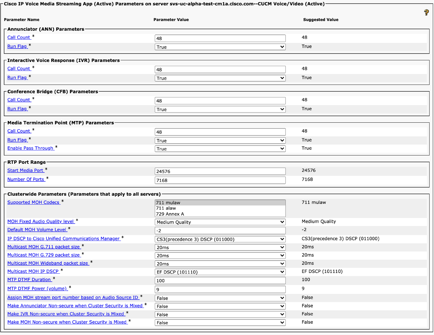
Figure 6-9 IP Voice Media Streaming App Service Parameters
You can see that the top half of the page lets you specify a run flag and call count for each media resource provided by the IP Voice Media Streaming App service, with the exception of MOH. However, the bottom of the page provides MOH-related configuration settings. The Run Flag allows you to disable a specific media resource if you do not want to use it. For example, if you are going to use hardware or external conference resources, you might want to disable the conference bridge capability.
![]()
The Supported MOH Codecs parameter allows you to specify which codecs the server should natively stream for MOH. By default, only G.711ulaw is supported. You can multi-select all four options (711 mulaw, 711 alaw, 729 Annex A, and Wideband) if you want to support all four. Note that the wideband option doesn’t appear unless you scroll down to see it.
So where do you configure the run flag and stream count for MOH? These settings are located on a separate configuration page dedicated to the configuration of the MOH resources. As with other media resources, the MOH server registers with Unified CM with by using SCCP and is configured by default when a server is added to the cluster. The Music on Hold service is configured from Unified CM Administration > Media Resources > Music On Hold Server. Figure 6-10 shows the configuration page for an MOH server.

Figure 6-10 Music on Hold Server Configuration
As with the other media resources, you can configure a device pool and location to indicate to the MOH server which server in the Unified CM cluster to register to and also control the region’s configuration. You can also specify a location for call admission control purposes. You can see that the equivalent of the Call Count setting available for other resources is available here, with the parameter Maximum Half Duplex Streams. By default, Unified CM supports 250 streams. The settings for MOH as well as the other services can be increased on servers that are dedicated to providing these services. (For guidance on the maximum number of streams supported for each platform, please consult the Unified CM documentation for MOH.) This configuration page also has a Run Flag setting, which allows you to disable MOH on a specific server, if you so desire.
The MOH service supports both unicast and multicast streams. For unicast, each participant on hold has a unique media stream from the MOH server to the party hearing the hold music; for multicast, the server only ever sends a single stream continuously, and then end devices are instructed to join the multicast group to hear the stream. Multicast MOH is far more scalable but requires the network to be multicast enabled between the MOH server and any client that may be placed on hold. The most common deployment model is unicast MOH.
![]()
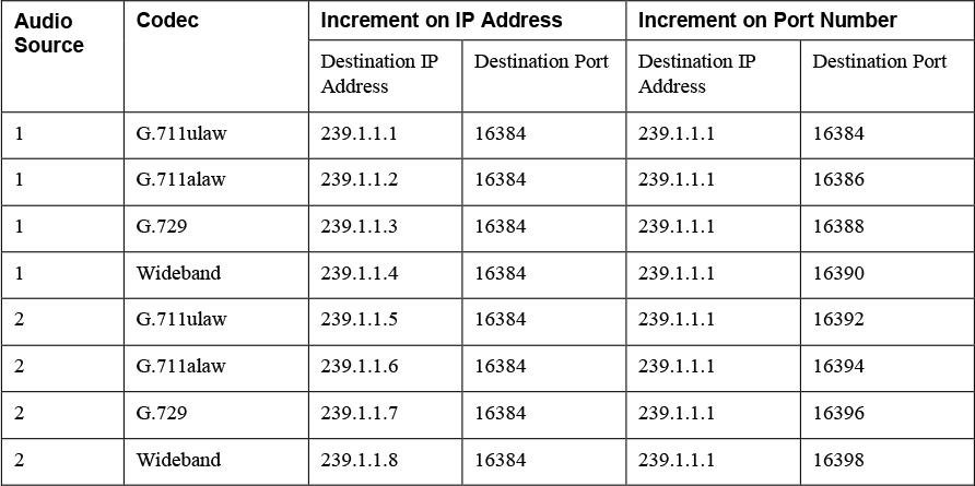
If deploying multicast MOH, you should understand how the base multicast address works. As we will discuss in a moment, you can have up to 501 MOH audio sources configured. Each audio source can have up to 4 codecs configured (depending on the setting in the service parameter discussed previously). If you set Increment Multi-cast On to IP Address, Unified CM starts with the Base Multi-cast IP Address value and increments the IP address for each source and codec, potentially using up to 2004 multicast IP addresses. If you chose to increment based on port number, the same IP address is used, and only the port number is incremented; however, you should use this option with caution because multicast networks either allow or deny traffic based on a multicast IP address, so any phone that gets placed on hold receives all the multicast MOH streams being sent to the multicast IP address, even if they are on different port numbers. Incrementing on IP address is the preferred method if you are going to use multicast. Table 6-3 shows the difference between incrementing by IP address and by port number when the base address is configured as 239.1.1.1 and the port number is configured as 16384 on a server with all four codecs enabled for MOH and two audio sources.
Table 6-3 Example of the Differences Between Incrementing Multicast on IP Address and Incrementing Multicast on Port Number
Once you have configured the MOH server, you can add audio sources. By default, Unified CM comes with a single audio source, named SampleAudioSource, which is assigned the source ID 1. Each MOH audio source is assigned a number from 1 through 501. Number 51 is special in that it is reserved for a fixed audio source; however, this source has not been usable since Unified CM moved to VMware, which does not have an easy way to connect USB devices to a virtual machine. When this source was available, a USB sound card could be used as an input to stream live audio from an external source. Streaming a live audio source today requires an external music streaming device that can be rebroadcast, as discussed shortly.
Note
SampleAudioSource is a recording of a song named Opus No. 1 written and recorded by high-school friends Tim Carleton and Darrick Deel long before IP phones existed. Some consider it to be the most played song ever and certainly the most known Music on Hold track. Various articles talk about the history of this song, and an episode of This American Life (Episode 516, January 17, 2014) goes into the history of the song.
To add a new audio source or modify an existing one, navigate to Unified CM Administration > Media Resources > Music On Hold Audio Source. Figure 6-11 shows the configuration page for a Music on Hold audio source.
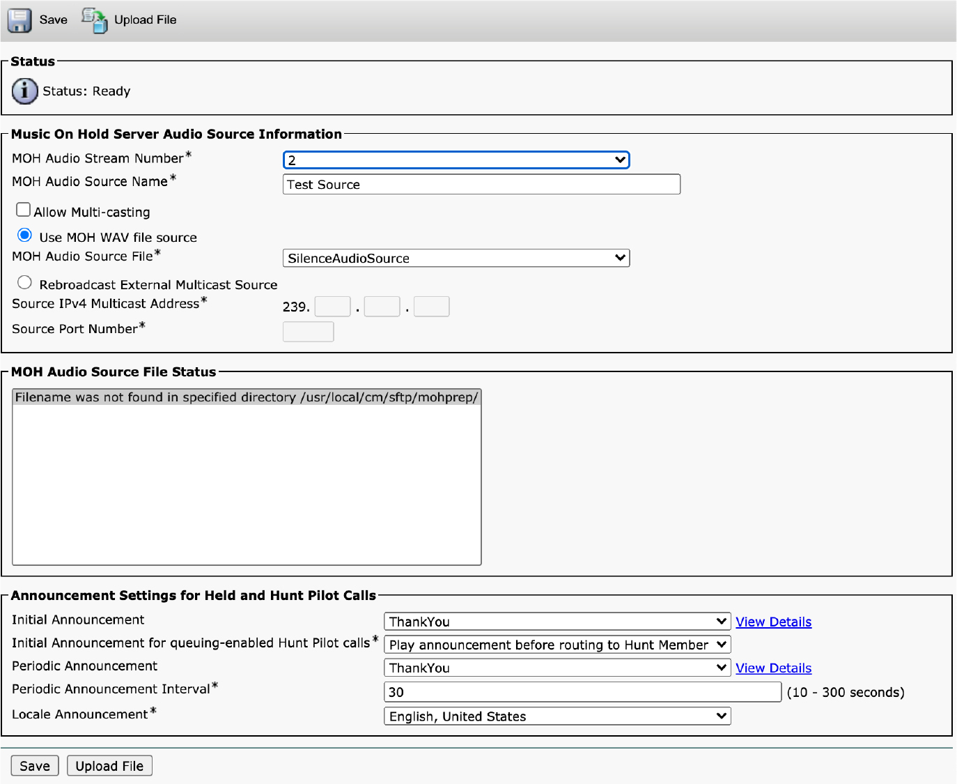
Figure 6-11 Music on Hold Audio Source Configuration
You must select an audio source ID from 1 to 501. You will notice that 51 is missing from the list because it is dedicated to the fixed source, as mentioned earlier. You use this source ID in various parts of the Unified CM configuration to select the audio source. On this page, you can either choose an audio file from one of the files already uploaded or you can upload one by clicking the Upload File button at the top or bottom of the page. You can also upload and manage uploaded files from the Unified CM Administration > Media Resources > MOH File Management menu. Instead of using a static file, you can choose to rebroadcast an external multicast source. The primary use case for this option is to use an external streaming device connected to a live audio source that is configured to stream to the network on a multicast IP address. Unified CM is then configured to listen to this multicast group as the source and rebroadcast that source as needed to unicast or multicast destinations, as it would stream any other prerecorded file. Figure 6-12 highlights how this works with Unified CM.
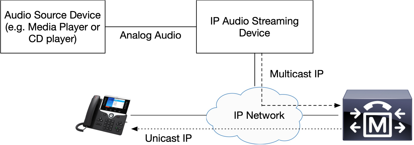
Figure 6-12 Music on Hold Multicast Rebroadcasting
Note
Cisco Unified Border Element (CUBE) can also perform multicast-to-unicast MOH interworking for calls involving service providers over public networks. This process is detailed in Chapter 9, “CUBE Interworking Features.”
The MOH audio source configuration also allows you to configure initial and periodic announcements that are played at the beginning and at regular intervals while a call is on hold. The option Initial Announcement for Queuing-Enabled Hunt Pilot Calls indicates whether the initial announcement is played even when the call is not going to be placed on hold because a member is available.
![]()
When your audio sources are configured, you can decide which sources are played when a user places a call on hold. You should understand two basic types of hold:
• User hold: With a user hold, a user presses the Hold button on a phone to explicitly place the caller on hold. If Phone A and Phone B are having a conversation, and the user of Phone B presses the Hold button, Phone B’s user hold source is streamed to Phone A.
• Network hold: A network hold occurs when a call is placed on hold as part of the processing of a supplementary service, such as park, transfer, or conference. If Phone B presses the Transfer button to transfer a call, Phone A still gets placed on hold but hears Phone B’s network audio source while the rest of the transfer operations complete.
The network and user audio sources can be configured in a variety of locations in the Unified CM Administration user interface. The various configuration options allow you to configure audio sources at various levels of granularity. The least-granular configuration is with a pair of service parameters found by navigating to Unified CM Administration > System > Service Parameters > Server > Cisco CallManager. In the Service section of the service parameters page are two parameters, Default Network Hold MOH Audio Source ID and Default User Hold MOH Audio Source ID, that each take an integer value from 1 to 501 to indicate the default audio source. If this value is not overridden on any of the more granular configuration options, this is the audio source callers hear.
The next place the audio sources can be configured is under the Common Device Configuration. You can find this by navigating to Unified CM Administration > Device > Device Settings > Common Device Configuration. This configuration page has options that allow you to select both the user and network MOH audio sources. You can then apply this common device configuration to groups of devices. If a phone has a common device configuration selected that has audio sources configured, they override the global service parameter.
You can also configure a specific user and network hold source on a device. Such settings override the global and/or common device configuration settings. The final location where the audio sources can be configured is on an individual line. The line setting overrides any of the other settings. This means that you can have different hold music played for calls to the same phone, depending on which line the call comes in on.
Note
Note that the audio source setting determines which file or rebroadcast a user hears, but it does not determine which MOH server plays the audio. The determination of which MOH server is used is determined by the configuration of the media resource group list associated with the held party.
Media Resource Groups and Media Resource Group Lists
Two configuration elements control access to media resources: media resource groups (MRGs) and media resource group lists (MRGLs). These work similarly to route groups and route lists, covered in Chapter 4. All media resources—MOH servers, annunciators, IVRs, conference resources, media termination points, and transcoders—can be placed into media resource groups.
![]()
By default, there are no media resource groups configured in Unified CM. Any media resource that is not in a media resource group is placed into what is known as the default group. There is no way to see this group or the devices that are in the default group other than by looking at SDL trace files, but if a media resource does not appear in any MRG, it is in the default group. This means that, by default, all devices registered to a cluster have access to all media resources because all media resources are in the default group by default. The moment a media resource is added to an MRG, it is removed from the default group, even if the group has not been assigned to a media resource group list.
Media resource groups are unordered lists of media resources, which means all resources in a group are considered equivalent. Generally speaking, Unified CM uses the resource in the MRG that has the most available resources. For example, if two MOH servers are available and both support 250 streams and one server has 1 call on hold, the next call that gets placed on hold uses the other server. Media resources within an MRG are distributed evenly. Figure 6-13 shows the configuration of an MRG that contains all the available media resources.

Figure 6-13 Media Resource Group Configuration
A media resource can appear in multiple media resource groups. One common practice is to add all media resources on a cluster to a media resource group named something like Catch All. This group is not assigned to any media resource group lists, but it ensures that no devices exist in the default group. This is done to reduce the potential for media resources from different geographical regions or sites being allocated from the default list. The last thing you want to do is have a call from North Carolina to San Jose using a media resource registered in Brussels, which could introduce delay, jitter, and other quality impairments to the media stream. Because media resources can appear in multiple groups, you can add these same resources to other groups, as needed to ensure they are being allocated properly.
Once you have assigned media resources to MRGs, you can add the MRGs to media resource group lists. MRGLs are ordered lists of MRGs. In other words, all resources in the highest MRG on the list are used before attempting to use the resource of a subsequent MRG. There are some exceptions to this rule, depending on the parameters set for conferencing, where audio resources may be prioritized over video resources if the number of video participants is below the configured threshold or if you have configured parameters to prefer encrypted audio over video calls. One other caveat to note is that Unified CM uses transcoders as media termination points (but cannot use media termination points as transcoders), so it is highly recommended to put transcoding resources in a separate MRG with a lower priority than software MTP resources so that you do not waste transcoding resources (which require expensive hardware DSPs) as MTPs unless absolutely necessary.
Once you have added MRGs to MRGLs, you must assign the MRGLs to devices. Just as with the MOH configuration, there are a variety of places where you can configure an MRGL. The least granular configuration is on the device pool. Each device pool has a setting for MRGLs that applies to all devices in the device pool. If you want to override this setting, you can do so on the device. Note that unlike with calling search spaces, when an MRGL is configured on a device, it overrides the device pool configuration; it does not add the two. This means that you could inadvertently remove media resources from a device when you add an MRGL if you are not careful to ensure that the MRGL configured has access to all the resources already available on the device pool MRGL.
![]()
When it comes to selecting a media resource, the MRGL used depends on the feature. For example, for MOH, the MRGL used is that of the held party as it is the device that is being connected to the media resource. In the case of conferencing, the MRGL used is that of the conference creator (that is, the user pressing the Conference softkey to start an ad hoc conference or the user starting a Meet-Me conference by pressing the Meet-Me softkey). In the case of annunciators and IVR resources, it is the MRGL of the user dialing in to the IVR system or the device where the announcement is being played. MTPs and transcoders are generally allocated based on the MRGL of the device needing the resource (for example, if a SIP trunk needs an MTP to support a feature such as early offer).
Call Park
The call park feature is similar to call hold in that it allows you to place a caller on hold temporarily and then resume the call at a later time. The difference is that call park allows you to resume the call on a different phone or line than the line that originally parked the call. This can be useful, for example, in environments where overhead paging systems are used to announce the presence of a call and anyone who hears the announcement can choose to retrieve the parked call.
When a call is parked, it is associated with a call park number that can be dialed from any phone that has access to the park pattern (via its calling search space) to retrieve the call. You must first configure the range of numbers that can be used for parking the call. This is done from Unified CM Administration > Call Routing > Call Park. Figure 6-14 shows the configuration for a call park range.
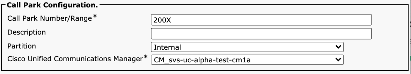
Figure 6-14 Call Park Configuration
A call park range can have up to two Xs in the pattern (for example, 20XX), so a park range can support up to 100 parked calls. If you need to be able to support more parked calls, you just need to add more park ranges. The partition is important because it determines which park range will be used to park the call as well as who can retrieve the calls parked in this range. In deployments that involve multiple sites, it is typical to have separate park ranges (in separate partitions) for each site since retrieving a parked call across sites is not a typical use case; however, if this is something that is important to your deployment, you can do so. In fact, parked calls can even be retrieved from a different cluster or even from the PSTN, as long as they have access to dial the park number based on the calling search space of the calling device.
![]()
The last parameter, Cisco Unified Communications Manager, is a bit unusual for a pattern like this. For this parameter, you select a server in the cluster to associate with this call park range. By default, you must configure non-overlapping call park ranges for each server in your Unified CM cluster where devices might need to park a call. If a phone is registered to a server in the cluster that does not have a call park range configured (that the phone can reach via its calling search space), the call park operation fails. This behavior can be modified, and there is a service parameter that controls the behavior. To change this parameter, navigate to Unified CM Administration > System > Service Parameters > Server > Cisco CallManager and click the Advanced button. If you change the setting for Enable Clusterwide CallPark Number/Ranges to True, the Cisco Unified Communications Manager setting on the call park range becomes irrelevant, and all configured park numbers can be used by devices registered to any server in the cluster. At some point in the future, this may become the default configuration, and the setting to tie the park range to a specific server will be removed.
While we are on the topic of service parameters, it helps to go through all the call park–related service parameters available (see Figure 6-15).
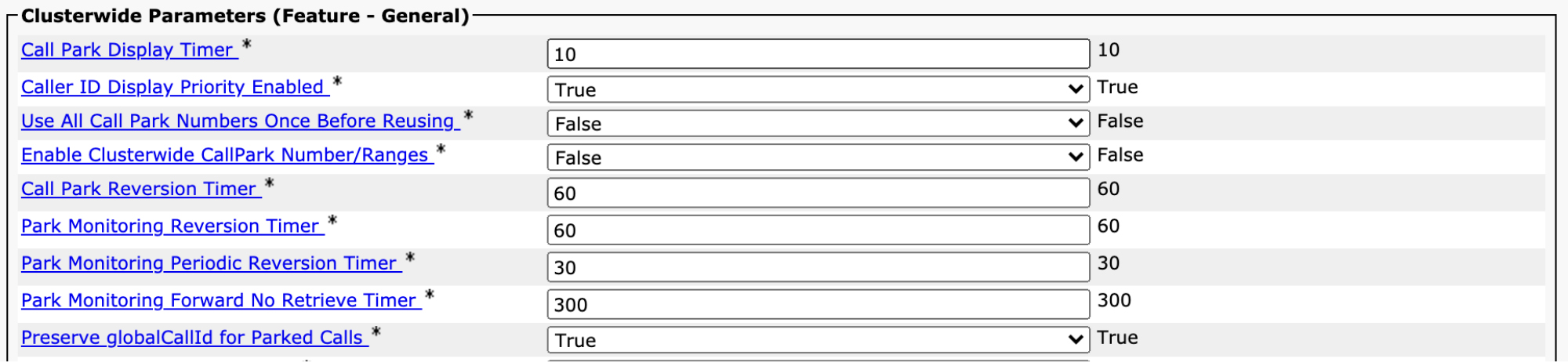
Figure 6-15 Call Park Service Parameters
Most of the parameters are timers that control how the call park feature works. To understand these timers, you must first understand some fundamentals of call park, such as how it works:
Step 1. A user parks a call by pressing the Call Park softkey or button on his or her phone.
Step 2. Unified CM automatically selects an available park number from the configured park ranges and displays a message on the phone indicating the number where the call is parked.
Step 3. The party that gets parked starts hearing hold music. The Music on Hold source selected is the network MOH source for the line that parked the call.
Step 4. Anyone with the correct calling search space that can reach the number range from where the call park number was selected can dial that number and retrieve the parked call. The service parameter Call Park Display Timer determines how long the message stays on the phone indicating the park number.
Once a call is parked, a timer is started. If no one picks up the parked call within the allotted time, a call park reversion occurs. The timer that governs this is called the Call Park Reversion timer, and it is set to 60 seconds by default. After this timer expires, the call rings the phone that parked the call, and the parked party stops hearing music on hold and hears ringback instead. Administrators can change this timer to extend the amount of time a call can remain parked. One challenge with call park reversion is that when the call reverts back to the party that parked the call, the call behaves like a new call coming into that phone. This means that if the phone is busy, the Call Forward Busy treatment is followed, and if the call is not answered, the Call Forward No Answer treatment is applied.
![]()
Some phones support an additional feature call park monitoring. This feature is generally available only on newer SIP phones with larger displays, such as the Cisco 8800 Series and 9900 Series phones. On phones that support park monitoring, the user has an enhanced experience when parking a call. Instead of just displaying the number where the call is parked for just a few seconds, the phone shows the call being parked until someone retrieves the parked call. At any point, the user who parked the call can just press one button to retrieve the parked call without having to dial the park number. Also, the phone continuously displays the number where the call is parked.
There are three parameters that affect the behavior of call park on phones that support park monitoring. The Park Monitoring Reversion timer behaves like the Call Park Reversion timer. After the Park Monitoring Reversion timer expires, the phone that parked the call rings, but the parked party continues to hear the hold music. The phone that parked the call at this point can choose to ignore the park reversion. From this point onward, at intervals dictated by the Park Monitoring Periodic Reversion timer, the phone that parked the call rings again until the call is retrieved from park. By default this is every 30 seconds. If no additional configuration is done, this goes on indefinitely. However, one additional timer can be enforced: the Park Monitoring Forward No Retrieve timer. This timer determines how long the call continues trying periodic reversion indications until a forwarding behavior is taken.
The park monitoring forwarding, when not retrieved, is determined by the configuration on each individual line. Figure 6-16 shows the park monitoring configuration on a directory number.

Figure 6-16 Park Monitoring Configuration on a Line
Note that although this configuration appears on all lines, it only applies to phones that support park monitoring. You can configure park monitoring forwarding on no retrieve to behave differently depending on whether the call that is parked is an internal call or an external call. External calls are any calls on devices that are marked as off-net devices. You can also configure the Park Monitoring Reversion timer for a line that overrides the global service parameter.
There is an additional variation of call parked called directed call park. Whereas standard call park allows Unified CM to select the park number automatically, directed call park allows a user to park a call at a specific phone number by transferring the call to a directed call park number. The user experience with directed call park is different. Instead of using the Park softkey or button, the user simply performs a standard call transfer as if transferring the call to another extension, but instead of dialing another extension, the user dials the directed call park number. The user needs to know the directed call park number beforehand.
![]()
The directed call park feature is usually deployed alongside a busy lamp field (BLF) for directed call park. When a BLF for directed call park is configured, a button appears on a phone that lights up any time a call is parked on that call park slot. This BLF can appear on many phones, and users who see a call parked on that slot can simply press the button to retrieve the parked call without having to call a number to retrieve the call. Directed call park behaves slightly differently than standard call park in that a prefix is needed to retrieve the parked call. The best way to understand this is to look at the configuration for a directed call park number. To configure a directed call park number, navigate to Unified CM Administration > Call Routing > Directed Call Park. Figure 6-17 shows the configuration options for a directed call park number in the first box. The second box shows the configuration of a directed call park BLF added to an IP phone’s second button; this is accomplished by navigating to Unified CM Administration > Device > Phone. If the phone button template does not contain a BLF Directed Call Park button, the parameter Add a New BLF Directed Call Park is part of the Unassigned Associated Items section of the line association configuration. You can use the Modify Button Items button at the top of the line association section to add the BLF directed call park option to the phone button of choice and then select Add a New BLF Directed Call Park to associate the call park number to the button.

Figure 6-17 Directed Call Park Number Configuration
The first major difference between the configuration for directed call park and standard call park is that the directed call park configuration requires a specific number to be configured. It cannot be a range specified using a wildcard; each directed call park number must be configured individually. As with any other pattern, you must select a partition to place the number in and ensure that it is reachable from any calling search space that needs to be able to park or retrieve a call to this park number.
The Reversion Number and Reversion Calling Search Space parameters specify what happens to a call parked on the directed call park number after the reversion timer expires. Unified CM attempts to revert the call back to the number provided and use the configured calling search space to search for a match.
![]()
The Retrieval Prefix parameter specifies a digit or set of digits that must be prefixed to the directed call park number to retrieve the call. In the example shown in Figure 6-17, a user would transfer a call to the number 3001 to park it but would have to dial *3001 to retrieve the parked call. Phones configured with a BLF for directed call park automatically dial the prefix when the button is pressed to retrieve the call parked on that BLF.
Call Pickup
Some commonly used call control features are the various call pickup features available in Unified CM. All of these features involve something called a pickup group. A pickup group is assigned a directory number that exists in a partition, like any other directory number. Phone lines in Unified CM can be placed into a single pickup group (or no pickup group at all). The call pickup feature generally allows phones to answer calls that are ringing on a different phone. There are four variations of call pickup:
![]()
• Call pickup: This type of call pickup allows a user in a pickup group to answer a call ringing on another phone in the same pickup group by pressing the Pickup button or softkey.
• Group call pickup: A group call pickup allows a user to answer a call ringing on a phone in a different pickup group by pressing the Group Pickup button or softkey and then dialing the pickup group number where a phone is ringing. The caller must have access to the partition for the directory number of the pickup group where the phone is ringing.
• Other call pickup: An other call pickup allows administrators to associate multiple pickup groups so that a caller can answer a call ringing on a pickup group other than the pickup group of the phone without having to enter the pickup group number.
• Directed call pickup: A directed call pickup is similar to group call pickup in that it allows a user to answer a call ringing on another phone by pressing the Group Pickup softkey but instead of dialing the pickup group number, the user dials the extension of the phone that is ringing. In order for a user to have permissions to do a directed call pickup, the pickup group configured on the line of the user attempting to perform the directed call pickup must be associated with the pickup group of the phone that is ringing.
For all four variations of call pickup, the first configuration step is always to configure pickup groups. This can be done by navigating to Unified CM Administration > Call Routing > Call Pickup Group. Figure 6-18 shows the configuration of a pickup group.

Figure 6-18 Pickup Group Configuration
A pickup group is given a name, a directory number, and a partition. To pick up a call, you must ensure that the calling search spaces of the devices performing the pickup contain this partition. The Call Pickup Group Notification Settings section determines whether other phones in the pickup group get any kind of notification any time a phone in the group is ringing. For example, if lines 1001, 1002, and 1003 are all assigned pickup group 6001, if the pickup group is configured for a visual alert notification policy and someone calls extension 1001, the phones with extensions 1002 and 1003 configured receive a visual alert indicating that extension 1001 is ringing. The administrator can decide whether the notification includes calling party information, called party information, or both.
The bottom section of the call pickup configuration page is for the other call pickup and directed call pickup features. You can associate any number of pickup groups with the group you are configuring. Note that the association is not automatically bidirectional. In this example, pickup group 6001 is associated with pickup group 6002, which allows members of pickup group 6001 to use the other pickup key to answer calls ringing on phones in pickup group 6002, but this does not mean that lines associated with pickup group 6002 can answer calls ringing on phones in pickup group 6001. If the desired behavior is for lines in pickup group 6002 to answer calls ringing on 6001 as well, the association must be configured explicitly on pickup group 6002.
By default, when the pickup feature is invoked, a call that was ringing on another phone starts ringing on the phone that invoked pickup. At that point, the call must still be answered like any other inbound call. There is a service parameter that modifies this behavior. If you navigate to Unified CM Administration > System > Service Parameters > Select a Server > Cisco CallManager and find the Feature - Call Pickup section, you can look for the parameter named Auto Call Pickup Enabled. If you set this parameter to True, instead of ringing the phone that invoked a pickup feature, the call is automatically answered instead.
If auto pickup is not enabled, there is one other timer that applies: the Call Pickup No Answer timer. If a user invokes pickup and the phone starts ringing, if the user does not actually answer the call in the time determined by the Call Pickup No Answer timer, the call goes back to ringing the original phone that was called.
The call pickup feature can also be used in conjunction with the BLF speed dial feature, which enables a user to monitor the state of another phone extension. When the monitored extension is in use, the BLF speed dial button on a phone lights up to indicate that the line is in use. However, there is an additional checkbox available when configuring a BLF speed dial: Call Pickup. If this checkbox is selected, not only does the BLF speed dial light up when the line is in use, it also flashes if the line is ringing; pressing the BLF Speed Dial button while in this state performs a call pickup.
Regions and Codec Preferences
Unified CM not only routes a call between two devices but also exchanges media information between the two devices so that they can communicate. Voice and video over IP use a variety of different codecs to encode audio and video data over an IP network. Most devices support a variety of different audio and video codecs and generally advertise those capabilities to Unified CM when placing a call. Based on administrator configuration, Unified CM can filter or reorder the list of capabilities advertised by a device to enforce specific codecs, as determined by the administrator. This could be done to ensure that codecs that only consume a specific amount of bandwidth are used or perhaps to prefer higher-fidelity codecs or codecs that tolerate packet loss better than others. The two features Unified CM offers to control these aspects of codec selection and media negotiation are regions and the audio codec preference list.
Regions
A region is a grouping of devices that are equivalent from a codec selection perspective. You expect all devices in a region to have a policy for which codecs to use when communicating with each other and a different policy for communicating with other regions. In a simple multi-region configuration, you only care about the generic case of one region talking to any other region, and you can build a simple matrix to highlight the full mesh of settings between regions. For example, given four regions—Region A, Region B, Region C, and Region D—you could build the matrix shown in Table 6-4.
Table 6-4 Conference Configuration Parameter Details
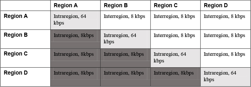
Region pairings are bidirectional, so the setting that defines the policy for Region A to Region B is the same as the setting that defines the policy for Region B to Region A. As a result, the redundant policies are blacked out in the table. Communication between two devices in the same region are considered intraregion calls. Unified CM allows administrators to define each pairing between regions, but for most configurations, administrators only care about having a single policy for intraregion calls and a different policy for interregion calls, regardless of which regions are involved. Unified CM facilitates this type of configuration while also allowing for exceptions on an as-needed basis. Figure 6-19 visually depicts what this would look like.
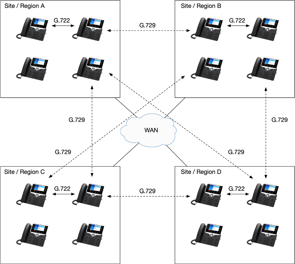
Figure 6-19 Codec Selection Between Four Regions
Figure 6-19 shows how calls between phones inside a region are configured to use the G.722 codec, while calls between regions are configured to use G.729. That said, this description is actually not completely technically accurate. When you configure a codec between two regions, you are not configuring a codec at all. You are actually configuring the maximum amount of bandwidth you would like Unified CM to allow for calls between the two devices. This means that if you select G.722, you are really saying that you want audio calls to consume no more than 64 kbps of bandwidth (before the overhead associated with L4/L3/L2 headers). To determine which codec is actually used, Unified CM makes a decision based on the capabilities advertised by each of the endpoints involved in the call, as well as the preference order defined in the audio codec preference list.
Audio Codec Preference Lists
![]()
An audio codec preference list allows you to specify the relative priority of one audio codec over another. This means that you can prefer a lower-bandwidth codec such as G.729 over a higher-bandwidth codec such as G.711μ-law, for example. So if a region is configured to allow calls with up to 64 kbps of bandwidth, if G.729 appears higher in the audio codec preference list, G.729 is used even though the region allows for enough bandwidth for a G.711 call. Audio codec preference lists are configured by navigating to Unified CM Administration > System > Region Information > Audio Codec Preference List. Unified CM comes with two lists by default: the factory default lossy and factory default low loss lists. The factory default lossy list prioritizes codecs that are designed to deal with packet loss better than other codecs, even if the overall quality is not as high; the factory default low loss list prioritizes the highest-fidelity codecs, even if they behave poorly when there is packet loss. Figure 6-20 shows an example of the factory default lossy preference list.
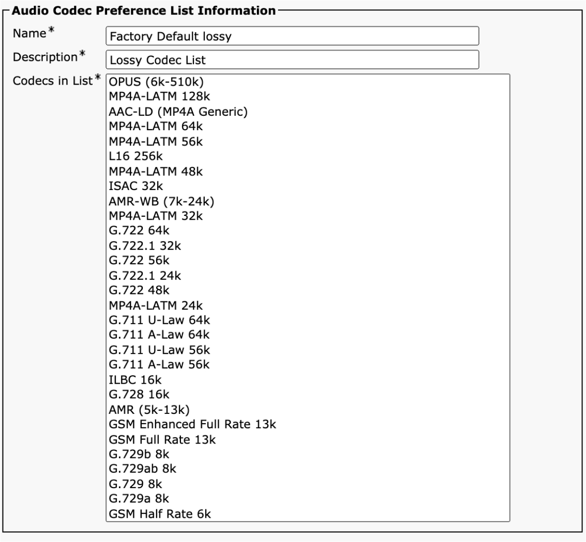
Figure 6-20 Factory Default Lossy Audio Codec Preference List
The first important note about audio codec preference lists is that you cannot add or remove codecs from the list. The codecs on the list come preinstalled with Unified CM and cannot be changed. This means that to support a new audio codec, Unified CM must be upgraded. Fortunately, new audio codecs don’t come along very often. The factory default lists cannot be modified. If you want to make a change, you must click the Copy button to copy one of the factory default lists and then reorder the codecs as you like.
You can see in the list that each codec has an amount of bandwidth associated with the codec. A few codecs are variable-rate codecs. In the case of variable-rate codecs, such as Opus, Unified CM attempts to negotiate the highest rate possible, based on the region configuration. Just because the Opus codec can go as high as 510 kbps does not exclude it from being advertised if the region pairing only allows for 64 kbps of bandwidth. In this case, Opus will be negotiated with a max bit rate of 64 kbps.
Furthermore, the region relationship between two endpoints and the audio codec preference list are used with call signaling to establish a session and select a codec. Just because a region relationship is 64 kbps doesn’t guarantee that G.722 or G.711 will be used as the codec. Both devices involved in the call signaling must agree on a codec that is within the bandwidth requirements defined by the region relationship. This could be G.729 (8 kbps) because that is the only common codec supported by both endpoints and is less than 64 kbps. Similarly, when Unified CM makes an offer such as a SIP early offer INVITE, it includes all available audio codecs that meet the bandwidth requirements of the region relationship. In this early offer scenario, the remote endpoint can select an available codec from the list in the offer when responding with an answer.
Configure Interregion and Intraregion Policies
Now that you understand the fundamentals of how regions work and the concept of audio codec preference lists, we can look at how to configure the interregion and intraregion policies. The most basic way of configuring region policies is through a variety of service parameters. Navigate to Unified CM Administration > System > Service Parameters > Server > Cisco CallManager and find the section System - Location and Region section (see Figure 6-21). This section has some parameters for the locations call admission control feature as well, but we can ignore those for now as we will come back to them in the next section.
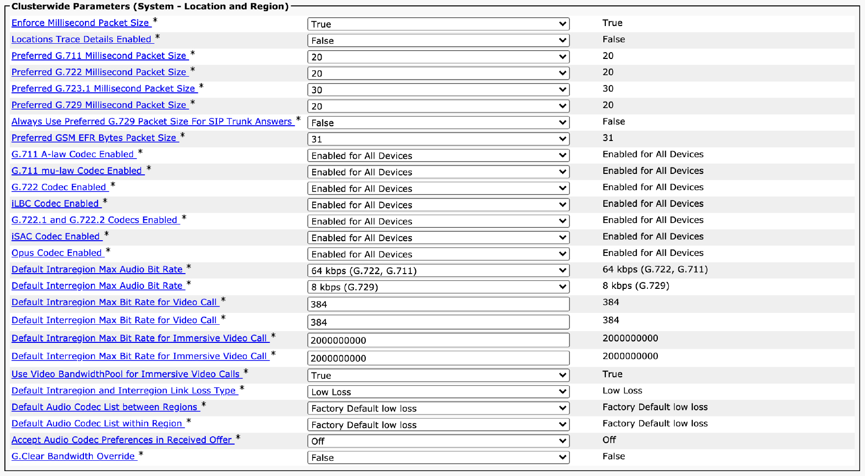
Figure 6-21 Location- and Region-Related Service Parameters
![]()
Recall that there is no way to remove a codec from an audio codec preference list. However, you can see in the list of service parameters that there are ways to enable and disable codecs on a global basis. There are individual parameters for a variety of codecs, such as G.722 Codec Enabled and Opus Codec Enabled. Each of these parameters has three settings:
• Enabled for All Devices: All devices that support this codec are allowed to negotiate it, provided that the regions pairing allows it based on the bandwidth consumed by the codec.
• Disabled: This codec is never negotiated between devices.
• Enabled for All Devices Except Recording-Enabled Devices: As the name implies, this is similar to Enabled for All Devices except that if one of the devices in the call is enabled for call recording, this codec is not permitted. The primary reason for this setting is that many call recording servers don’t support more advanced codecs such as Opus or iSAC, and negotiating one of those codecs will cause call recording to fail.
Regions allow you to specify not only the maximum audio bit rate for calls within and between regions but also the maximum amount of video bandwidth allowed for standard video calls as well as immersive (telepresence) video calls.
If you only care to set policy for all interregion and intraregion calls, you can do so by using the service parameters shown previously. There are size parameters that control the global region settings for audio, video, and immersive calls:
• Default Intraregion Max Audio Bit Rate: This parameter allows administrators to select the maximum audio bit rate and, indirectly, the subset of codecs allowed for calls between devices in the same region. The default is 64 kbps, which means that some of the higher bit rate codecs, such as AAC-LD, are not negotiated by default. This parameter lets you select from specific values that correspond to groups of codecs. You can reference the audio codec preference list to determine how much bandwidth a codec consumes.
• Default Interregion Max Audio Bit Rate: This parameter behaves the same as the Default Intraregion Max Audio Bit Rate setting but applies to calls between devices in different regions.
• Default Intraregion Max Bit Rate for Video Call: This parameter allows administrators to define the maximum amount of bandwidth to use for video calls between devices in the same region. As discussed later in this chapter, this can be either the bandwidth just for the video portion of the call or the combined session bandwidth for both audio and video. This parameter accepts an arbitrary integer value and represents the bitrate in kilobits per second.
• Default Interregion Max Bit Rate for Video Call: This parameter behaves the same as the Default Intraregion Max Bit Rate for Video Call setting but applies to calls between devices in different regions.
• Default Intraregion Max Bit Rate for Immersive Video Call: This parameter allows administrators to define the maximum amount of bandwidth to use for video calls between immersive video systems. Only TX/IX Series video units (and older CTS Series units) are considered immersive video systems. This setting is similar to the Default Intraregion Max Bit Rate for Video Call parameter but defines the setting specifically for immersive devices. It accepts an arbitrary integer value in kilobits per second and defaults to 2000000000, which basically means unlimited bandwidth up to the capabilities of the device.
• Default Interregion Max Bit Rate for Immersive Video Call: This parameter behaves the same as the Default Intraregion Max Bit Rate for Immersive Video Call parameter but applies to calls between devices in different regions.
Most, if not all, video calls also have an audio channel associated with the call. When a call is negotiated as a video call, Unified CM can either treat the audio and video bandwidth separately or treat the audio portion of the call as part of the video bandwidth. In other words, if a region is configured to allow 384 kbps of video bandwidth, this can mean 320 kbps of video plus 64 kbps of audio (or any other combination that adds up to 384 kbps, such as 376 kbps of video plus 8 kbps of audio), or it can mean 384 kbps of video plus whatever is configured for the audio bit rate between the two regions. The setting that controls this is not shown in Figure 6-21 because it appears in a different section of the service parameters configuration page. The parameter is called Deduct Audio Bandwidth Portion from Audio Pool for a Video Call and is located in the Call Admission Control section of the service parameters page. When this parameter is set to False, the default value, the video bandwidth determines the overall session bandwidth allowed, including both audio and video. If it is set to True, the audio bandwidth is determined separately.
The final step in configuring regions is to create the regions, add any exceptions to interregion or intraregion settings, and assign the regions to device pools. To add and configure a region, navigate to Unified CM Administration > System > Region Information > Region. Figure 6-22 shows the configuration page for a sample region.
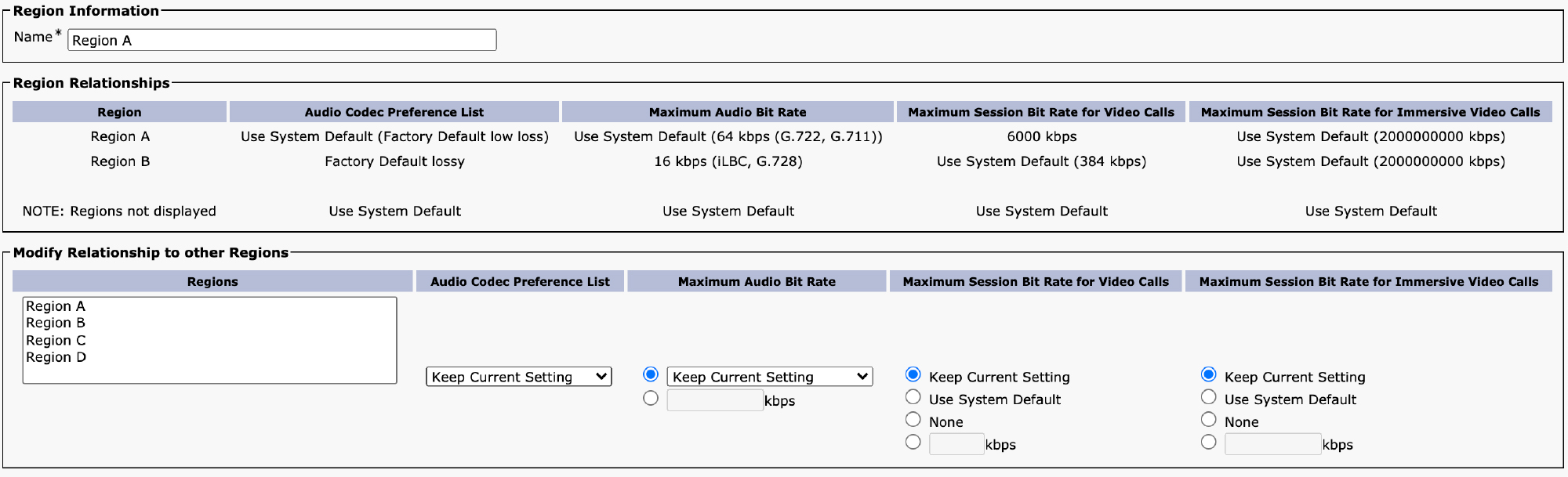
Figure 6-22 Region Configuration
When adding a region, the only parameter that is required is the name. If you do not modify any of the other settings, Unified CM uses the system default settings for interregion and intraregion bandwidth for audio, video, and immersive video calls. By default, the Region Relationships section of the page does not show any other regions because only regions where a non-system default setting is configured are shown. For the sake of example, we have shown a couple of settings being overridden in Figure 6-22. In this example, Region A is being configured to override the video call session bandwidth within the region to 6000 kbps. You can see that this is intraregion because this is the relationship between Region A and itself (Region A). The example also shows that Region A is configured to use the factory default lossy audio codec preference list and up to 16 kbps of audio bandwidth for calls between the two regions.
![]()
The Modify Region Relationships section of the configuration allows you to change any of the four settings: Audio Codec Preference List, Maximum Audio Bit Rate, Maximum Session Bit Rate for Video Calls, and Maximum Session Bit Rate for Immersive Video Calls. Note that the text that appears on this page depends on the Deduct Audio Bandwidth Portion from Audio Pool for a Video Call setting. If that parameter is set to True, the page shows Maximum Video Bit Rate for Video Calls instead of Maximum Session Bit Rate for Video Calls. For each setting, you can keep the current setting, use the system default value, or set an explicit value. This means you can modify one setting while keeping the other parameters set to the system defaults.
The final configuration step is to assign the regions you have configured to device pools and then assign those device pools to devices. Once you have your regions configured correctly, you might want to limit the number of calls allowed between the regions. Unified CM provides features that allow you to set limits for the maximum amount of bandwidth allowed for audio and video calls. This is called call admission control.
Note
To stop Unified CM from advertising video capabilities in an offer (through m=video lines in the SDP body of a SIP message), simply set the video bandwidth between two regions to None. This method of blocking the advertisement of video capabilities is usually leveraged on SIP trunks interfacing with CUBE when connecting to the PSTN, as most Internet telephony service providers (ITSPs) do not support video. You should place the SIP trunk in its own region and set the Session Bandwidth for Video parameter to None for pairings from the CUBE region to any regions containing video-capable devices.
Call Admission Control (CAC)
The regions feature allows you to control which codecs and how much bandwidth is allowed for individual calls between two devices that might be in different sites, but it does not control the aggregate amount of bandwidth allowed for all calls between those two sites. Call admission control (CAC) is a feature that allows you to limit the aggregate bandwidth allowed between two logical groupings of devices. These groups are called locations in the enhanced location call admission control (ELCAC) feature in Unified CM. Although regions and locations typically logically group the same sets of devices (for example, all phones at a specific remote site are assigned a region called Remote Site 1 and also assigned a location called Remote Site 1), these two groupings are completely independent of each other and do not have to match.
Before the ELCAC feature was introduced, Unified CM supported a very basic location CAC feature that allowed for tracking of bandwidth across either hub-and-spoke or fully meshed topologies. ELCAC added the ability to track bandwidth across arbitrarily complex network topologies as well as track bandwidth across multiple clusters that may share bandwidth to a given location.
Location Bandwidth Manager Service
Configuring ELCAC begins with activating an essential service needed to make the feature work. If you do not activate the Cisco Location Bandwidth Manager (LBM) service, you can configure ELCAC, but by default it does not restrict any calls from being completed, even if the calls exceed the bandwidth limits put in place. Before configuring ELCAC, be sure to navigate to Unified CM Serviceability > Tools > Service Activation and activate the Cisco Location Bandwidth Manager service. You can activate this service on whichever servers in the cluster you wish, but it is strongly recommended that you activate the service on all servers in the cluster that are running the Cisco CallManager service.
Once the LBM service has been activated, you should create LBM groups. This is not required, but to ensure high availability for the LBM service, you should create an LBM group for each server in the cluster running LBM. An LBM group allows you to configure a primary LBM server and backup LBM server. To understand why you should configure a group for each server, you need to understand the logic Unified CM uses to find the LBM service.
![]()
The Cisco CallManager service first looks to see if an LBM group is configured and associated with the server on which the service is running. If it is, the Cisco CallManager service uses the primary and backup LBM servers listed in the LBM group. If no LBM group is assigned to the server, the Cisco CallManager service looks locally for the LBM service, and if the service is running on the same server, it works; however, if the LBM service fails on the local server for whatever reason, the Cisco CallManager service does not look elsewhere in the cluster for another LBM service. If the Cisco CallManager service cannot find an active LBM service based on this logic, it looks at the service parameter named Call Treatment When no LBM Available, which defaults to Allow. This means that, by default, if LBM is not available, calls are permitted even if there might not be enough bandwidth for those calls.
The recommendation is to create an LBM group for each server in the cluster running the Cisco CallManager service and, for each group, to assign the server to which the LBM group will be assigned as the primary and then assign as a backup a second node that is in close geographic proximity to the primary node. Figure 6-23 shows how this would work for a five-server cluster with one publisher and four servers running the Cisco CallManager service.

Figure 6-23 LBM Group Topology
In this example, you would create four LBM groups, each with the local server as primary and then the closest server as the backup. For example, you would assign LBM Group 1 to Unified CM 1, LBM Group 2 to Unified CM 2, and so on. To configure an LBM group, navigate to Unified CM Administration > System > Location Info > Location Bandwidth Manager Group. Figure 6-24 shows the sample configuration for an LBM group.

Figure 6-24 LBM Group Configuration
You can assign an arbitrary name to the group and then assign active and standby servers for the group. Once you have created an LBM group for each server in the cluster, you need to assign the LBM groups to the appropriate servers. This is done from Unified CM Administration > System > Cisco Unified CM. Select each server running the Cisco CallManager service and assign the LBM group you configured for that server.
Configure Enhanced Location Call Admission Control (ELCAC)
Now that you have activated the LBM service and created and assigned LBM groups, you need to understand how ELCAC works. ELCAC is a model-based static CAC mechanism. To configure ELCAC, you must configure locations and links to model the topology of the network to represent how the WAN network topology routes media between groups of endpoints for end-to-end audio, video, and immersive calls. Although Unified CM provides configuration and serviceability interfaces in order to model the network, it is still a “static” CAC mechanism that does not consider network failures, alternate paths, or changes made to the network; therefore, the model needs to be updated when the network topology changes. ELCAC is also call oriented, and bandwidth deductions are per-call not per-stream, so asymmetric media flows where the bit rate is higher in one direction than in the other always deduct for the highest bit rate. In addition, unidirectional media flows are deducted as if they were bidirectional media flows.
ELCAC incorporates the following configuration components to allow you to build the network model using locations and links:
![]()
• Locations: A location represents a LAN or aggregation point in a network. It could contain endpoints or could simply serve as a transit location between links for WAN network modeling. For example, an MPLS provider could be represented by a location. Devices in a given location are generally considered to have unrestricted bandwidth, but ELCAC allows for intraregion restrictions as well.
• Links: Links interconnect locations and are used to define bandwidth available between locations. A link logically represents the amount of bandwidth available for different types of calls between two locations.
• Weights: A weight provides the relative priority of a link in forming the effective path between any pair of locations. The effective path is the path used by Unified CM for the bandwidth calculations, and it has the least cumulative weight of all possible paths. Weights are used on links to provide a cost for the effective path and are relevant only when there is more than one path between any two locations.
• Path: A path is a sequence of links and intermediate locations connecting a pair of locations. Unified CM calculates least-cost paths (lowest cumulative weight) from each location to all other locations and builds a map of the various paths. Only one effective path is used between any pair of locations.
• Effective path: The effective path is the end-to-end path with the least cumulative weight. As far as Unified CM is concerned, all traffic between two locations only traverses the effective path.
• Bandwidth allocation: Bandwidth allocation refers to the amount of bandwidth allocated in the model for each type of traffic: audio, video, and immersive video. These bandwidth deductions are taken based on the region configuration as well as the codecs that are actually negotiated for a call.
• Location Bandwidth Manager (LBM): As discussed previously, the service that assembles a network model from configured location and link data in one or more clusters determines the effective paths between pairs of locations, determines whether to admit calls between a pair of locations based on the availability of bandwidth for each type of call, and deducts (reserves) bandwidth for the duration of each call that is admitted. When using ELCAC, the Cisco CallManager service makes a request to the LBM service for every call.
To best understand how these constructs come together, refer to Figure 6-25, which shows a sample topology using ELCAC.

Figure 6-25 ELCAC Sample Topology
This is an example of a fairly simple network; however, these concepts extend to much more complex topologies. In this example, you would configure six locations:
• Remote Site 1
• Remote Site 2
• MPLS WAN
• Campus 1
• Campus 2
• Campus 3
Each of these locations represents a logical grouping of devices or a transit point in the network. The name of a location is important if you plan on implementing ELCAC between multiple clusters because the names of locations must match identically if you plan on creating links between locations on different clusters or adding devices on multiple clusters to the same location. Be absolutely certain that if you are configuring the same location on multiple clusters that the name matches.
Connecting each of the locations is a link. In some cases, such as between the MPLS WAN and the Campus 1 location, there are two links in the real network. Unfortunately, Unified CM does not know the routing tables or how traffic is being forwarded on redundant links, so depending on how you model the network, you would assume a particular route for the traffic. To be conservative, you would want to assume that the traffic is using the lower-speed link, but if you model the network so that Unified CM knows about both links, it assumes that the better link is always available. In fact, when modeling the network, you do not need to add two links between Campus 1 and the MPLS WAN locations because the lower-cost link will never be used.
Each link is assigned an arbitrary weight that you can use to influence which link Unified CM considers when building the effective path between two locations. The link weight does not necessarily have to correspond to the bandwidth available on the link. The weight simply helps determine which path will be used, regardless of the bandwidth available. In Figure 6-25, you can see that a weight of 10 is assigned to almost every one of the links except for one of the two links between Campus 1 and the MPLS WAN. Setting the higher-bandwidth link with a lower weight ensures that the link is used for calculations.
When building the effective path between Remote Site 1 and Campus 3, Unified CM takes the path Remote Site 1 → MPLS WAN → Campus 1 → Campus 3; however, when calculating the effective path between Campus 3 and Campus 2, the effective path is just Campus 3 → Campus 2. Unified CM assumes that traffic between Campus 2 and Campus 3 traverses the direct link between the two instead of going up through Campus 1. If for some reason the network topology were such that the normal traffic pattern was through Campus 1, you could modify the weight of the Campus 2–to–Campus 3 link to be higher than 20. Since the weights of the two links between Campus 1 and Campuses 2 and 3 are each 10, the cumulative weight to get from Campus 3 to Campus 2 via Campus 1 is 20. This means that as long as the direct link between Campus 2 and Campus 3 is higher than 20, the path between Campus 1 will be selected as the effective path.
To configure this topology in Unified CM, navigate to Unified CM Administration > System > Location Info > Location. Figure 6-26 shows the location configuration page for adding a new location.

Figure 6-26 Location Configuration
You must provide a name for the location, and Unified CM always prompts you to add at least one link from the location you are creating to another location. If this is the first location you are creating, you might not have another location to create a link to yet. You can select the Hub_None location, which is a default location that comes with Unified CM, to create the initial link and then you can delete it later. In this case, say that you are adding the Remote Site 2 location, which, based on the topology diagram in Figure 6-25, has a link to the MPLS WAN location. To create this link, select the location to which this link connects (MPLS WAN in this case) and then configure the weight and allowed bandwidth for audio, video, and immersive video.
If you click the Advanced button link at the bottom, you expose the Intra-location - Bandwidth for Device Within This Location setting, which allows you to specify bandwidth limits for calls between devices in the same location. This is typically left at the default setting, Unlimited, which is why it is hidden in the advanced options.
Once you have saved the new location, you see a screen like the one shown in Figure 6-27. On this page, you can add, delete, or modify all the links that are associated with this location. Links are bidirectional, which means that if you look at the MPLS WAN location, you see the same link pointing back to the newly added Remote Site 2 location.
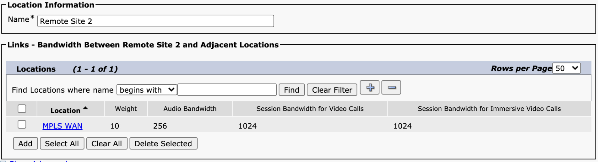
Figure 6-27 Location Configuration After Saving
Once you have modeled your network by configuring locations and links, the last step is to assign locations to your devices. This can be done by configuring the location on the device itself or, if you are using the device mobility feature, it can be assigned dynamically based on the physical location of the device on the network. Note that if you are not using device mobility, you must assign the location on the device itself. The location assigned on the device pool does not apply as there is no “use default” setting for a location on the device configuration page, so whatever is configured on the device is used. By default, all devices are in the Hub_None location.
Also be careful that you do not leave devices in a location to which there are no links. If a location has no path to another location, you cannot make any calls between those two locations.
In addition to the Hub_None location, there are two other special locations that come preconfigured with Unified CM: the Phantom and Shadow locations. These two locations serve similar purposes, but the Phantom location comes preconfigured for the legacy location call admission control feature and should not be used with ELCAC. The Shadow location should be used on SIP trunks that point to other Unified CM clusters that are also performing ELCAC. The Shadow location does not have links associated with it and just indicates to Unified CM that it should transmit information to the other cluster about the originating location and should expect information from the other cluster regarding the terminating location.
Automated Alternate Routing (AAR)
When a call fails due to insufficient bandwidth between locations, the default behavior is to play a reorder tone to the user and display a message on the phone indicating that the call could not be completed. This is not an ideal user experience. If the originating and terminating endpoints both have local PSTN connectivity that does not rely on the WAN, the automated alternate routing (AAR) feature can be used to automatically reroute the call over the PSTN if there is insufficient bandwidth. The biggest disadvantage to rerouting over the PSTN is that PSTN audio is typically narrowband (G.711 at best) and does not support video, so the experience for the user will be impacted, but given the alternative of blocking the call entirely, routing over the PSTN is usually the best available option.
Figure 6-28 illustrates how the AAR feature works. The figure shows the following steps:
![]()
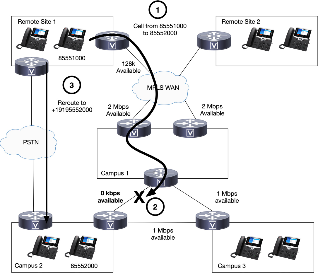
Figure 6-28 AAR in Action Example
Step 1. User 85551000 in Remote Site 1 dials user 85552000 at Campus 2.
Step 2. Unified CM attempts to route the call, and ELCAC determines that the effective path between Remote Site 1 and Campus 2 is via the Remote Site 1 → MPLS WAN link followed by the MPLS WAN → Campus 1 link followed by the Campus 1 → Campus 2 link. Because there is no bandwidth available on the Campus 1 → Campus 2 link, the call is rejected. (Note that there would be bandwidth available if the call were to take the path from Campus 1 to Campus 3 and then to Campus 2, but ELCAC only considers the effective path and does not consider other paths even if one link is congested.)
Step 3. If AAR is configured, AAR transforms the called party number to a number that is reachable via the PSTN and reroutes the call over the PSTN.
In order for step 3 to work, there are two things Unified CM must do. First, it must determine how to reach 85552000 via the PSTN. The number 85552000 is not an E.164 number, so sending those digits to the PSTN would result in a call failure. Once it has transformed the digits to something reachable via the PSTN, Unified CM must match a route pattern that routes the call to the local PSTN gateway. Let’s examine each of these two steps.
The first step is transforming the digits. There are three different places that can affect the number getting into the form where it can be called via the PSTN. The first is the AAR destination mask, which can be configured on a line. Figure 6-29 shows the AAR Settings section for configuring a line in the Unified CM Administration user interface.
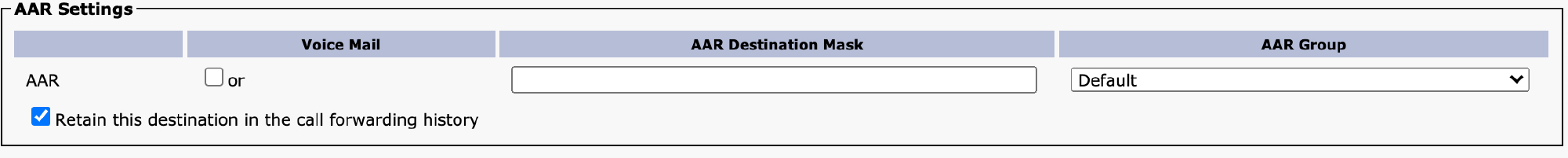
Figure 6-29 AAR Settings on a Line
The AAR Destination Mask setting allows you to mask the directory number to transform it to an E.164 number. This transformation can convert the number to anything you like. For example, if the directory number does not have a DID associated with it, you can convert the number to an IVR system or a reception desk at the destination site. In this case, you could configure the AAR mask as +19195552000 to match the DID associated with the 85552000 extension. The other important setting in the AAR Settings section is AAR Group. For AAR to function, the originating and terminating devices must be in an AAR group. As you will see in a moment, you can put all phones in the same AAR group if you do not need additional digit manipulation when calling from one location to another.
The second way that the number can be transformed for the purposes of AAR is through the External Phone Number Mask parameter. This is usually the preferred method of transforming the number because the external phone number mask usually needs to be configured anyway to ensure proper calling party number presentation for PSTN calls, so this field ends up serving a dual purpose.
![]()
Note
In order for AAR to work, you must have either an external phone number mask or an AAR destination mask configured. This means that if your directory number is already in a globalized form that can be reached over the PSTN—for example, if the directory number is in +E.164 format already—you must still configure a mask if you want AAR to function, even if the mask is identical to the directory number.
The final mechanism available to modify the directory number for the purposes of AAR is to use prefixes configured as part of the AAR group configuration. The general design recommendation is to not use this mechanism and instead transform the number to +E.164 format and ensure that phones can dial a number to the PSTN by directly dialing the number in +E.164 format. However, if you cannot do this for some reason, AAR allows you to prefix digits to the transformed number, depending on the source and destination groups. To configure an AAR group, navigate to Unified CM Administration > Call Routing > AAR Group. Figure 6-30 shows the AAR group configuration page.
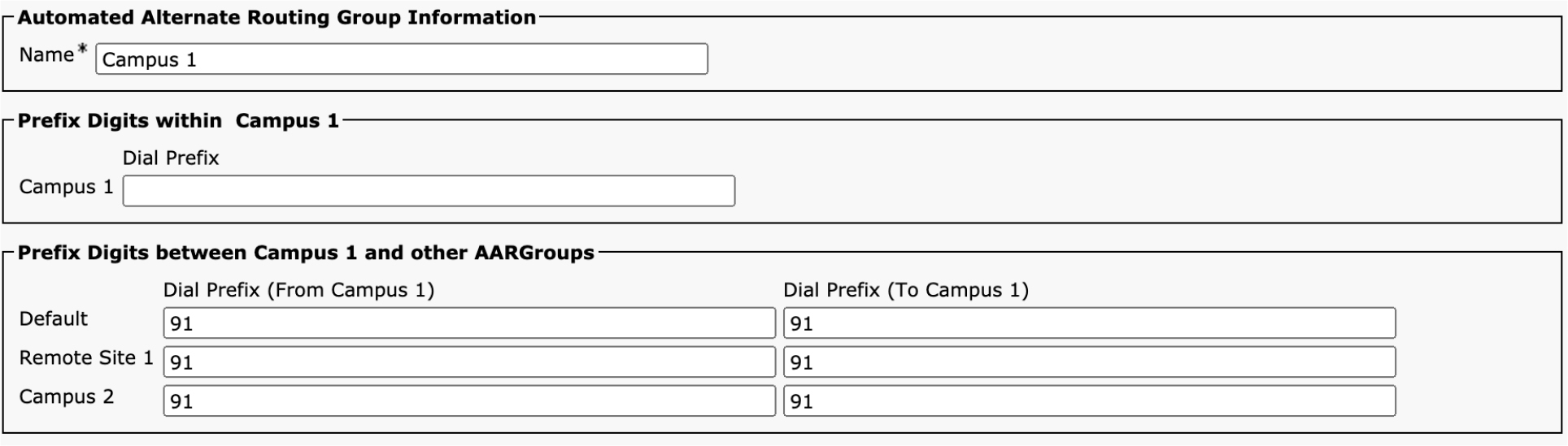
Figure 6-30 AAR Group Configuration
The AAR group prefix digits configuration allows you to specify what digits to prefix when rerouting a call from one AAR group to another. In this case, you can see that 91 is being prefixed for calls from the Campus 1 AAR group to all the other AAR groups. (In addition, calls from all the other AAR groups will get 91 prefixed to calls destined to the Campus 1 AAR group.) If using a configuration like this, you might have an external phone number mask that transforms the directory number to a 10-digit national number (for example, 9195552000) and then use the AAR prefix to prefix the access code needed to make this a PSTN call. Best practice is to not leverage this mechanism and just make sure numbers are transformed to +E.164 format and that a route pattern exists to match the +E.164 number for routing to the local gateway.
After the number has been transformed to a number reachable through the PSTN, the call must be routed. This is done by placing a call to the transformed number, but instead of using the line/device calling search space of the device, the AAR calling search space is used. The AAR calling search space can have permissions to dial numbers via the PSTN that the user might not normally be allowed to dial directly. For example, if the call failure is between two phones in different countries, you might allow AAR to place an international call when the user is not normally allowed to place international calls.
If using the design guidance of transforming the number to +E.164 format, you can simply have a single route pattern matching +! with urgent priority (because AAR calls are always presented enbloc, so you do not have to worry about digit-by-digit dialing), and that route pattern can point to a route list with a local route group configured. You might even choose to define one of the local route groups as the AAR local route group and then, for each device pool, specify the route group that should be used for placing AAR calls for devices where that device pool is configured. With a +E.164 dial plan, enabling AAR is very simple: Just ensure that you have a single AAR group with no prefixes configured assigned to all directory numbers, ensure that you have an external phone number mask in +E.164 format, and ensure that the AAR calling search space is configured to point to a partition with a pattern that can route all calls to the local route group.
Troubleshooting and Monitoring Enhanced Location Call Admission Control
After you have configured locations and associated them with devices, you can place calls, and Unified CM ensures that you do not exceed the limits of your network, based on the configuration, and it reroutes to the PSTN as needed if you have enabled AAR. Unified CM provides several features that allow you to monitor and troubleshoot ELCAC to understand why calls may or may not be working between two locations.
The first set of tools are available under Unified CM Serviceability > Tools > Locations. The first option here is the Topology menu, which allows you to view the list of all locations and the links associated with a location. For example, Figure 6-31 shows the information for the MPLS WAN location.

Figure 6-31 ELCAC Topology View in Unified CM Serviceability
![]()
The most useful feature in Unified CM Serviceability for diagnosing issues with ELCAC is the Effective Path submenu, which allows you to select any two locations and view the path between those two sites, as calculated by Unified CM, as well as the bandwidth configuration and real-time available bandwidth. For example, Figure 6-32 shows the path between the Campus 1 and Remote Site 1 locations.

Figure 6-32 Example Path Between Two Unified CM Locations
The Quick Path Overview section shows information about the most constrained link on the route along the path between the two locations. This is effectively the available bandwidth between the two locations. The Detailed Path View section shows the details of each location and link so you can see how much bandwidth is configured and available at each hop along the path. In this example, you can see that there is no video bandwidth available between these two locations because the link between MPLS WAN and Remote Site 1 is full. This means that no additional video calls are permitted on this link, although audio calls and immersive video calls are still allowed. The Effective Path menu is the first place you should look when trying to understand why a call between two locations is being rejected.
You can also use the Real Time Monitoring Tool (RTMT) Performance menu to monitor the available bandwidth on links as well. In this case, you can just monitor specific links or locations and not the effective path between locations. Figure 6-33 shows the available bandwidth for audio and video for the link between Campus 1 and the MPLS WAN as well as the link between the MPLS WAN and Remote Site 1.

Figure 6-33 RTMT View of ELCAC Counters
These counters can also be polled through the PerfMon API that is part of the Serviceability XML API available on Unified CM. (For more information on the Serviceability XML API, visit developer.cisco.com.) You can see that the example in Figure 6-33 is monitoring for the BandwidthAvailable and VideoBandwidthAvailable counters. You can also see that it is monitoring the OutOfResources counter, which increments any time a call is denied because of a CAC failure. These are good counters to monitor because if the out-of-bandwidth counters are incrementing, you might want to consider adding bandwidth to those links.
If you want to dig in deeper to detect CAC failures, you can look in the SDL traces or call detail records. The first clue of a CAC failure appears in the call detail records. Unified CM indicates cause code 125 for a CAC failure, so if you see this cause code, it is likely to be CAC related. To delve deeper, you can examine the SIP signaling for a call from a phone destined to another location. When Unified CM rejects a call due to insufficient bandwidth, the response to the INVITE message is a 488 Not Acceptable Media error, as shown in Example 6-2.
![]()
Example 6-2 SIP Response for a CAC Failure
SIP/2.0 488 Not Acceptable Media
Via: SIP/2.0/TCP 10.122.251.105:49820;branch=z9hG4bK02a02cad
From: “Test Phone 2” <sip:[email protected]>;tag=885a92d9bca800772f938f9b-61ae84eb
To: <sip:[email protected]>;tag=836~c1c9b4c0-de76-4127-bdc8-97f098ac0580-43759214
Call-ID: [email protected]
CSeq: 101 INVITE
Allow-Events: presence
Server: Cisco-CUCM12.5
Session-ID: 00000000000000000000000000000000;remote=565dd44100105000a000885a92d9bca8
Warning: 370 10.122.249.71 “Insufficient Bandwidth"
Reason: Q.850; cause=125
Remote-Party-ID: “Test Phone 1” <sip:[email protected];user=phone>;party=x-cisco-original-called;privacy=off
Content-Length: 0
You can see in the example that Unified CM provides a Warning header with the message Insufficient Bandwidth. If you want to look deeper in the SDL trace, just before the 488 is sent, you see the lines shown in Example 6-3.
Example 6-3 CAC Failure Messages in SDL Trace
00018315.001 |00:24:09.958 |AppInfo  |LBMIF: CI: 43759215 REGISTER 2,100,180,32 dev 0xf5f08e60
00018315.002 |00:24:09.958 |AppInfo  |LBMIF: device 0xf5f08e60 A:Y V:N I:N ; peer 0xf5f07af8 A:Y V:N I:N | UV:T QoS:F
00018315.004 |00:24:09.958 |AppInfo  |LBMIF: CI: 43759215 BW RSV>  dev 0xf5f08e60 13210859295534481424 audio 24
00018315.005 |00:24:09.958 |AppInfo  |LBMIF: RSV XML> (35) 13210859295534481424 Remote Site 1|Campus 1 A:Y,24 V:N,0 I:N,0 Force:0 Prec:5 Dpl:5
00018315.006 |00:24:09.958 |AppInfo  |LBMIF: Sending to ACTIVE LBM (svs-uc-alpha-test-cm1b.cisco.com)
00018316.001 |00:24:09.960 |AppInfo  |LBMIF: RSV XML< (35) 13210859295534481424 F A:Y,24 V:Y,0 I:Y,0
00018316.002 |00:24:09.960 |AppInfo  |LBMIF: CI: 43759215 BW RSV<F 13210859295534481424 FailureRC(2) AudioRC(8) VideoRC(2) ImmersiveRC(2)
00018316.003 |00:24:09.961 |AppInfo  |LBMIF: Erase transaction record as lbmStatus equals to LBM_BANDWIDTH_FAIL
If you want to get additional detail on the failure, you need to look at the LBM trace files that can be downloaded using RTMT or from the platform CLI. In the LBM trace files, you can see the bandwidth request coming from the Cisco CallManager service to LBM, as shown in Example 6-4.
Example 6-4 Bandwidth Request from Cisco CallManager to LBM
00001151.001 |00:40:15.963 |AppInfo  |LBMServer - Received from CallManager:
msg = {
  messageId = (37)
  msgkey = ()
  nofwd = (0)
choice = (reservationReq)
  reservationReq = (
    transId = (13210859295534481426)
    seqNum = (0)
    choice = (reserve)
    reserve = (
      sideA = (
loc = (Remote Site 1)
        fs_id = (SVS-UC-Alpha-Test-Cluster1:43759218)
        ext = ()
      )
      sideB = (
loc = (Campus 1)
        fs_id = (SVS-UC-Alpha-Test-Cluster1:43759219)
        ext = ()
      )
      cacSt = (0)
      precedLvl = (5)
      mlpp = (0)
      execOVR = (0)
      enforce = (0)
a_val = (1)
      v_val = (0)
      i_val = (0)
a_bw = (24)
      v_bw = (0)
      i_bw = (0)
      a_op = (0)
      v_op = (0)
      i_op = (0)
      ext = (<msg></msg>)
    )
    ext = ()
  )
}
In Example 6-4, you can see that this is a reservation request between Remote Site 1 and Campus 1 locations, and the request is for an audio call of 24 kbps. In the output, a stands for audio, v stands for video, and i stands for immersive. a_val set to 1 indicates that audio is being requested, and the a_bw value indicates 24 kbps. LBM then shows the attempt to allocate bandwidth along the path, as shown in Example 6-5.
Example 6-5 LBM Searching for Available Bandwidth
00001152.001 |00:40:15.963 |AppInfo  |LBM: RES_REC OP=RESERVE tid=13210859295534481426 A=24 M Entering IP=10.122.249.71 st=ringing FK=SVS-UC-Alpha-Test-Cluster1:43759219+SVS-UC-Alpha-Test-Cluster1:43759218:Campus 1->Remote Site 1
00001152.002 |00:40:15.963 |AppInfo  |LBM: RES_REC Enough for 24 on Vertex=Campus 1. Left=0, Calls=1
00001152.003 |00:40:15.963 |AppInfo  |LBM: RES_REC Enough for 24 on Vertex=MPLS WAN. Left=0, Calls=1
00001152.004 |00:40:15.963 |AppInfo  |LBM: RES_REC Enough for 24 on Vertex=Remote Site 1. Left=0, Calls=1
00001152.005 |00:40:15.963 |AppInfo  |LBM: RES_REC Enough for 24 on Edge Campus 1->MPLS WAN. Left=1976, Calls=1
00001152.006 |00:40:15.963 |AppInfo  |LBM: RES_REC NOT Enough for 24 on Edge MPLS WAN->Remote Site 1. Left=0, Calls=1. FAIL. (ProcessLocationHelper.cpp:163)
This triggers LBM to generate an alarm, as shown in Example 6-6.
Example 6-6 Out-of-Bandwidth Alarm Generated by LBM
00001152.007 |00:40:15.963 |AppInfo  |GenAlarm: AlarmName = LocationOutOfResource, subFac = Location Bandwidth ManagerKeyParam = , severity = 4, AlarmMsg = Name : MPLS WAN->Remote Site 1
ResourceType : 1
AppID : Cisco Location Bandwidth Manager
ClusterID : SVS-UC-Alpha-Test-Cluster1
NodeID : svs-uc-alpha-test-cm1b
The severity of this alarm is only level 4, so depending on your network management configuration, you might not alert on this. If you are using ELCAC, this is an alarm you might want to pay attention to because it indicates a CAC failure due to lack of bandwidth.
Most ELCAC issues are due to either misconfiguration or legitimate lack of bandwidth. Proper monitoring of counters and alarms so that administrators are aware of CAC failures can ensure that additional bandwidth is added to provide the call capacity needed by users at a location.
Exam Preparation Tasks
As mentioned in the section “How to Use This Book” in the Introduction, you have a couple of choices for exam preparation: the exercises here, Chapter 11, “Final Preparation,” and the exam simulation questions in the Pearson Test Prep software online.
Review All Key Topics
Review the most important topics in the chapter, noted with the key topics icon in the outer margin of the page. Table 6-5 lists these key topics and the page number on which each is found.
![]()
Table 6-5 Key Topics for Chapter 6
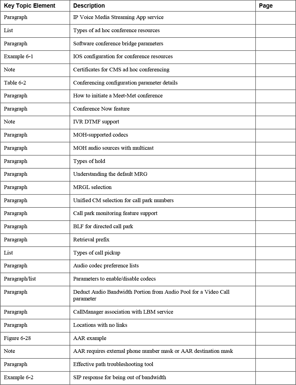
Complete Tables and Lists from Memory
There are no memory tables or lists for this chapter.
Define Key Terms
Define the following key terms from this chapter and check your answers in the glossary:
enhanced location call admission control (ELCAC)
interactive voice response (IVR)
IP Voice Media Streaming App service
media resource group list (MRGL)