Chapter 7. Unified CM Mobility
This chapter covers the following topics:
• Unified Mobility: This section details mobility-related features that allow remote users to connect to Unified CM, regardless of their physical location.
• Configure and Verify Extension Mobility: This section covers the Extension Mobility feature, which enables users to share phones while maintaining their own phone settings, including their directory number.
• Configure and Verify Device Mobility: This section covers the Device Mobility feature, which lets users take their devices to different sites and inherit settings that are specific to the site they are visiting.
This chapter covers the following CLACCM 300-815 exam topics:
• 6.1 Configure Cisco Unified Communications Manager Mobility
• 6.1.a Unified Mobility
• 6.1.b Extension Mobility
• 6.1.c Device Mobility
• 6.2 Troubleshoot Cisco Unified Communications Manager Mobility
• 6.2.a Unified Mobility
• 6.2.b Extension Mobility
• 6.2.c Device Mobility
Meeting business needs while also being as flexible as possible for end users and Unified CM administrators is one of the most important goals of Cisco collaboration products. For example, for users who need to be reachable via their desk phone number at any time, Unified CM administrators can implement the Unified Mobility feature Single Number Reach (SNR) to extend inbound calls to a user’s desk phone and the user’s desired remote device, such as a cell phone. A growing trend is the use of open concept office spaces. In these offices, users might not always be working in the same physical space or even the same physical building day in and day out, and endpoints cannot be individually assigned. In such settings, Unified CM administrators can leverage Extension Mobility to make it possible for users to share physical phones while maintaining their individual phone settings, including directory numbers. Similarly, there may be a need for a physical device to move with a person across the country or even between countries to a different remote office. Unified CM administrators need not fret because Unified CM Device Mobility lets users take their device to different locations and inherit settings that are specific to the site they are visiting, with little administrative intervention.
This chapter focuses on features mentioned previously as well as some of the smaller features provided by Cisco Unified Mobility, such as Move to Mobile and Intelligent Session Control.
Note
Two Unified Mobility topics that are not discussed in this book are Mobile Voice Access (MVA) and Enterprise Feature Access because these features have essentially been replaced by Mobile and Remote Access (MRA). Although MRA replaced some of the Unified Mobility features, it is not covered in this book because it is not covered on the CLACCM 300-815 exam. It is, however, covered on the Implementing Cisco Collaboration Cloud and Edge Solutions (CLCEI) 300-820 exam.
Although Cisco CallManager Express (CME) includes mobility features, the CLACCM 300-815 exam covers mobility features as they relate to Unified CM and not CME. Therefore, this chapter covers only Unified CM mobility and not CME mobility.
“Do I Know This Already?” Quiz
The “Do I Know This Already?” quiz allows you to assess whether you should read the entire chapter. If you miss no more than one of these self-assessment questions, you might want to move ahead to the “Exam Preparation Tasks” section of the chapter. Table 7-1 lists the major headings in this chapter and the “Do I Know This Already?” quiz questions related to the material in each of those sections to help you assess your knowledge of these specific areas. The answers to the “Do I Know This Already?” quiz appear in Appendix A, “Answers to the ‘Do I Know This Already?’ Quiz Questions.”
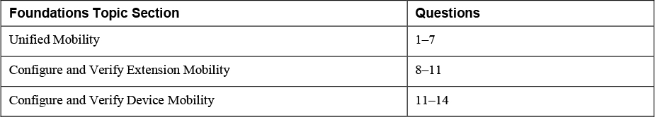
Table 7-1 “Do I Know This Already?” Foundation Topics Section-to-Question Mapping
1. Which of the following best describes the functionality that can be leveraged with Single Number Reach?
a. Single Number Reach allows users to log in to Extension Mobility via single sign-on (SSO).
b. Single Number Reach allows a user to receive calls at home or on a personal mobile phone when someone calls that user’s desk phone.
c. Single Number Reach is a mobility-related feature that adds functionality to Extension Mobility.
d. Single Number Reach allows users to call in to the corporate environment and place an outbound call as if it originated at their desk phone.
2. Which of the following is a feature of Intelligent Session Control?
a. It allows the remote destination to hang up and enables the user to resume the call on his or her desk phone.
b. It allows inbound calls from the remote destination to present as though they originated from the desk phone.
c. When an internal call is placed to a remote destination, Unified CM routes the call to the desk phone instead of to the remote destination.
d. When users are logged in to a phone, Intelligent Session Control knows when to log the user out of the phone.
3. Which of the following are common mistakes when configuring Single Number Reach? (Choose two.)
a. Enabling the user instead of the device for mobility
b. Leaving the Line Association checkbox unchecked
c. Setting up Single Number Reach for the wrong user
d. Applying the device calling search space and not the rerouting calling search space to the remote destination profile
e. Leaving the user’s PIN blank
4. When does Unified CM perform digit analysis for remote destination numbers?
a. In parallel with digit analysis for the desk phone number
b. After the Delay Before Ringing timer expires
c. When the user clicks the iDivert softkey
d. At the time of configuring the remote destination
5. Which of the following best describes the functionality of Move to Mobile?
a. It allows a user to hang up a call on his mobile phone and resume the call on his desk phone.
b. It is an Extension Mobility feature for mobile phones.
c. It allows a user to transition from her desk phone to her remote destination.
d. It allows a user to use Cisco Jabber on his mobile phone as a shared line.
6. To use Move to Mobile, what must be added to a phone?
a. A call forward button
b. A second directory number
c. A softkey
d. Extension Mobility
7. If Move to Mobile isn’t working, which checkbox should be reviewed on the Remote Destination Configuration page in Unified CM?
a. Enable Single Number Reach
b. Enable Move to Mobile
c. Enable Extend and Connect
d. Mobile and Remote Access (MRA)
8. Which of the following best describes Extension Mobility?
a. Extension Mobility allows a user to move her phone between campuses, and the phone will use local settings for the new campus.
b. Extension Mobility allows a user to transition a call from his desk phone to his mobile phone.
c. Extension Mobility allows agents to log in to a call queue with any phone, including a personal phone.
d. Extension Mobility allows a user to log in to a phone and temporarily use her device profile on the phone.
9. How can a remote Unified CM administrators tell which device profile is logged in to a phone with Extension Mobility?
a. Check the Extension Information section on the phone configuration page
b. Reset the phone
c. Check the CDP debugging information on the switch connected to the phone
d. Browse to the web page of the phone
10. Which of the following is a common mistake observed when configuring Extension Mobility?
a. Not enabling the Enable Mobility checkbox on the end-user page
b. Leaving the user logged in to the phone
c. Forgetting to set the primary extension on the end-user page
d. Using the EMCC URL instead of the EM URL
11. What should a Unified CM administrator do when a user can log in to a device but cannot log out?
a. Log the user out of the phone from the Extension Information section of the phone configuration page
b. Subscribe the phone to the Extension Mobility service
c. Subscribe the device profile to the Extension Mobility service
d. Have the user power cycle the phone
12. Which of the following best describes Device Mobility?
a. Device Mobility allows a user to move between sites and log in to local phone in order to apply her profile to the phone.
b. Device Mobility allows a user to move his phone between campuses, and the phone will use local settings for the new campus.
c. Device Mobility allows a user to connect her phone to Cisco Unified Communications Manager from external networks by using VPN-less access.
d. Device Mobility adds functionality to Extension Mobility Cross Cluster.
13. When is Device Mobility–related information applied to a phone?
a. When a device moves between Device Mobility groups
b. When a device changes subnets
c. When a device moves between physical locations and Device Mobility groups
d. When a device moves between physical locations but remains in the same Device Mobility group
14. In the following Unified CM trace snippet, is SEPD0EC35FFB4C4 at its home site, or has the user moved the phone to a new site?
01998726.003 |22:45:30.987 |AppInfo |DeviceManager::addMobileDevice - added mobile device to Device Mobility Route Table. DeviceName=SEPD0EC35FFB4C4, DeviceType=36225 IpAddr=6AD6320E, DevicePool=CDMX_DP(3529fd90-bf5e-8765-87b0-2ecf0d281cc7), RoamingDevicePool=SJ_DP(3f6bb86d-4d49-a843-24d6-bc928ecaf337), EMCCGeoLocationFilter=, DeviceGeoLocation=[], GeoLocationTokensMatched=0
a. There is not enough information to tell; the phone console logs are needed to determine the answer.
b. The phone is roaming.
c. The phone is not roaming.
d. It depends on whether the phone has changed Device Mobility groups.
Foundation Topics
Unified Mobility
This chapter covers the Unified Mobility features Single Number Reach (SNR), Move to Mobile, Intelligent Session Control, Extension Mobility, and Device Mobility. It shows the purpose of each of these features, how to configure them, and how to validate they’re working as expected. Furthermore, this chapter examines how to troubleshoot each feature. The Move to Mobile and Intelligent Session Control features rely heavily on SNR, so the chapter opens with the SNR feature.
Note
The terms mobile phone and remote destination are used interchangeably in this chapter.
Configure and Verify Single Number Reach
It is common for a person to have more than one phone number where he or she can be reached, such as a work number and a personal mobile device number or home phone number. Unified Mobility makes it easier to reach a user, no matter which phone the user is near. For example, say someone calls your work phone number and only the desk phone rings, but you are not at your desk, so you don’t receive the call. When SNR is configured, a caller can call your work number, and your personal mobile device or home phone will ring simultaneously with your desk phone (see Figure 7-1).
![]()

Figure 7-1 Single Number Reach Overview
Note
This chapter does not address the intricacies of call routing with Unified CM or CUBE. Instead, it discusses Unified Mobility configuration, validation, and troubleshooting. For more information about call routing with Unified CM, refer to Chapter 4, “Unified CM Call Routing and Digit Manipulation.” For more information on call routing with CUBE, see Chapter 8, “CUBE Call Routing and Digit Manipulation."
Figure 7-1 illustrates the following events that occur when Unified CM routes a call to a line associated with a remote destination:
Step 1. The phone with DN 1001 sends Unified CM a SIP INVITE to call DN 1000.
Step 2. Unified CM performs a digit analysis for the called number 1000, which is a line with an SNR remote destination profile (RDP). Before Unified CM extends the call to the IP phone with line 1000, a second digit analysis for the remote destination number (408-555-7890) is performed to determine the call should route to CUBE and, ultimately, the PSTN service provider.
Step 3. Unified CM extends the call to the IP phone, which begins to ring.
Step 4. Depending on some SNR timers (discussed later in the chapter), Unified CM might also extend the call to the SNR remote destination or wait for the configured delay interval before extending the call to CUBE and, ultimately, the PSTN service provider.
Step 5. The service provider extends the call to the cell phone with E.164 number +14085557890. At this point, the two phones continue ringing until one of the following occur:
• The called party answers the call on the IP phone 1000.
• The remote destination 408-555-7890 answers the call.
• The timers for the call expire. (Timers are discussed later in this chapter.)
• The calling party hangs up.
When a call is answered on a remote destination it can be ended by either the calling party or the remote destination. It is important to know that the calling party is placed on hold if the remote destination is the side that hangs up. Before fully disconnecting the call, Unified CM extends the phone call to the desk phone again. This hold allows the user to switch from the remote destination phone to the desk phone and continue talking with the calling party. The transition from the remote destination to the desk phone is accomplished with the Desk Pickup feature, and the default amount of time for Desk Pickup is 10 seconds. This timer value can be configured by changing the Maximum Wait Time for Desk Pickup parameter in the End User Configuration under Mobility Information, as shown in Figure 7-2. To disable Desk Pickup, set the Maximum Wait Time for Desk Pickup parameter to 0.
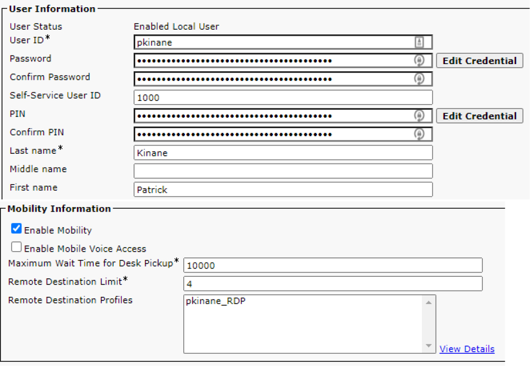
Figure 7-2 End-User Mobility Information Section
As an alternative to hanging up on the remote destination in order to use Desk Pickup, you can use the Enterprise Feature Access Code for Session Handoff to transition calls between the desk phone and remote destinations. Figure 7-3 shows a list of the default Enterprise Feature Access Codes.

Figure 7-3 Default Enterprise Feature Access Codes
Configure Single Number Reach
The next few sections detail how to configure SNR. Throughout the following examples, the end user's mobile phone serves as the remote destination, and 408-555-7890 is the number associated with the mobile device. The following steps are required to complete the implementation of Single Number Reach for a single user:
Step 1. Enable mobility on the end user: To enable mobility on the end user, navigate to Cisco Unified CM Administration > User Management > End User. Find and select the target end user and scroll to the Mobility Information section. Select the Enable Mobility checkbox (refer to Figure 7-2).
Step 2. On the phone configuration page, select the appropriate user in the Owner User ID field: Select the IP phone on which to enable SNR by navigating to Unified CM Administration > Device > Phone. In the Device Information section, ensure that the Owner toggle is set to User rather than Anonymous (Public/Shared Space). Select the appropriate user’s user ID in the Owner User ID dropdown. Save and apply configuration on the phone to complete the change.
Step 3. Create an RDP and associate it with the end user: To create an RDP and associate it with the end user, navigate to Cisco Unified CM Administration > Device > Device Settings > Remote Destination Profile. On the RDP page you can select Add New, and the page changes to the Remote Destination Profile Configuration page, as shown in Figure 7-4. Use this page to add the specific settings for the RDP.
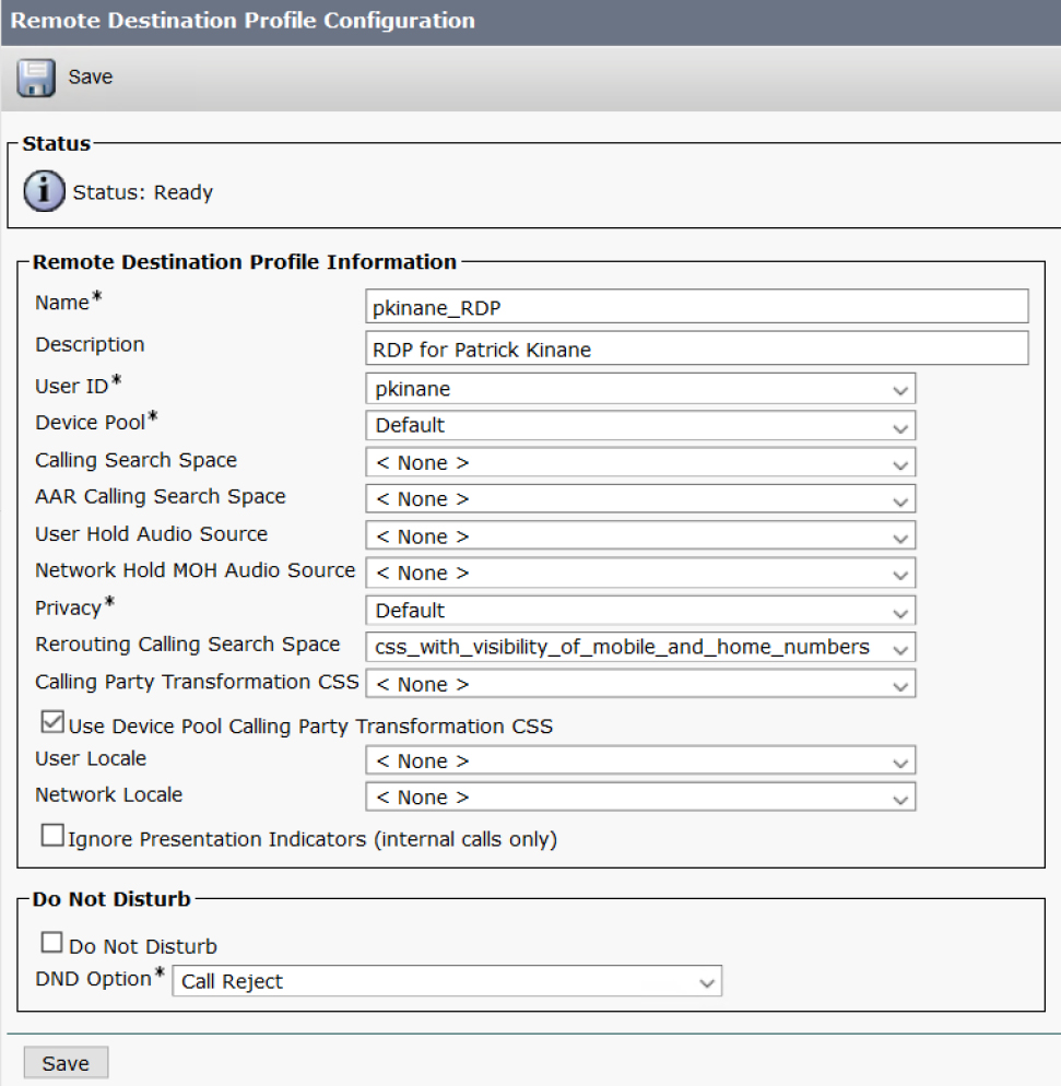
Figure 7-4 Remote Destination Profile Configuration Page
Ensure that the User ID field matches the user ID found on the end user configuration page. The route patterns used for routing calls to the remote destinations (typically the user’s mobile phone or home phone) must be accessible to the rerouting calling search space configured on the RDP.
Note
Notice that the calling search space applied to the RDP for SNR to work is the rerouting calling search space and not the typical device calling search space. This is because calls sent to the remote destination are treated similarly to calls that are forwarded. In Figure 7-4 you can see that no device calling search space is configured, but a rerouting calling search space is configured.
Step 4. Add a directory number to the RDP: When you click Save, the page refreshes and shows the Add Successful status message (see Figure 7-5). Now you should see the option to add a directory number to the RDP, along with the option to add a new remote destination.
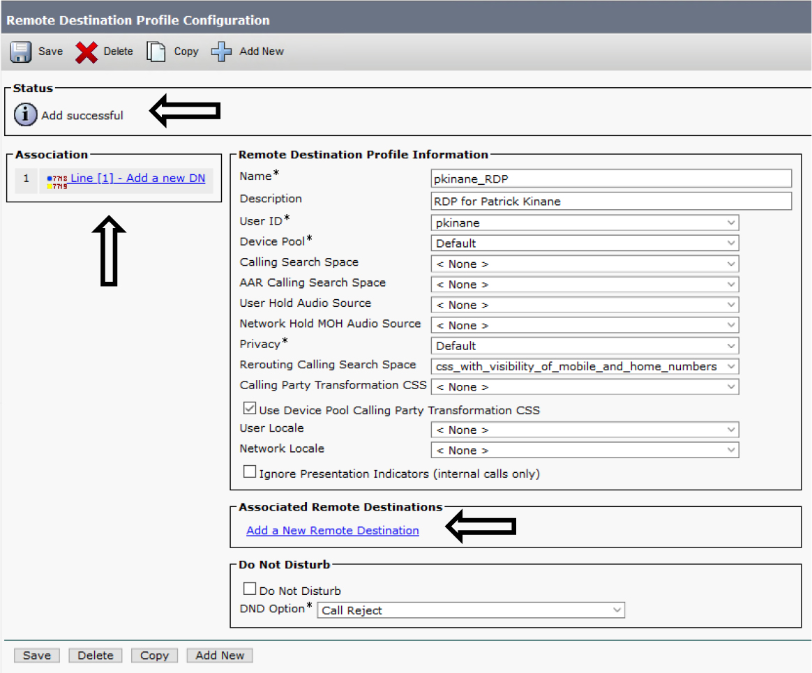
Figure 7-5 RDP Configuration Page After Save
The directory number configured on the RDP must be the same as the directory number configured on the user's desk phone. This means the same number and same partition. Figure 7-6 shows the directory number configured on the user’s Cisco 8865 phone.

Figure 7-6 Directory Number on a Desk Phone
Now that you know the desk phone directory number, you can add the directory number to the RPD by clicking Add a New DN (shown previously in Figure 7-5). The page that appears for configuring the directory number on the RDP looks almost the same as the page for adding a directory number to a phone. While adding the directory number to the RDP, you can modify the line settings that are device specific. Figure 7-7 shows the phone’s device-specific line settings (left) and the RDP’s device-specific line settings (right).
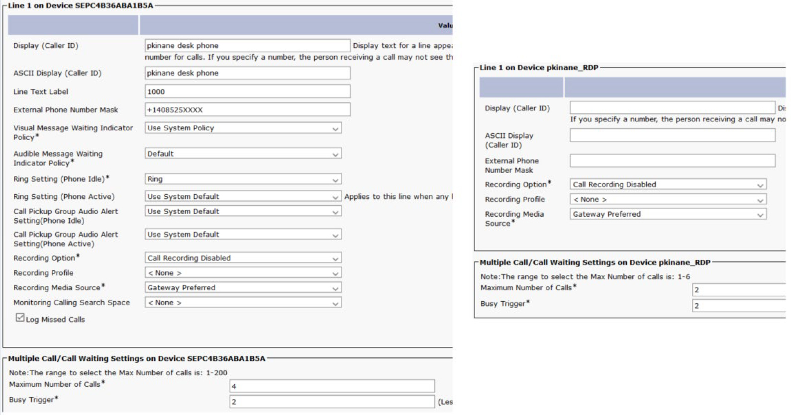
Figure 7-7 Device- and RDP-Specific Line Settings
Step 5. Add a remote destination (mobile phone number or home phone number) to the RDP: Next, you can define the remote destination by clicking on Add a New Remote Destination (shown previously in Figure 7-5). When you add the remote destination, you must give it a name and destination. The destination configured here is the phone number of the remote phone. Figure 7-8 shows the name and destination for the setup used to write this book.
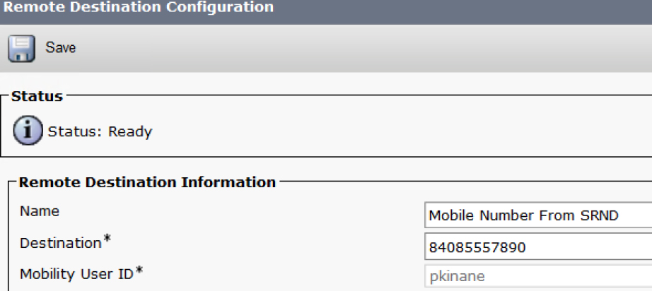
Figure 7-8 Name and Description for a Remote Destination
Depending on the call routing configuration, you may or may not need to define the dial-out number before the remote destination number. In this example, there is an 8 in front of the user’s mobile number (4085557890) because the translation pattern required to route this call starts with an 8. That translation pattern strips the 8 and prefixes +1 to create a +E.164 number for presentation to the service provider. The translation pattern and route pattern configurations are shown in Figure 7-9.
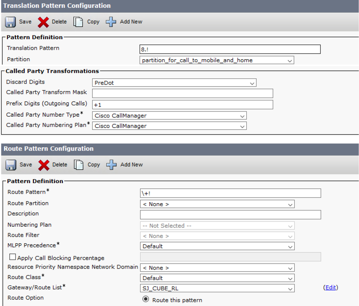
Figure 7-9 Translation and Route Pattern Settings
Step 6. Enable the Line Association Checkbox: When you save the remote destination configuration, the page refreshes to include directory number(s) from the RDP and a checkbox to enable the line association between the remote destination and the directory number(s) as shown in Figure 7-10. By default, this checkbox is not checked; however, it must be checked for the remote destination to ring when a call comes into the RDP’s directory number.

Figure 7-10 Line Association Checkbox
Success! The configuration is complete. Make a test call to the directory number associated with the end-user’s RDP to confirm the work phone and remote destination both ring.
Note
After a directory number and remote destination are configured on the RDP, the directory number page shows a new field titled Associated Remote Destinations. This field displays the remote destination(s) found on the RDP. Something important about this field is that it appears on the directory number page even if nobody puts a check in the Line Association checkbox (shown earlier in Figure 7-10). Do not reference the Associated Remote Destination field on the directory number page to confirm the remote destination has been correctly associated to the line. To be sure the Line Association checkbox is enabled when troubleshooting SNR, navigate to the remote destination page for confirmation. Figure 7-11 and Figure 7-12 show the directory number page before and after the RDP has a directory number and remote destination added.

Figure 7-11 Directory Number Page Before RDP Has a Line and Remote Destination

Figure 7-12 Directory Number Page After RDP Has a Line and Remote Destination
To quickly create a remote destination profile with some configurations pulled from the desk phone, you can select Copy to Remote Destination Profile from the Related Links dropdown, as shown in Figure 7-13.
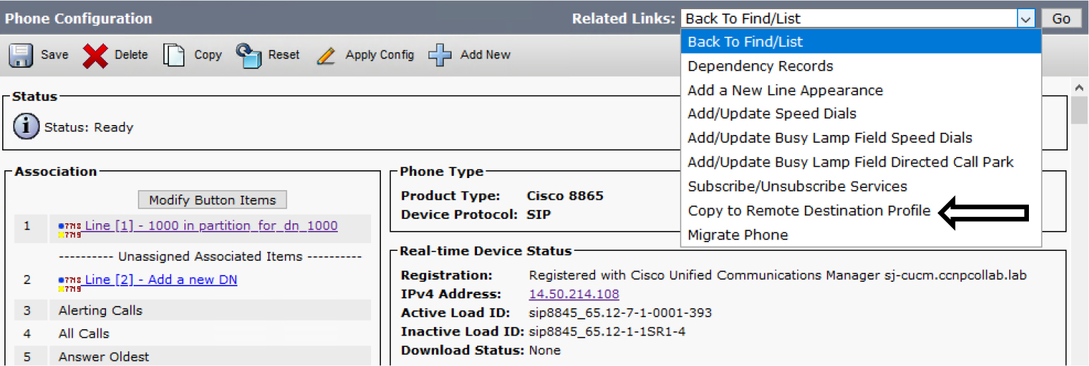
Figure 7-13 Copying a Phone to an RDP
Advanced Single Number Reach Configuration
When using SNR, keep the following in mind:
• Mobile phones may send calls directly to voicemail at times (for example, situations where mobile service is unavailable or the device is powered off).
• Be aware of the time of day users want to receive calls on their mobile phone. For example, a user might not want to receive calls on a remote destination outside business hours or on weekends.
• Some users might want to block a call to the remote destination if the calling party is a specific number.
The next two sections detail how we can handle these situations using more advanced SNR configuration parameters, including SNR Timers, SNR Ring Schedule, and SNR Access Lists. This section also covers other lesser-known advanced SNR topics, such as Inbound Remote Destination Caller ID and Intelligent Session Control.
SNR Timers
This section reviews the timers associated with a remote destination. In Figure 7-14, the first timer listed in the Timer Information box of the Remote Destination Configuration page is called the Delay Before Ringing timer. This timer determines how long Unified CM will wait before extending the call to the remote destination. The Delay Before Ringing timer is measured in seconds and the default value is 4. While you review the CallManager SDL trace logs later in this chapter, you will see when Unified CM performs digit analysis for the remote destination number and how long it waits before sending a SIP INVITE to the remote destination.
The second and third timers, the Answer Too Soon timer and Answer Too Late timer, focus on preventing the remote destination’s voicemail from answering the call. The Answer Too Soon timer determines how long the remote destination should ring before answering the call. This timer can be set to a range of 0 to 10 seconds, with a default of 1.5 seconds. If the remote destination answers the call before the call rings long enough, Unified CM does not allow the call to connect with the remote destination and instead continues ringing the desk phone. This time addresses situations in which a remote destination call is forwarded straight to voicemail rather than ringing.
The Answer Too Late timer is very similar to the Answer Too Soon timer, but it determines when Unified CM should stop ringing the remote destination in order to prevent the remote destination’s voicemail system from answering the call after ringing for a long time. The Answer Too Late timer time is measured in seconds, and valid entries are 0 or a number from 10 to 300. When the Answer Too Soon timer or Answer Too Late timer is set to 0, the timer is disabled.
![]()
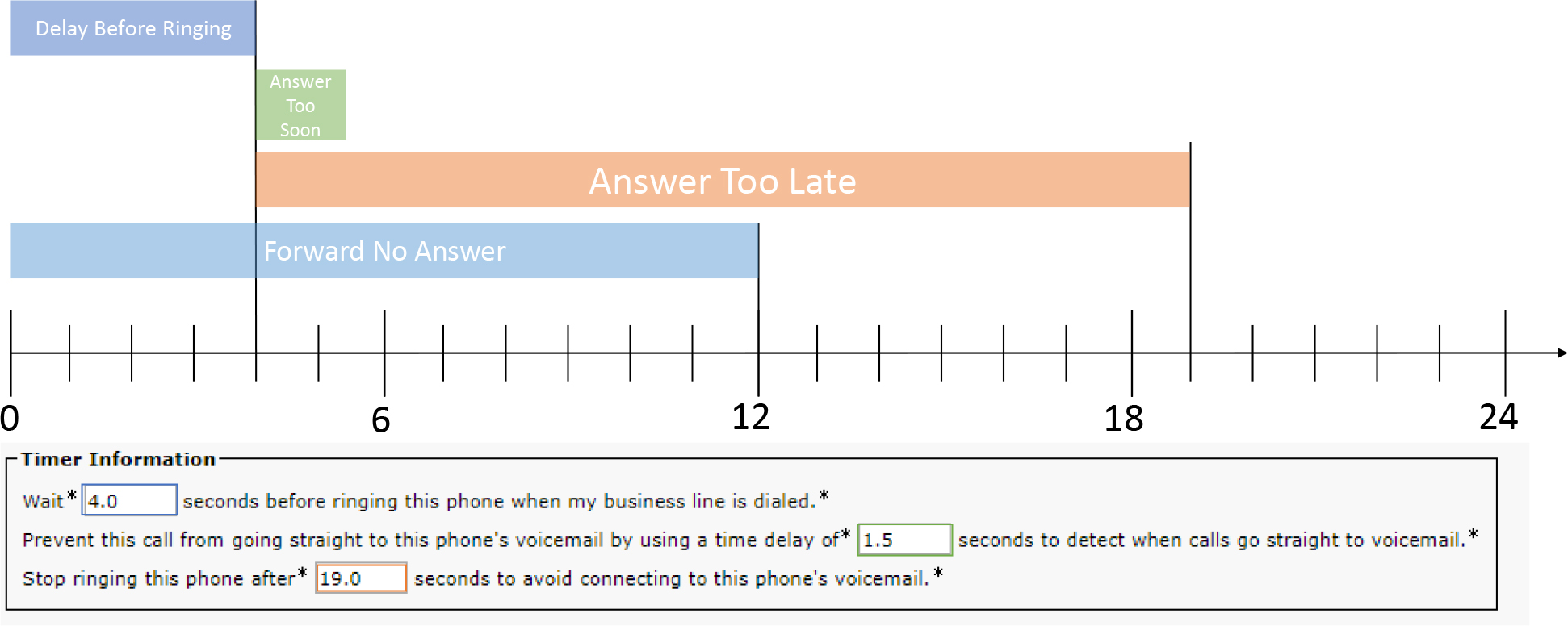
Figure 7-14 Remote Destination Timer Information
Figure 7-14 shows a timeline of these default timers overplayed with a standard U.S. ringing cycle of 6 seconds (2 seconds of ringback with 4 seconds of silence). Note the following in this timeline:
• The Delay Before Ringing timer stops after the configured 4 seconds.
• The Answer Too Soon timer and Answer Too Late timer do not start until the Delay Before Ringing timer ends.
• The Forward No Answer timer references the default No Answer Ring Duration setting configured on the directory number. The default value of 12 seconds is used in this example. When this timer ends, the call is forwarded based on the configured Forward No Answer settings of the directory number. The No Answer Ring Duration timer can be configured on the directory number or left blank to assume the CallManager Service Parameter configuration.
The following are examples of common scenarios observed with SNR timers:
• If the remote destination answers within the Answer Too Soon timer, the call is pulled back from SNR, and the enterprise desk phone continues ringing. This is usually observed when the remote destination voicemail answers without the remote destination phone ringing.
• If the remote destination answers the call before the Answer Too Late timer expires, the enterprise desk phone stops ringing, and the call is connected to the remote destination.
• If the enterprise desk phone answers the call before the Forward No Answer timer ends, the call is connected to the enterprise desk phone and the remote destination stops ringing.
• If the Forward No Answer timer expires, the Ring No Answer configurations redirect the call. To prevent the remote destination’s voicemail from answering the call, the Ring No Answer timer should be less than the amount of time it takes for the remote destination’s voicemail to answer the call.
• If the Answer Too Late timer has ended (assuming that the Forward No Answer timer has not ended first), Unified CM will tell the remote destination to stop ringing (by sending a SIP CANCEL to the remote destination). The enterprise desk phone continues ringing until the Forward No Answer timer expires.
• Sometimes a user may request that the SNR remote destination voicemail answer the call rather than use the Ring No Answer settings of the line. In such a scenario, you can set the Forward No Answer and Answer Too Late timers to a large value; therefore, the remote destination’s voicemail has plenty of time to answer the call before the Forward No Answer and Answer Too Late timers expire.
SNR Ring Schedule
As mentioned earlier, some users might not want their mobile phones ringing at all hours. The Ring Schedule configuration section makes it possible to define times when a remote destination should ring and should not ring. Figure 7-15 shows the default ring schedule settings. You can define the entire day or select a range of time by specifying the start and stop times. The start and stop time inputs are formatted as 24-hour (HH:MM) 15-minute increments.

Figure 7-15 Ring Schedule
SNR Access Lists
Imagine two scenarios that might arise when implementing SNR:
• You might need to restrict specific numbers from reaching the remote destination number when someone calls the desk phone.
• You might want to permit certain calling numbers to reach a remote destination; you want all other calling numbers to ring the desk phone but not the remote destination, essentially disabling the SNR feature for most calls.
Either of these scenarios can be achieved by applying access lists to the remote destination in the configuration page section When Receiving a Call During the Above Ring Schedule. The default configuration is shown in Figure 7-16. Creating access lists is not very intuitive because you must first navigate to Cisco Unified CM Administration > Call Routing > Class of Control > Access List. Once on the access list configuration page, you need to provide a name for the access list and select whether it is for allowing or blocking. After you save the access list, you can add members to it, as shown in Figure 7-17.

Figure 7-16 Applying Access Lists to a Remote Destination

Figure 7-17 Adding Members to an Access List
When adding an access list member, you must provide the filter mask and the directory number mask. The filter mask is dependent on the caller ID of the calling party, and there are three options available:
• Directory Number
• Not Available
• Private
If you choose Directory Number, you need to provide a number, a wildcard, or a combination of the two in the DN Mask field. However, the DN Mask field is grayed out if you chose Not Available or Private because all calls will be caught by the access list when the caller ID is unavailable or marked as private.
The following wildcards are available for the directory number mask:
• X or x to match a single digit
• ! to match any number of digits, either at the beginning or end of the pattern (This character can only be used once in a pattern.)
• # to indicate an exact match for a single digit
After you finish creating an access list, you can navigate to the remote destination and apply the access list to the configuration section shown in Figure 7-16.
Inbound Remote Destination Caller ID and Intelligent Session Control
Consider these two key SNR scenarios:
• Calls placed from the remote destination number to an internal phone number; for example, a call from the user’s mobile number to their co-worker’s desk phone.
• Calls placed from an internal number directly to a remote destination; for example, a call from a co-worker’s desk phone to the user’s mobile number.
When someone places a call from a remote destination to a phone number that is internal, the call comes into the corporate environment and reaches Unified CM. Unified CM extends the call to the called number; however, Unified CM changes the calling party information to reflect the desk phone that is associated with the remote destination rather than showing the remote destination as the calling party. Figure 7-18 illustrates this call flow, which includes the following steps:
![]()
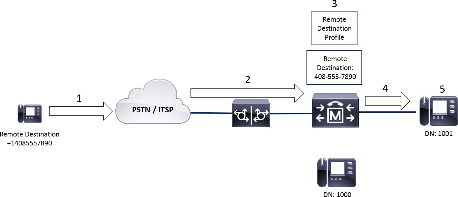
Figure 7-18 Inbound Call from a Remote Destination
Step 1. The remote destination calls 1001’s full number to reach the internal phone from outside the network.
Step 2. The call enters the network and is sent to Unified CM.
Step 3. Unified CM notices that the calling party, +1-408-555-7890, matches a remote destination.
Step 4. Unified CM extends the call to 1001 as if it is from the desk phone at 1000.
Step 5. The phone at 1001 displays caller ID that reflects the desk phone at 1000.
Note
The phone with DN 1000 is not engaged in the call, but extension 1000 on the desk phone shows as a shared line in use remotely. This is because the line on the RDP is a shared line.
Two service parameters affect this inbound calling party matching: Matching Caller ID with Remote Destination and Number of Digits for Caller ID Partial Match (see Figure 7-19). You can find them by navigating to Cisco Unified CM Administration > System > Service Parameters > Server > Cisco CallManager. The options for Matching Caller ID with Remote Destination are Complete Match and Partial Match. When this parameter is set to Partial Match, you can specify how many digits must match by modifying the service parameter Number of Digits for Caller ID Partial Match. When using partial match with a requirement to match 7 digits, the last seven digits are considered. For example, when the calling party is +1-408-555-7890, the digits 555-7890 must match a remote destination. The minimum number of digits allowed for this parameter is 3, and the maximum is 24.

Figure 7-19 Inbound Calling Party Match Service Parameters
In the scenario in which someone places a call from within the internal network to a remote destination, Unified CM can route the call to the desk phone rather than to the remote destination. This is known as Intelligent Session Control. To use Intelligent Session Control, you must navigate to Cisco Unified CM Administration > System > Service Parameters > Server > Cisco CallManager. Then, in the service parameter configuration, you locate the section Clusterwide Parameters (Feature - Reroute Remote Destination Calls to Enterprise Number). Figure 7-20 shows this section, which includes the parameter Reroute Remote Destination Calls to Enterprise Number.

Figure 7-20 Reroute Remote Destination Calls to Enterprise Number Service Parameter
When Reroute Remote Destination Calls to Enterprise Number is set to True, Unified CM routes calls to the desk phone rather than to the remote destination. As with most other settings, it is advisable to restart the phone after a configuration change to ensure the phone is updated with the latest information from Unified CM. Figure 7-21 shows a call flow using Intelligent Session Control:
![]()
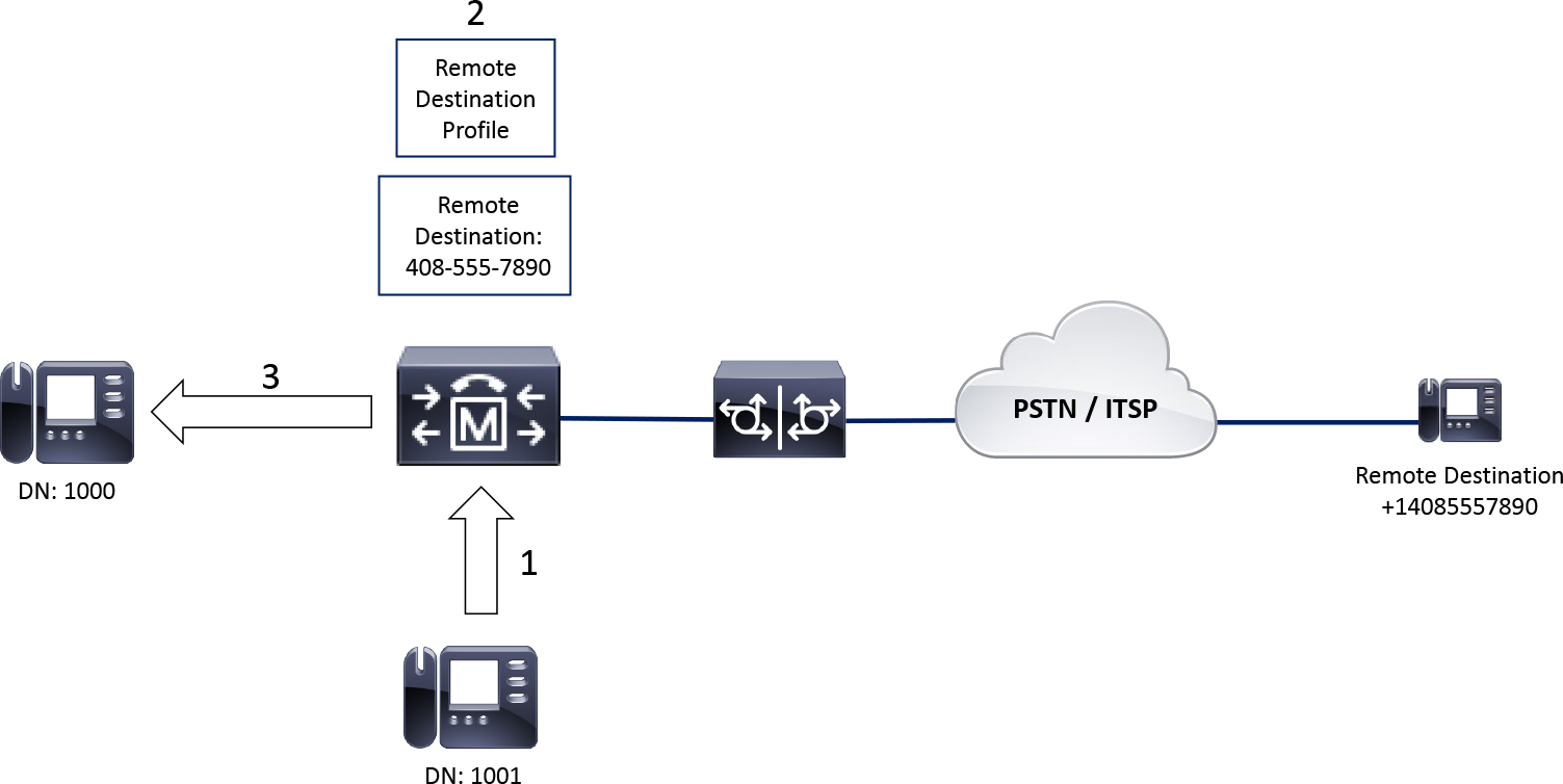
Figure 7-21 Intelligent Session Control Call Flow
Step 1. The user at 1001 calls the remote destination (+14085557890).
Step 2. Unified CM notices the called party +14085557890 matches a remote destination; furthermore, the remote destination is associated with the internal directory number 1000.
Step 3. Unified CM routes the call to the desk phone at 1000 instead of the remote destination.
Note
Intelligent Session Control is considered a security concern because someone can use this feature to intercept calls meant for another person and redirect them.
Troubleshoot Single Number Reach
After configuring SNR, you can verify the feature is working by placing a test call to the desk phone and seeing if the remote destination rings. It is important to wait long enough for the timers when testing SNR as the call is only extended to the remote destination after the Delay Before Ringing time is met.
Note
When troubleshooting SNR, it is important to keep in mind the sequence of events shown earlier in this chapter in Figure 7-1.
Consider the following recommendations when troubleshooting SNR:
• Validate the configuration using the steps and screenshots from the previous section as a reference.
• Place a test call to reproduce the issue and then collect CallManager SDL trace logs for analysis, as described in this section.
The following mistakes commonly occur with SNR configurations:
• No Rerouting Calling Search Space is applied to the RDP.
• The Line Association checkbox is not selected on the RDP.
• The remote destination does not match a pattern for routing the call.
• Enable Mobility is not selected on the end-user configuration page.
Figure 7-22 illustrates a sample call flow where a call is answered at the remote destination. Notice that when the user hangs up the mobile phone, the calling party is put on hold because the Desk Pickup feature is enabled.
Note
Remember when a user hangs up their mobile phone and resumes the call on their desk phone, this is called Desk Pickup. If the calling party hangs up, the call terminates completely. The ability to transition between devices applies only when the called party (the remote destination) hangs up and the calling party waits for the end user to resume the call on their desk phone.

Figure 7-22 SNR Sample Call Flow
You can collect CallManager SDL trace logs from Unified CM to confirm the system is routing calls properly. Example 7-1 through Example 7-10 detail the following steps, which relate to Figure 7-22.
Note
A lot of text has been removed from the SIP messages and other parts of the log snippets throughout this chapter. This was done for brevity and to focus on the important sections of the logs.
Step 1. Unified CM receives a SIP INVITE from IP Phone A (1001) with the called party being IP Phone B (directory number 1000). Unified CM performs digit analysis on the called number to locate a callable device (see Example 7-1).
Note
For more information about the digit analysis process, refer to Chapter 4.
Example 7-1 CallManager SDL Trace Analysis for SNR, Snippet 1
04827703.002 |15:37:30.842 |AppInfo  |SIPTcp - wait_SdlReadRsp: Incoming SIP TCP message from 14.50.214.106 on port 50322 index 20687 with 2962 bytes:
[606276,NET]
INVITE sip:[email protected];user=phone SIP/2.0
Via: SIP/2.0/TCP 14.50.214.106:50322;branch=z9hG4bK3381acac
From: “1001" <sip:[email protected]>;tag=d0ec35ffebc4041c57238fa0-47656c2c
To: <sip:1000@sj-cucm.ccnpcollab.lab>
Call-ID: [email protected]
CSeq: 101 INVITE
Contact: <sip:[email protected]:50322;transport=tcp>;+u.sip!devicename.ccm.cisco.com="SEPD0EC35FFEBC4";video
Remote-Party-ID: “1001” <sip:[email protected]>;party=calling;id-type=subscriber;privacy=off;screen=yes
Content-Type: application/sdp
Content-Disposition: session;handling=optional

o=Cisco-SIPUA 11557 0 IN IP4 14.50.214.106
m=audio 16598 RTP/AVP 114 9 124 113 115 0 8 116 18 101
c=IN IP4 14.50.214.106
a=sendrecv

04827733.007 |15:37:31.027 |AppInfo  |Digit analysis: match(pi="2", fqcn="+14085251001", cn="1001",plv="5", pss="partition_for_dn_1000", TodFilteredPss="partition_for_dn_1000", dd="1000",dac="1")
04827733.008 |15:37:31.028 |AppInfo  |Digit analysis: analysis results
04827733.009 |15:37:31.028 |AppInfo  ||PretransformCallingPartyNumber=1001
|CallingPartyNumber=1001
|DialingPartition=partition_for_dn_1000
|DialingPattern=1000
|FullyQualifiedCalledPartyNumber=1000
|DialingPatternRegularExpression=(1000)
|RouteBlockFlag=RouteThisPattern
Step 2. Unified CM finds two callable devices: the IP phone SEPC4B36ABA1B5A associated to the line and the remote destination profile (RDP) pkinane_RDP associated with the line. Notice the trace logs shown in Example 7-2, this is in the format remotedestination_rdpname. This helps find where the RDP is engaged in the trace logs.
Example 7-2 CallManager SDL Trace Analysis for SNR, Snippet 2
04827752.001 |15:37:31.042 |AppInfo  |LineCdpc(39): -dispatchToAllDevices-, sigName=CcSetupReq, device=84085557890_pkinane_RDP
04827752.002 |15:37:31.042 |AppInfo  |LineCdpc(39): -dispatchToAllDevices-, sigName=CcSetupReq, device=SEPC4B36ABA1B5A
Step 3. Unified CM checks the time zone, date, and day of the week then looks for any active access lists to determine if the call should move forward as displayed in Example 7-3. In this scenario, IP Phone A is permitted to call the remote destination. Note that the DayOfWeek value is a number rather than a name. The call occurred on a Friday, and thus number 5 (the week starts on Sunday, which has the value 0). Unified CM also prints the remote destination dump (RemDest dump), which includes the value of the Delay Before Ringing Timer; however, the value is listed here in milliseconds.
Example 7-3 CallManager SDL Trace Analysis for SNR, Snippet 3
04827753.004 |15:37:31.049 |AppInfo  |TODAccessHelper - isTODAccessAllowed: found todPkid = 7ac14ce7-93d6-6081-d2c6-0efdc15a32de, timezone = 22 for remdest [84085557890]
04827753.005 |15:37:31.049 |AppInfo  |TODAccessHelper - isTODAccessAllowed: checking against time = 1/17/120 15:37:31 DayOfWeek [5]
04827753.006 |15:37:31.049 |AppInfo  |TODAccessHelper - isTODAccessAllowed: no active access list is found, call is allowed for given cpgn
04827753.007 |15:37:31.050 |AppInfo  |SNRD::wait_CcSetupReq    (0000011) Caller[1001] is allowed to call [84085557890]

04827754.006 |15:37:31.060 |AppInfo  |DbMobility - RemDest dump: cnumber = 84085557890, devicePkid = 6cc74fac-d7c2-77ab-e416-55919bd9e131, remDestProfilePkidStr = 08efe167-69c1-0bf4-8bee-778a2eeab494, isMobilePhone = 1, isDualMode = 0, isSmartPhone = 0, isSNREnabled= 1, answerTooSoonTimer = 1500, answerTooLateTimer = 19000, delayBeforeRingingCellTimer = 4000, userId = pkinane, timeZoneIndex = 0, requireThirdPartyRegistration = 0, blockIncomingCallsWhenRoaming = 0, homeNetworkID = , description = Mobile Number From SRND, url = , SNRVMAvoidancePolicy = 0, DvorVMAPolicy = 0
Step 4. Unified CM performs a digit analysis for the remote destination number +14085557890 (see Example 7-4). Note that a translation occurs, and it is not visible in the trace logs. This translation modifies 84085557890 into the globalized +E.164 format (+14085557890). Also notice that the digit analysis occurs before any of the SNR timers mentioned previously in the chapter.
Example 7-4 CallManager SDL Trace Analysis for SNR, Snippet 4
04827765.010 |15:37:31.090 |AppInfo  |Digit analysis: match(pi="2", fqcn="+14085251001", cn="1001",plv="5", pss="partition_for_call_to_mobile_and_home", TodFilteredPss="partition_for_call_to_mobile_and_home", dd="84085557890",dac="1")
04827765.011 |15:37:31.091 |AppInfo  |Digit analysis: analysis results
04827765.012 |15:37:31.091 |AppInfo  ||PretransformCallingPartyNumber=+14085251001
|CallingPartyNumber=+14085251001
|DialingPartition=
|DialingPattern=+!
|FullyQualifiedCalledPartyNumber=+14085557890
|DialingPatternRegularExpression=(+[0-9]+)
|RouteBlockFlag=RouteThisPattern
Step 5. Unified CM extends the call to IP Phone B. The signaling and logs from this call leg are truncated in Example 7-5 to focus on the aspects of SNR in the trace logs.
Example 7-5 CallManager SDL Trace Analysis for SNR, Snippet 5
04827823.001 |15:37:31.163 |AppInfo  |SIPTcp - wait_SdlSPISignal: Outgoing SIP TCP message to 14.50.214.108 on port 51621 index 20489
[606281,NET]
INVITE sip:[email protected]:51621;transport=tcp SIP/2.0
Via: SIP/2.0/TCP 172.18.110.61:5060;branch=z9hG4bK46f96487a292
From: <sip:1001@172.18.110.61>;tag=313455~bbab2af3-f2b4-4a8c-a020-a2cc3e6cebe7-20545485
To: <sip:[email protected]>
Call-ID: [email protected]
CSeq: 101 INVITE
Remote-Party-ID: <sip:[email protected];x-cisco-callback-number=1001>;party=calling;screen=yes;privacy=off
Step 6. After 4 seconds of ringing IP Phone B, the SdlTimerService sends a notification that the 4 second Delay Before Ringing timer has expired. Then Unified CM sends SJ CUBE an INVITE message to call the remote destination at +14085557890 (see Example 7-6). Remember this was decided in step 4 during the digit analysis action. Here you can also confirm that the remote destination answers the call, as indicated by the 200 OK message received from CUBE. The call sent to IP Phone B is terminated with a SIP CANCEL message, which is not shown in the trace snippets in this chapter (although it is present in the trace logs collected from Unified CM).
Example 7-6 CallManager SDL Trace Analysis for SNR, Snippet 6
04827855.000 |15:37:35.107 |SdlSig   |DelayBeforeRingTimer                   |delayBeforeRing                |CellProxyCdpc(1,100,40,19)       |SdlTimerService(1,100,3,1)       |1,100,251,760.606^14.50.214.106^SEPD0EC35FFEBC4 |[R:H-H:0,N:0,L:0,V:0,Z:0,D:0]

04827902.001 |15:37:35.215 |AppInfo  |SIPTcp - wait_SdlSPISignal: Outgoing SIP TCP message to 172.18.110.62 on port 5060 index 21615
[606284,NET]
INVITE sip:[email protected]:5060 SIP/2.0
Via: SIP/2.0/TCP 172.18.110.61:5060;branch=z9hG4bK46f971b12b3ed
From: <sip:+14085251001@172.18.110.61>;tag=313456~bbab2af3-f2b4-4a8c-a020-a2cc3e6cebe7-20545485
To: <sip:[email protected]>
Call-ID: [email protected]
CSeq: 101 INVITE
P-Asserted-Identity: <sip:[email protected]>
Remote-Party-ID: <sip:[email protected]>;party=calling;screen=yes;privacy=off
Contact: <sip:[email protected]:5060;transport=tcp>;video;audio;+u.sip!devicename.ccm.cisco.com="SEPD0EC35FFEBC4"

04827963.002 |15:37:43.728 |AppInfo  |SIPTcp - wait_SdlReadRsp: Incoming SIP TCP message from 172.18.110.62 on port 5060 index 21615 with 1135 bytes:
[606292,NET]
SIP/2.0 200 OK
Via: SIP/2.0/TCP 172.18.110.61:5060;branch=z9hG4bK46f971b12b3ed
From: <sip:+14085251001@172.18.110.61>;tag=313456~bbab2af3-f2b4-4a8c-a020-a2cc3e6cebe7-20545485
To: <sip:[email protected]>;tag=B7CEC149-2237
Call-ID: [email protected]
CSeq: 101 INVITE
Contact: <sip:[email protected]:5060;transport=tcp>
Server: Cisco-SIPGateway/IOS-16.12.1a
Content-Type: application/sdp

o=CiscoSystemsSIP-GW-UserAgent 9198 1184 IN IP4 172.18.110.62
c=IN IP4 172.18.110.62
m=audio 8094 RTP/AVP 0 19
c=IN IP4 172.18.110.62
Step 7. The call remains active until one of the endpoints hangs up. In Example 7-7, the remote destination hangs up, and Unified CM receives a SIP BYE message to end the call with the mobile phone; however, the call is not completely done yet.
Example 7-7 CallManager SDL Trace Analysis for SNR, Snippet 7
04828241.003 |15:37:56.436 |AppInfo  |SIPTcp - wait_SdlReadRsp: Incoming SIP TCP message from 172.18.110.62 on port 13030 index 21616 with 598 bytes:
[606308,NET]
BYE sip:[email protected]:5060;transport=tcp SIP/2.0
Via: SIP/2.0/TCP 172.18.110.62:5060;branch=z9hG4bK1A423B7
From: <sip:[email protected]>;tag=B7CEC149-2237
To: <sip:[email protected]>;tag=313456~bbab2af3-f2b4-4a8c-a020-a2cc3e6cebe7-20545485
Call-ID: [email protected]
CSeq: 101 BYE
Reason: Q.850;cause=16
Step 8. Instead of completely disconnecting the call with IP Phone A, Unified CM places IP Phone A on hold. Before IP Phone A can be placed on hold, A SIP re-INVITE message is sent from Unified CM to IP Phone A tearing down the media as shown in Example 7-8. Note the quad-zero connection IP address (0.0.0.0) and a=inactive, indicating the media is being torn down. Hold concepts and resume concepts are discussed in detail in Chapter 9, “CUBE Interworking Features.”
Example 7-8 CallManager SDL Trace Analysis for SNR, Snippet 8
04828249.000 |15:37:56.441 |SdlSig   |CcHoldInd                              |restart0                       |LineControl(1,100,85,14)         |CellProxyCdpc(1,100,40,19)       |1,100,251,766.2^172.18.110.62^*          |[R:N-H:0,N:0,L:0,V:0,Z:0,D:0] CI=20545485 CI.branch=16777235  StreamId=

04828274.001 |15:37:56.444 |AppInfo  |SIPTcp - wait_SdlSPISignal: Outgoing SIP TCP message to 14.50.214.106 on port 50322 index 20687
[606309,NET]
INVITE sip:[email protected]:50322;transport=tcp SIP/2.0
Via: SIP/2.0/TCP 172.18.110.61:5060;branch=z9hG4bK46f9d5fcc36e5
From: <sip:[email protected]>;tag=313453~bbab2af3-f2b4-4a8c-a020-a2cc3e6cebe7-20545484
To: “1001” <sip:[email protected]>;tag=d0ec35ffebc4041c57238fa0-47656c2c
Call-ID: [email protected]
CSeq: 102 INVITE
Remote-Party-ID: <sip:[email protected]>;party=calling;screen=yes;privacy=off
Contact: <sip:[email protected]:5060;transport=tcp>
Content-Type: application/sdp

o=CiscoSystemsCCM-SIP 313453 2 IN IP4 172.18.110.61
c=IN IP4 0.0.0.0
m=audio 8094 RTP/AVP 0
a=inactive
Step 9. IP Phone B is provided the option to use the Desk Pickup feature when Unified CM sends a SIP NOTIFY message to IP Phone B (see Example 7-9). This NOTIFY message lets the phone know there is a call available for the Desk Pickup feature.
Example 7-9 CallManager SDL Trace Analysis for SNR, Snippet 9
04828338.001 |15:37:56.573 |AppInfo  |SIPTcp - wait_SdlSPISignal: Outgoing SIP TCP message to 14.50.214.108 on port 51621 index 20489
[606313,NET]
NOTIFY sip:[email protected]:51621;transport=tcp SIP/2.0
Via: SIP/2.0/TCP 172.18.110.61:5060;branch=z9hG4bK46f9fe785ed8
From: <sip:172.18.110.61>;tag=1610814960
To: <sip:[email protected]>
Call-ID: [email protected]
CSeq: 101 NOTIFY
Max-Forwards: 70
Date: Fri, 17 Jan 2020 20:37:56 GMT
User-Agent: Cisco-CUCM12.5
Event: dialog
Subscription-State: active
Contact: <sip:172.18.110.61:5060;transport=tcp>
Content-Type: application/dialog-info+xml
Content-Length: 971

<dialog-info xmlns="urn:ietf:parmams:xml:ns:dialog-info"
 xmlns:call="urn:x-cisco:parmams:xml:ns:dialog-info:dialog:callinfo-dialog"
 xmlns:xsi="http://www.w3.org/2001/XMLSchema-instance"
 version="8” state="partial” entity="sip:[email protected]">
  <dialog id="39” call-id="[email protected]” local-tag="bbab2af3-f2b4-4a8c-a020-a2cc3e6cebe7-20545485” remote-tag="bbab2af3-f2b4-4a8c-a020-a2cc3e6cebe7-20545485” direction="recipient">
    <state>confirmed</state>
    <call:instance>1</call:instance>
    <call:orientation>From</call:orientation>
    <call:lock>unlocked</call:lock>
    <duration>25</duration>
    <call:gci>1-6020</call:gci>
    <local>
      <identity display="">sip:[email protected]:5060</identity>
      <target uri="sip:[email protected]:5060">
        <param pname="+sip.rendering” pval="no"/>
      </target>
    </local>
    <remote>
      <identity display="">sip:1001@172.18.110.61:5060</identity>
    </remote>
  </dialog>
</dialog-info>
Step 10. IP Phone B sends Unified CM an INVITE message, and then Unified CM sends the phone a 200 OK message in response (see Example 7-10). Although the example does not show it, Unified CM sends a re-INVITE message to IP Phone A to take IP Phone A off hold and connect IP Phone A with IP Phone B.
Example 7-10 CallManager SDL Trace Analysis for SNR, Snippet 10
04828397.002 |15:37:58.414 |AppInfo  |SIPTcp - wait_SdlReadRsp: Incoming SIP TCP message from 14.50.214.108 on port 51621 index 20489 with 3125 bytes:
[606316,NET]
INVITE sip:[email protected];user=phone SIP/2.0
Via: SIP/2.0/TCP 14.50.214.108:51621;branch=z9hG4bK23819e86
From: “pkinane desk phone” <sip:[email protected]>;tag=c4b36aba1b5a027b16a55a5c-3a3c09cd
To: <sip:[email protected]>
Call-ID: [email protected]
CSeq: 101 INVITE
Contact: <sip:[email protected]:51621;transport=tcp>;+u.sip!devicename.ccm.cisco.com="SEPC4B36ABA1B5A";video
Replaces: [email protected];to-tag=bbab2af3-f2b4-4a8c-a020-a2cc3e6cebe7-20545485;from-tag=bbab2af3-f2b4-4a8c-a020-a2cc3e6cebe7-20545485
Remote-Party-ID: “pkinane desk phone” <sip:[email protected]>;party=calling;id-type=subscriber;privacy=off;screen=yes
Content-Type: application/sdp

o=Cisco-SIPUA 23364 0 IN IP4 14.50.214.108
m=audio 25846 RTP/AVP 114 9 124 113 115 0 8 116 18 101
c=IN IP4 14.50.214.108
a=sendrecv

04828562.001 |15:37:58.541 |AppInfo  |SIPTcp - wait_SdlSPISignal: Outgoing SIP TCP message to 14.50.214.108 on port 51621 index 20489
[606325,NET]
SIP/2.0 200 OK
Via: SIP/2.0/TCP 14.50.214.108:51621;branch=z9hG4bK23819e86
From: “pkinane desk phone” <sip:[email protected]>;tag=c4b36aba1b5a027b16a55a5c-3a3c09cd
To: <sip:[email protected]>;tag=313464~bbab2af3-f2b4-4a8c-a020-a2cc3e6cebe7-20545485
Call-ID: [email protected]
CSeq: 101 INVITE
Remote-Party-ID: <sip:[email protected]>;party=called;screen=yes;privacy=off
Contact: <sip:[email protected]:5060;transport=tcp>;+u.sip!devicename.ccm.cisco.com="SEPD0EC35FFEBC4";video
Content-Type: application/sdp

o=CiscoSystemsCCM-SIP 313464 1 IN IP4 172.18.110.61
c=IN IP4 14.50.214.106
m=audio 16598 RTP/AVP 114 101
Example 7-11 shows the CallManager trace logs related to the SNR timers for two calls. Using these trace snippets as a point of reference, you can see what is occurring with the SNR timers, such as the Call Forward No Answer of the Line, SNR Delay Before SNR Ringing, SNR Answer Too Soon, and SNR Answer Too Late timers. The first test call illustrates the 4-second Delay Before Ringing timer and then the Answer Too Soon timer. This call was never answered, so the IP phone’s Call Forward No Answer timer canceled the call to all devices after 12 seconds of ringing.
The second test call still uses the default SNR timers, but the Forward No Answer timer on the line has been changed from the default value to 36 seconds. Since this timer is larger than the SNR Delay Before Ringing and SNR Answer Too Late timers, the remote destination stops ringing before the IP Phone stops ringing. Twenty-three seconds into the call (Delay Before Ringing [4] + Answer Too Late [19] = 23), you can see the remote destination call is cancelled. At the 36-second mark, the Forward No Answer timer expires, and that call is canceled.
Example 7-11 Default SNR Timers in the Trace Logs
### Test Call 1, default Unified CM Timers
### Default SNR Timers are set
00392292.006 |11:17:03.061 |AppInfo |DbMobility - RemDest dump: cnumber = 5555, devicePkid = a379e10f-7d80-f405-3ecd-1a675206e1e4, remDestProfilePkidStr = 70690b51-30c9-58e8-4bab-0c9140a9fc35, isMobilePhone = 1, isDualMode = 0, isSmartPhone = 0, isSNREnabled= 1, answerTooSoonTimer = 1500, answerTooLateTimer = 19000, delayBeforeRingingCellTimer = 4000, userId = SNR_USER, timeZoneIndex = 0, requireThirdPartyRegistration = 0, blockIncomingCallsWhenRoaming = 0, homeNetworkID = , description = TEST_RD, url = , SNRVMAvoidancePolicy = 0, DvorVMAPolicy = 0
### Unified CM sets the Call Forward No Answer timer and sends an INVITE to the IP Phone
00392320.002 |11:17:03.062 |AppInfo  |Forwarding - startCFNATimer (12000) for line entry 1008 - callKey= 0x7

00392344.001 |11:17:03.064 |AppInfo  |SIPTcp - wait_SdlSPISignal: Outgoing SIP TCP message to 14.50.214.122 on port 50761 index 407
INVITE sip:[email protected]:50761;transport=tcp SIP/2.0
### 4 seconds later, the Delay Before Ringing timer ends and Unified CM extends the call to SNR RD
00392374.000 |11:17:07.073 |SdlSig   |DelayBeforeRingTimer                   |delayBeforeRing                |CellProxyCdpc(1,100,40,8)        |SdlTimerService(1,100,3,1)       |1,100,251,10.1587^14.50.214.100^SEPF8A5C59E0F52 |[R:H-H:1,N:0,L:0,V:0,Z:0,D:0]

00392393.001 |11:17:07.076 |AppInfo  |SIPTcp - wait_SdlSPISignal: Outgoing SIP TCP message to 172.18.110.65 on port 5060 index 413
INVITE sip:[email protected]:5060 SIP/2.0
### Answer Too Soon Timer Ends
00392415.000 |11:17:08.577 |SdlSig |Answer2SoonTimer |active |CellProxyCdpc(1,100,40,8) |SdlTimerService(1,100,3,1) |1,100,251,10.1587^14.50.214.100^SEPF8A5C59E0F52 |[R:H-H:0,N:0,L:0,V:0,Z:0,D:0]
### The Call Forward No Answer ends at 12 seconds and Unified CM sends a SIP CANCEL all devices
00392425.000 |11:17:15.066 |SdlSig   |ForwardNoAnswerTimer                   |awaitingCallResponse           |Forwarding(1,100,60,7)           |SdlTimerService(1,100,3,1)       |1,100,251,10.1587^14.50.214.100^SEPF8A5C59E0F52 |[R:H-H:0,N:0,L:0,V:0,Z:0,D:0]
00392466.001 |11:17:15.067 |AppInfo  |SIPTcp - wait_SdlSPISignal: Outgoing SIP TCP message to 14.50.214.122 on port 50761 index 407
CANCEL sip:[email protected]:50761;transport=tcp SIP/2.0

00392468.001 |11:17:15.067 |AppInfo  |SIPTcp - wait_SdlSPISignal: Outgoing SIP TCP message to 172.18.110.65 on port 5060 index 413
CANCEL sip:[email protected]:5060 SIP/2.0

-------------------------------------------------------------------
### Test Call 2, default SNR Timers but 36 second Call Forward No Answer Timer
### Default SNR Timers are set
00393260.006 |11:20:05.226 |AppInfo |DbMobility - RemDest dump: cnumber = 5555, devicePkid = a379e10f-7d80-f405-3ecd-1a675206e1e4, remDestProfilePkidStr = 70690b51-30c9-58e8-4bab-0c9140a9fc35, isMobilePhone = 1, isDualMode = 0, isSmartPhone = 0, isSNREnabled= 1, answerTooSoonTimer = 1500, answerTooLateTimer = 19000, delayBeforeRingingCellTimer = 4000, userId = SNR_USER, timeZoneIndex = 0, requireThirdPartyRegistration = 0, blockIncomingCallsWhenRoaming = 0, homeNetworkID = , description = TEST_RD, url = , SNRVMAvoidancePolicy = 0, DvorVMAPolicy = 0
### Unified CM sets the Call Forward No Answer timer and sends an INVITE to the IP Phone
00393288.002 |11:20:05.228 |AppInfo  |Forwarding - startCFNATimer (36000) for line entry 1008 - callKey= 0x8
00393311.001 |11:20:05.229 |AppInfo  |SIPTcp - wait_SdlSPISignal: Outgoing SIP TCP message to 14.50.214.122 on port 50761 index 407
INVITE sip:[email protected]:50761;transport=tcp SIP/2.0
### 4 seconds later, the Delay Before Ringing timer ends and Unified CM extends the call to SNR RD
00393343.000 |11:20:09.241 |SdlSig   |DelayBeforeRingTimer                   |delayBeforeRing                |CellProxyCdpc(1,100,40,9)        |SdlTimerService(1,100,3,1)       |1,100,251,10.1597^14.50.214.100^SEPF8A5C59E0F52 |[R:H-H:0,N:0,L:0,V:0,Z:0,D:0]
00393365.001 |11:20:09.244 |AppInfo  |SIPTcp - wait_SdlSPISignal: Outgoing SIP TCP message to 172.18.110.65 on port 5060 index 413
INVITE sip:[email protected]:5060 SIP/2.0
### After 19 seconds the SNR Answer Too Late Timer expires and the call to the SNR RD is cancelled. Total time of the call so far is 23 seconds.
00393423.000 |11:20:28.248 |SdlSig   |AnswerTooLateTimer                     |active                         |CellProxyCdpc(1,100,40,9)        |SdlTimerService(1,100,3,1)       |1,100,251,10.1597^14.50.214.100^SEPF8A5C59E0F52 |[R:H-H:0,N:0,L:0,V:0,Z:0,D:0]
00393427.001 |11:20:28.249 |AppInfo  |SIPTcp - wait_SdlSPISignal: Outgoing SIP TCP message to 172.18.110.65 on port 5060 index 413
CANCEL sip:[email protected]:5060 SIP/2.0
### The Call Forward No Answer ends at 36 seconds and Unified CM sends a SIP CANCEL to the IP Phone
00393468.000 |11:20:41.242 |SdlSig   |ForwardNoAnswerTimer                   |awaitingCallResponse           |Forwarding(1,100,60,8)           |SdlTimerService(1,100,3,1)       |1,100,251,10.1597^14.50.214.100^SEPF8A5C59E0F52 |[R:H-H:1,N:0,L:0,V:0,Z:0,D:0]
00393505.001 |11:20:41.243 |AppInfo  |SIPTcp - wait_SdlSPISignal: Outgoing SIP TCP message to 14.50.214.122 on port 50761 index 407
CANCEL sip:[email protected]:50761;transport=tcp SIP/2.0
Configure and Verify Move to Mobile
Imagine that you are engaged in an important conference call on your enterprise desk phone, but you need to step out of the office. Normally you would need to disconnect from the desk phone and rejoin the call from your mobile phone; however, the Move to Mobile feature allows users to transition the call from the desk phone to the mobile phone through a simple button press. It is essentially the reverse of Desk Pickup, described earlier.
The Move to Mobile feature is closely related to SNR, and configuring this feature involves the same configuration as SNR; however, you do not need to check the SNR box on the Remote Destination Configuration page in order for Move to Mobile to work (see Figure 7-23). However, many organizations have Move to Mobile and Single Number Reach configured at the same time, and in such scenarios, both the SNR checkbox and Move to Mobile checkbox are checked.
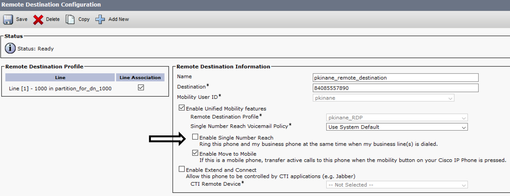
Figure 7-23 Move to Mobile Does Not Require SNR
When you have finished configuring Move to Mobile, you need to add the Mobility softkey to the phone. To add the softkey, navigate to Cisco Unified CM Administration > Device > Device Settings > Softkey Template. At this point, you can add the softkey to an existing template or create a new one. This section shows how to create a new template named Mobility_User. To create a new template, on the Softkey Template page, click Add New then, as shown in Figure 7-24, select the template you want to use as a basis for your new template (for example, Standard User).

Figure 7-24 Copying the Standard User Template
When your new template is saved to the system, make sure Related Links is set to Configure Softkey Layout, as shown in Figure 7-25, and click Go.

Figure 7-25 Configuring the Softkey Layout
Two call states include the Mobility softkey: On Hook and Connected. To use Move to Mobile, the Mobility softkey must be added to the Connected call state, as shown in Figure 7-26 and Figure 7-27.
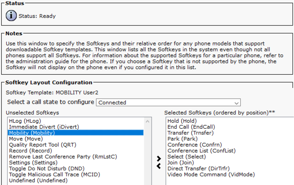
Figure 7-26 Connected Call State Without the Mobility Softkey
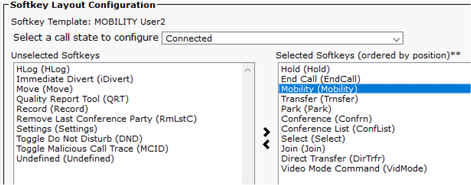
Figure 7-27 Connected Call State with the Mobility Softkey
When the new template is added to the phone, and the phone is connected to a call, you should see the Mobility option on the phone, as shown at the bottom of Figure 7-28.
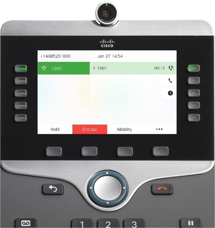
Figure 7-28 Connected Call Showing the Mobility Softkey
When the Mobility softkey is clicked, the user is prompted to make a selection, as shown in Figure 7-29. If the user chooses to send the call to a mobile phone, the desk phone returns to the connected call while waiting for the mobile phone to answer.

Figure 7-29 Mobility Selection
Note
The Mobility softkey has two functions. If the Mobility softkey is added to the On Hook call state, it can be used to enable/disable SNR; however, the phone screen says Mobile Connect because SNR was formerly known as Mobile Connect. If SNR is disabled, and the Mobility softkey is added to the On Hook call state, the user can enable SNR by using the softkey. The second function is to move connected calls from the desk phone to the mobile phone, as previously illustrated.
Troubleshoot Move to Mobile
Move to Mobile is so closely related to SNR that troubleshooting is essentially the same. When troubleshooting Move to Mobile, consider the following recommendations:
• Validate the configuration by using the screenshots and text in this chapter for reference.
• Place a test call to reproduce your issue and then collect CallManager SDL trace logs for analysis.
• Collect a Problem Reporting Tool bundle from the phone to make sure there is no issue on the phone.
• If needed, collect debugging information from your SBC or voice gateway to perform analysis from that point in the call flow.
This section looks at CallManager SDL trace logs for a working Move to Mobile call as illustrated in Figure 7-30. The following analysis shows that the call between extension 1001 and extension 1000 is already connected, and the user at 1000 uses Move to Mobile by pressing the Mobility softkey to transition the call to their mobile phone.
![]()

Figure 7-30 Move to Mobile Sample Call Flow
Note
Some signaling has been intentionally left out of Figure 7-30 and Examples 7-12 through 7-20 for the sake of brevity.
The following steps detail what is happening at each phase in Figure 7-30:
Step 1. When the user presses the Mobility softkey, a REFER SIP message is sent to Unified CM to make the server aware of the softkey selection. The XML message body within this REFER message contains the softkey event Mobility (see Example 7-12).
Example 7-12 CallManager SDL Trace Analysis for Move to Mobile, Snippet 1
00225644.002 |09:40:09.384 |AppInfo  |SIPTcp - wait_SdlReadRsp: Incoming SIP TCP message from 14.50.214.108 on port 50463 index 1135 with 1799 bytes:
[21878,NET]
REFER sip:172.18.110.61 SIP/2.0
Via: SIP/2.0/TCP 14.50.214.108:50463;branch=z9hG4bK7099f5b2
From: <sip:[email protected]>;tag=c4b36aba1b5a001f1cefd8b2-414b495b
To: <sip:[email protected]>
Call-ID: [email protected]
CSeq: 101 REFER
Referred-By: <sip:[email protected]>
Refer-To: cid:[email protected]
Content-Type: application/x-cisco-remotecc-request+xml

<?xml version="1.0” encoding="UTF-8"?>
<x-cisco-remotecc-request>
  <softkeyeventmsg>
<softkeyevent>Mobility</softkeyevent>
  </softkeyeventmsg>
</x-cisco-remotecc-request>
Step 2. Unified CM sends a REFER message to the IP phone that includes an XML message body which the IP phone will display on the screen to the user (see Example 7-13). The user has to make a selection at this point so the phone knows what to do.
Example 7-13 CallManager SDL Trace Analysis for Move to Mobile, Snippet 2
00225673.002 |09:40:09.426 |AppInfo  |SIPTcp - wait_SdlSPISignal: Outgoing SIP TCP message to 14.50.214.108 on port 50463 index 1135
[21880,NET]
REFER sip:[email protected]:50463;transport=tcp SIP/2.0
Via: SIP/2.0/TCP 172.18.110.61:5060;branch=z9hG4bK27ad1797b8a2
From: <sip:[email protected]>;tag=587273788
To: <sip:[email protected]>
Call-ID: [email protected]
CSeq: 101 REFER
Refer-To: cid:[email protected]
Content-Id: <[email protected]>
Referred-By: <sip:[email protected]>
Content-Type: multipart/mixed; boundary=uniqueBoundary

--uniqueBoundary
Content-Type: application/x-cisco-remotecc-cm+xml

<?xml version="1.0” encoding="ISO-8859-1” ?><CiscoIPPhoneMenu><Title>MobileConnect On</Title><Prompt>Make Your Selection</Prompt><MenuItem><Name>Send call to Mobile Phone</Name><URL>UserCallDataSoftKey:Exit:0:0:29154853:16777240:101</URL></MenuItem><SoftKeyItem><Name>Exit</Name><Position>1</Position><URL>UserCallDataSoftKey:Exit:0:0:29154853:16777240:Update</URL></SoftKeyItem><SoftKeyItem><Name>Select</Name><Position>3</Position><URL>SoftKey:Select</URL></SoftKeyItem></CiscoIPPhoneMenu>

--uniqueBoundary--
Step 3. When the user selects the option Send Call to Mobile Phone, the IP phone sends another REFER message to Unified CM so the server is aware of the selection (see Example 7-14). This is indicated by the value 101 in the second REFER message’s body. You can also see that the Unified CM trace log states 101 Perform CellPickup(Send a call to Mobile Phone), which describes the 101 in the previous SIP REFER message.
Example 7-14 CallManager SDL Trace Analysis for Move to Mobile, Snippet 3
00225695.004 |09:40:11.434 |AppInfo  |SIPTcp - wait_SdlReadRsp: Incoming SIP TCP message from 14.50.214.108 on port 50463 index 1135 with 1698 bytes:
[21887,NET]
REFER sip:sj-cucm.ccnpcollab.lab SIP/2.0
Via: SIP/2.0/TCP 14.50.214.108:50463;branch=z9hG4bK37566d80
From: “pkinane desk phone” <sip:[email protected]>;tag=c4b36aba1b5a0022169179d6-2f3fe6ea
To: <sip:sj-cucm.ccnpcollab.lab>
Call-ID: [email protected]
CSeq: 1000 REFER
Accept: application/x-cisco-remotecc-response+xml
Referred-By: “pkinane desk phone” <sip:[email protected]>
Refer-To: cid:[email protected]
Content-Id: <[email protected]>
Content-Type: multipart/mixed; boundary=uniqueBoundary

--uniqueBoundary
Content-Type: application/x-cisco-remotecc-request+xml
Content-Disposition: session;handling=required

<?xml version="1.0” encoding="UTF-8"?>
<x-cisco-remotecc-request>
  <datapassthroughreq>
    <applicationid>0</applicationid>
    <transactionid>16777240</transactionid>
    <stationsequence>StationSequenceLast</stationsequence>
    <displaypriority>0</displaypriority>
    <appinstance>0</appinstance>
    <routingid>0</routingid>
    <confid>29154853</confid>
  </datapassthroughreq>
</x-cisco-remotecc-request>
--uniqueBoundary
Content-Type: application/x-cisco-remotecc-cm+xml
Content-Disposition: session;handling=required

101
--uniqueBoundary–
##### 09:40:11.434 || Unified CM to Perform CellPickup(Send a call to Mobile Phone)
00225706.002 |09:40:11.434 |AppInfo |MKI::( 3)waitUserSelection_SsDeviceToUserData--option = 101 Perform CellPickup(Send a call to Mobile Phone)
Step 4. Unified CM searches for an appropriate remote destination number. Once found, Unified CM performs a digit analysis on the remote destination number to find the callable device and, ultimately, where to extend the call (see Example 7-15). If this succeeds, Unified CM sends an INVITE message to the remote destination through CUBE to the ITSP.
Example 7-15 CallManager SDL Trace Analysis for Move to Mobile, Snippet 4
00225706.003 |09:40:11.435 |AppInfo  |DbMobilityHelper::endUserAndDnMatchFunc - Matched RD: DN [1000], Partition [8ebc1102-c0e2-5cb9-8950-2cd90f6f74b6], End User [pkinane], Destination [84085557890]
00225706.004 |09:40:11.435 |AppInfo  |DbMobilityHelper::endUserAndDnMatchFunc - Found [1] records for End User [pkinane] and DN [1000]

00225751.010 |09:40:11.446 |AppInfo  |Digit analysis: match(pi="2", fqcn="+14085251001", cn="1001",plv="5", pss="partition_for_call_to_mobile_and_home", TodFilteredPss="partition_for_call_to_mobile_and_home", dd="84085557890",dac="1")
00225751.011 |09:40:11.446 |AppInfo  |Digit analysis: analysis results
00225751.012 |09:40:11.446 |AppInfo  ||PretransformCallingPartyNumber=+14085251001
|CallingPartyNumber=+14085251001
|DialingPartition=
|DialingPattern=+!
|FullyQualifiedCalledPartyNumber=+14085557890
|DialingPatternRegularExpression=(+[0-9]+)
|RouteBlockFlag=RouteThisPattern

00225805.001 |09:40:11.470 |AppInfo  |SIPTcp - wait_SdlSPISignal: Outgoing SIP TCP message to 172.18.110.62 on port 5060 index 1150
[21889,NET]
INVITE sip:[email protected]:5060 SIP/2.0
Via: SIP/2.0/TCP 172.18.110.61:5060;branch=z9hG4bK27ae2ea187d2
From: <sip:[email protected]>;tag=11449~bbab2af3-f2b4-4a8c-a020-a2cc3e6cebe7-29154855
To: <sip:[email protected]>
Call-ID: [email protected]
CSeq: 101 INVITE
P-Asserted-Identity: <sip:[email protected]>
Remote-Party-ID: <sip:[email protected]>;party=calling;screen=yes;privacy=off
Contact: <sip:[email protected]:5060;transport=tcp>;isFocus
Step 5. Unified CM receives a 200 OK message from CUBE, which indicates that the remote destination has answered the call successfully and is ready to receive media (see Example 7-16).
Example 7-16 CallManager SDL Trace Analysis for Move to Mobile, Snippet 5
00225859.002 |09:40:18.141 |AppInfo  |SIPTcp - wait_SdlReadRsp: Incoming SIP TCP message from 172.18.110.62 on port 5060 index 1150 with 1586 bytes:
[21894,NET]
SIP/2.0 200 OK
Via: SIP/2.0/TCP 172.18.110.61:5060;branch=z9hG4bK27ae2ea187d2
From: <sip:[email protected]>;tag=11449~bbab2af3-f2b4-4a8c-a020-a2cc3e6cebe7-29154855
To: <sip:[email protected]>;tag=EF2D80B2-1668
Call-ID: [email protected]
CSeq: 101 INVITE
Remote-Party-ID: <sip:[email protected]>;party=called;screen=yes;privacy=off
Contact: <sip:[email protected]:5060;transport=tcp>
Content-Type: application/sdp

o=CiscoSystemsSIP-GW-UserAgent 7044 8923 IN IP4 172.18.110.62
c=IN IP4 172.18.110.62
m=audio 8182 RTP/AVP 0 19
c=IN IP4 172.18.110.62
Step 6. Unified CM sends a re-INVITE message to the calling phone and the desk phone to tear down media between them. To do this, a SIP INVITE message with a=inactive and the connection 0.0.0.0 is sent to the endpoints (see Example 7-17).
Example 7-17 CallManager SDL Trace Analysis for Move to Mobile, Snippet 6
00226153.001 |09:40:18.492 |AppInfo  |SIPTcp - wait_SdlSPISignal: Outgoing SIP TCP message to 14.50.214.106 on port 51439 index 12
[21902,NET]
INVITE sip:[email protected]:51439;transport=tcp SIP/2.0
Via: SIP/2.0/TCP 172.18.110.61:5060;branch=z9hG4bK27b46f52d794
From: <sip:[email protected]>;tag=11430~bbab2af3-f2b4-4a8c-a020-a2cc3e6cebe7-29154852
To: “1001” <sip:[email protected]>;tag=d0ec35ffebc4026f7681d8b6-23ebe644
Call-ID: [email protected]
CSeq: 101 INVITE
Remote-Party-ID: “pkinane desk phone” <sip:[email protected]>;party=calling;screen=yes;privacy=off
Contact: <sip:[email protected]:5060;transport=tcp>;+u.sip!devicename.ccm.cisco.com="SEPC4B36ABA1B5A"
Content-Type: application/sdp

o=CiscoSystemsCCM-SIP 11430 2 IN IP4 172.18.110.61
c=IN IP4 0.0.0.0
m=audio 24042 RTP/AVP 114 101
a=inactive
a=trafficclass:conversational.audio.avconf.aq:admitted

00226154.001 |09:40:18.492 |AppInfo  |SIPTcp - wait_SdlSPISignal: Outgoing SIP TCP message to 14.50.214.108 on port 50463 index 1135
[21903,NET]
INVITE sip:[email protected]:50463;transport=tcp SIP/2.0
Via: SIP/2.0/TCP 172.18.110.61:5060;branch=z9hG4bK27b5232dc5f6
From: <sip:[email protected]>;tag=11431~bbab2af3-f2b4-4a8c-a020-a2cc3e6cebe7-29154853
To: <sip:[email protected]>;tag=c4b36aba1b5a001e79ec2975-2d4af571
Call-ID: [email protected]
CSeq: 102 INVITE
Remote-Party-ID: <sip:[email protected]>;party=calling;screen=yes;privacy=off
Contact: <sip:[email protected]:5060;transport=tcp>;+u.sip!devicename.ccm.cisco.com="SEPD0EC35FFEBC4"
Content-Type: application/sdp

o=CiscoSystemsCCM-SIP 11431 2 IN IP4 172.18.110.61
c=IN IP4 0.0.0.0
m=audio 23500 RTP/AVP 114 101
a=inactive
Step 7. The desk phone is no longer needed in the call because the remote destination has answered. Therefore, Unified CM sends a BYE message to the desk phone (see Example 7-18).
Example 7-18 CallManager SDL Trace Analysis for Move to Mobile, Snippet 7
00226250.001 |09:40:18.638 |AppInfo  |SIPTcp - wait_SdlSPISignal: Outgoing SIP TCP message to 14.50.214.108 on port 50463 index 1135
[21910,NET]
BYE sip:[email protected]:50463;transport=tcp SIP/2.0
Via: SIP/2.0/TCP 172.18.110.61:5060;branch=z9hG4bK27b880c371b
From: <sip:[email protected]>;tag=11431~bbab2af3-f2b4-4a8c-a020-a2cc3e6cebe7-29154853
To: <sip:[email protected]>;tag=c4b36aba1b5a001e79ec2975-2d4af571
Call-ID: [email protected]
Step 8. Unified CM sends an UPDATE message to the calling phone to let the caller know they will now be connected to the mobile phone. This results in Caller ID updates appearing on the screen of the calling phone that reflect the remote destination number instead of the desk phone’s number (see Example 7-19).
Example 7-19 CallManager SDL Trace Analysis for Move to Mobile, Snippet 8
00226288.001 |09:40:18.655 |AppInfo  |SIPTcp - wait_SdlSPISignal: Outgoing SIP TCP message to 14.50.214.106 on port 51439 index 12
[21912,NET]
UPDATE sip:[email protected]:51439;transport=tcp SIP/2.0
Via: SIP/2.0/TCP 172.18.110.61:5060;branch=z9hG4bK27ba297ae69f
From: <sip:[email protected]>;tag=11430~bbab2af3-f2b4-4a8c-a020-a2cc3e6cebe7-29154852
To: “1001” <sip:[email protected]>;tag=d0ec35ffebc4026f7681d8b6-23ebe644
Call-ID: [email protected]
CSeq: 102 UPDATE
Remote-Party-ID: <sip:[email protected]>;party=calling;screen=yes;privacy=off
Contact: <sip:[email protected]:5060;transport=tcp>
Step 9. Unified CM sends a re-INVITE message to the calling phone to continue the process of establishing media between the calling phone and the mobile phone (see Example 7-20). This is needed because Unified CM tore down media in step 6. The signaling process (200 OK and ACK) continues until media is established between the calling phone and the remote destination.
Example 7-20 CallManager SDL Trace Analysis for Move to Mobile, Snippet 9
##### 09:40:18.659 || Unified CM sends 1001 an invite
00226336.001 |09:40:18.659 |AppInfo  |SIPTcp - wait_SdlSPISignal: Outgoing SIP TCP message to 14.50.214.106 on port 51439 index 12
[21917,NET]
INVITE sip:[email protected]:51439;transport=tcp SIP/2.0
Via: SIP/2.0/TCP 172.18.110.61:5060;branch=z9hG4bK27bd7e10f279
From: <sip:[email protected]>;tag=11430~bbab2af3-f2b4-4a8c-a020-a2cc3e6cebe7-29154852
To: “1001” <sip:[email protected]>;tag=d0ec35ffebc4026f7681d8b6-23ebe644
Call-ID: [email protected]
CSeq: 103 INVITE
Remote-Party-ID: <sip:[email protected]>;party=calling;screen=yes;privacy=off
Contact: <sip:[email protected]:5060;transport=tcp>;video;audio
Configure and Verify Extension Mobility
Extension Mobility is a feature that allows more than one person to use the same phone while maintaining their individual settings; for example, they can maintain their phone number instead of sharing a phone number with other people. Extension Mobility is most often used in call centers and open concept office spaces where people do not have dedicated workstations but instead share a workstation with other people. This section discusses how to configure Extension Mobility, how to confirm that it is functioning correctly, how to tweak Extension Mobility service parameters, and the purpose of the default device profile.
Configuring Extension Mobility involves the following steps:
Step 1. Create a user that will be used for testing Extension Mobility.
Step 2. Confirm that the appropriate Extension Mobility services are in an operational state.
Step 3. Create a phone service for Extension Mobility.
Step 4. Set up the phone to be Extension Mobility enabled and subscribe the phone to the Extension Mobility phone service.
Step 5. Create a device profile and subscribe it to the Extension Mobility service.
Step 6. Associate the end user with the device profile.
Step 7. Test logging in and logging out of the phone.
The example in this section illustrates the creation of a user named test_em. To create this user, navigate to Cisco Unified CM Administration > User Management > End User and click Add New. Then give the new user the following settings:
User ID: test_em
Password: adgjm
PIN: 134679
Last Name: em
Next, you need to ensure that the Extension Mobility service is activated and running. To do so, navigate to Cisco Unified Serviceability > Tools > Control Center - Feature Services. Look for Cisco Extension Mobility then confirm it is started and activated. If the service is not activated, navigate to Cisco Unified Serviceability > Tools > Service Activation, select the Cisco Extension Mobility service, and click save to activate it. Next, navigate to Cisco Unified Serviceability > Tools > Control Center - Network Services. Look for the Cisco Extension Mobility application and confirm that it is running.
Moving forward, you need to create a custom phone service for Extension Mobility. To create a phone service, navigate to Cisco Unified CM Administration > Device > Device Settings > Phone Services. Then click Add New. There are a few fields on the IP Phone Services Configuration page which are not strictly controlled. The service name can be whatever you want to name it; in this example, the name is EM. You can choose to include a description or not; however, using a descriptive name is often enough.
The service URL for Extension Mobility is
http://<Unified-CM_ip_or_hostname>:8080/emapp/EMAppServlet?device=#DEVICENAME#
It is important to note that http in the URL can be changed to https, and the URL can be placed in the Secure-Service URL field. The Enable checkbox is not selected by default, but it is required to use the service, so although this checkbox seems optional, it is not. The Enterprise Subscription checkbox, however, is optional. When it is selected, all devices in the cluster are subscribed to the phone service in question.
Figure 7-31 shows the configuration for the service in this section’s example. When you save the phone service, the option to add parameters to the service is available. The Extension Mobility service does not require any parameters.

Figure 7-31 EM Phone Service Configuration
At this point, you need to configure the phone where the user will use the login feature. Navigate to Cisco Unified CM Administration > Device > Phone and find the phone you want to use for testing. This chapter uses the phone with extension 1001. While on the Phone Configuration page, scroll down to the Extension Information section and confirm that the checkbox Enable Extension Mobility is checked (see Figure 7-32). If you made any changes, such as enabling Extension Mobility on the phone, be sure to click save. Next, select Subscribe/Unsubscribe Services from the Related Links dropdown and click Go.

Figure 7-32 Related Links
In the popup window that appears (see Figure 7-33), select the EM phone service from the Select a Service dropdown menu and click Next.
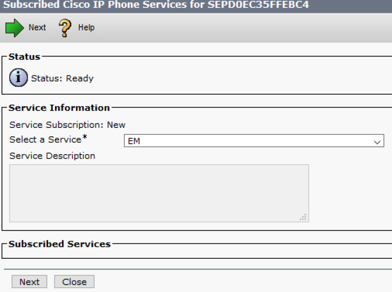
Figure 7-33 Subscribed IP Phone Services
The page in the popup window will refresh to look as shown in Figure 7-34. At this point, you click Subscribe.
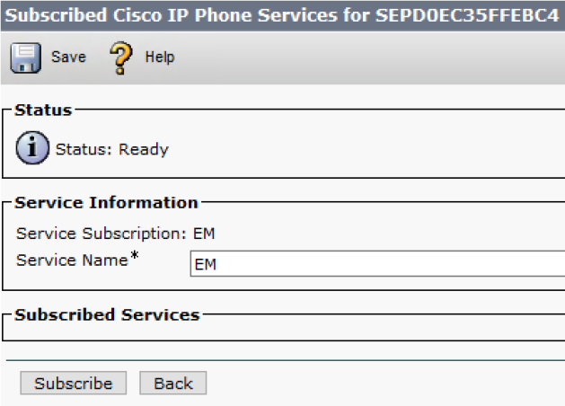
Figure 7-34 Subscribed IP Phone Services Refresh
The page in the popup window refreshes one more time so that it looks as shown in Figure 7-35. Notice the phone service is now listed in the Subscribed Service section. Nothing else needs to be done in this window, and you can close it.

Figure 7-35 The Phone Is Subscribed to EM
Next, you need to configure a device profile and subscribe it to the EM service as well. To add a device profile, navigate to Cisco Unified CM Administration > Device > Device Settings > Device Profile and click Add New. The device profile type, as shown in Figure 7-36, may match the phone model where the user will log in. It is ideal to match the device profile type with the phone model, but this matching is not required (as discussed later in this chapter).
Note
It is important to ensure that the device profile is subscribed to the phone service for EM. If it is not, users who log in to EM will not be able to log out of their profile due to the missing subscription on the device profile.
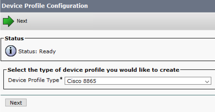
Figure 7-36 Device Profile Type
Click Next, and a new page opens with all the fields ready to be populated for the device profile. Figure 7-37 shows an example with the fields Device Profile Name, Phone Button Template, and Softkey Template modified.

Figure 7-37 Device Profile Configuration
When the device profile is saved, it is possible to add a directory number to it. The number used on this profile is 3333, which makes it easy to tell if the login is successful and the profile is applied to the desk phone. Finally, the device profile needs to be subscribed to the EM phone service using the same steps for the desk phone (refer to Figures 7-32 through 7-35 for these steps).
Now you need to associate the end user with the device profile. To do this, you need to navigate back to the end user (test_em in this case) and scroll down to the Extension Mobility section. To associate the device profile with the end user, move the profile from the Available Profiles box to the Controlled Profiles box, as shown in Figure 7-38.

Figure 7-38 End-User Controlled Profiles
Finally, you need to restart the phone to ensure that the EM service you created is populated on the phone. After you restart the phone, you can test logging in to the phone by following these steps:
Step 1. Press the hard button on the phone that shows a gear icon (see Figure 7-39).
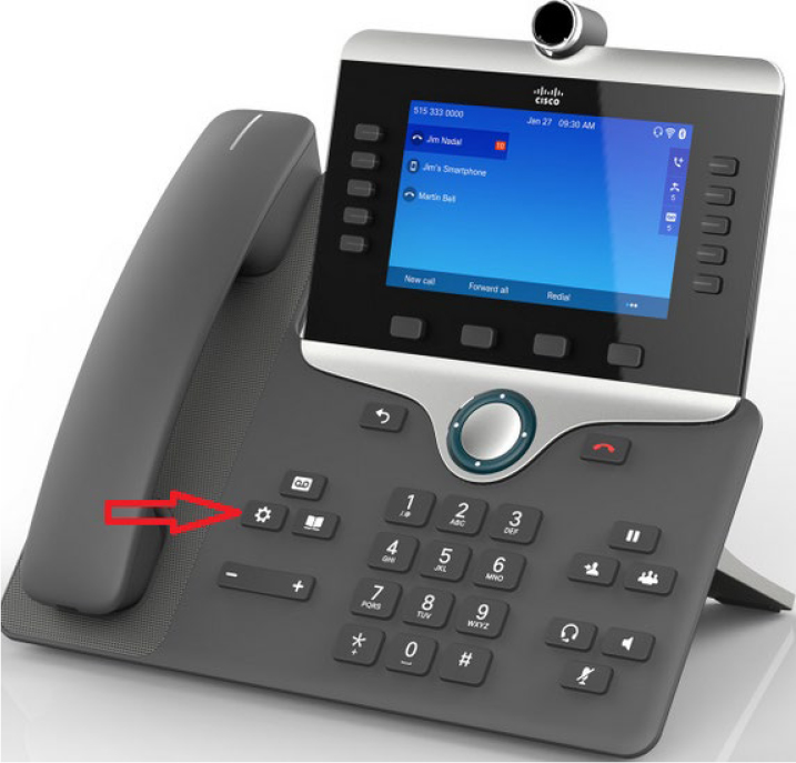
Figure 7-39 Gear Icon Button
Step 2. When the Applications screen opens, select the phone service, as shown in Figure 7-40.
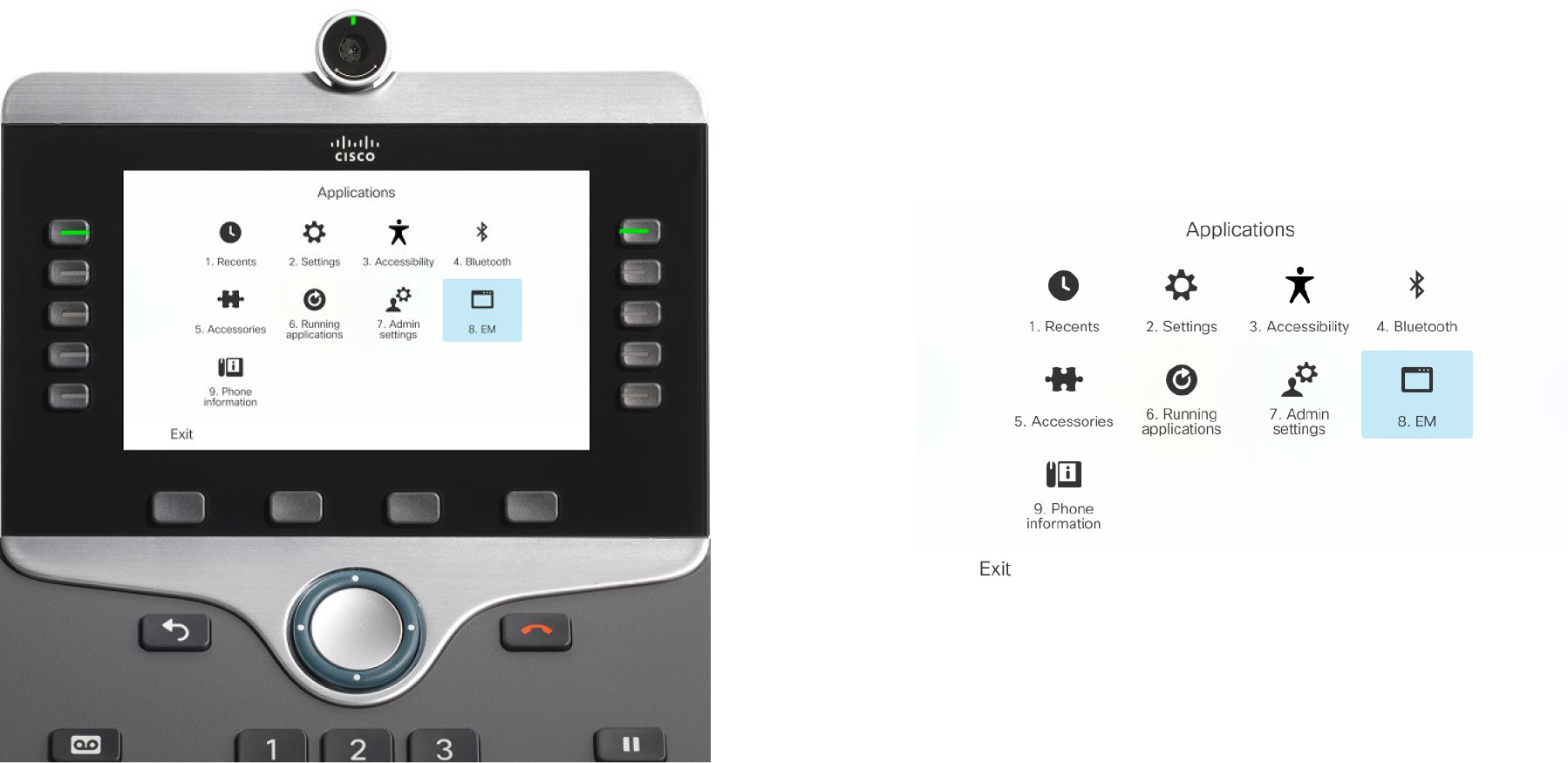
Figure 7-40 Applications Screen Phone UI
Step 3. Enter the credentials for the user, as shown in Figure 7-41, and press the Submit button.
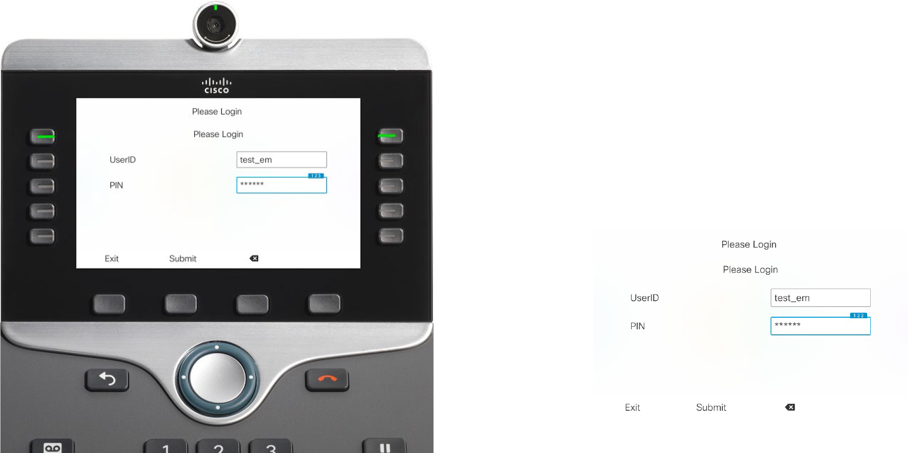
Figure 7-41 User Login Credentials
The phone’s screen displays the login response Login Successful, as shown in Figure 7-42. The screen also informs the user of a phone reset.
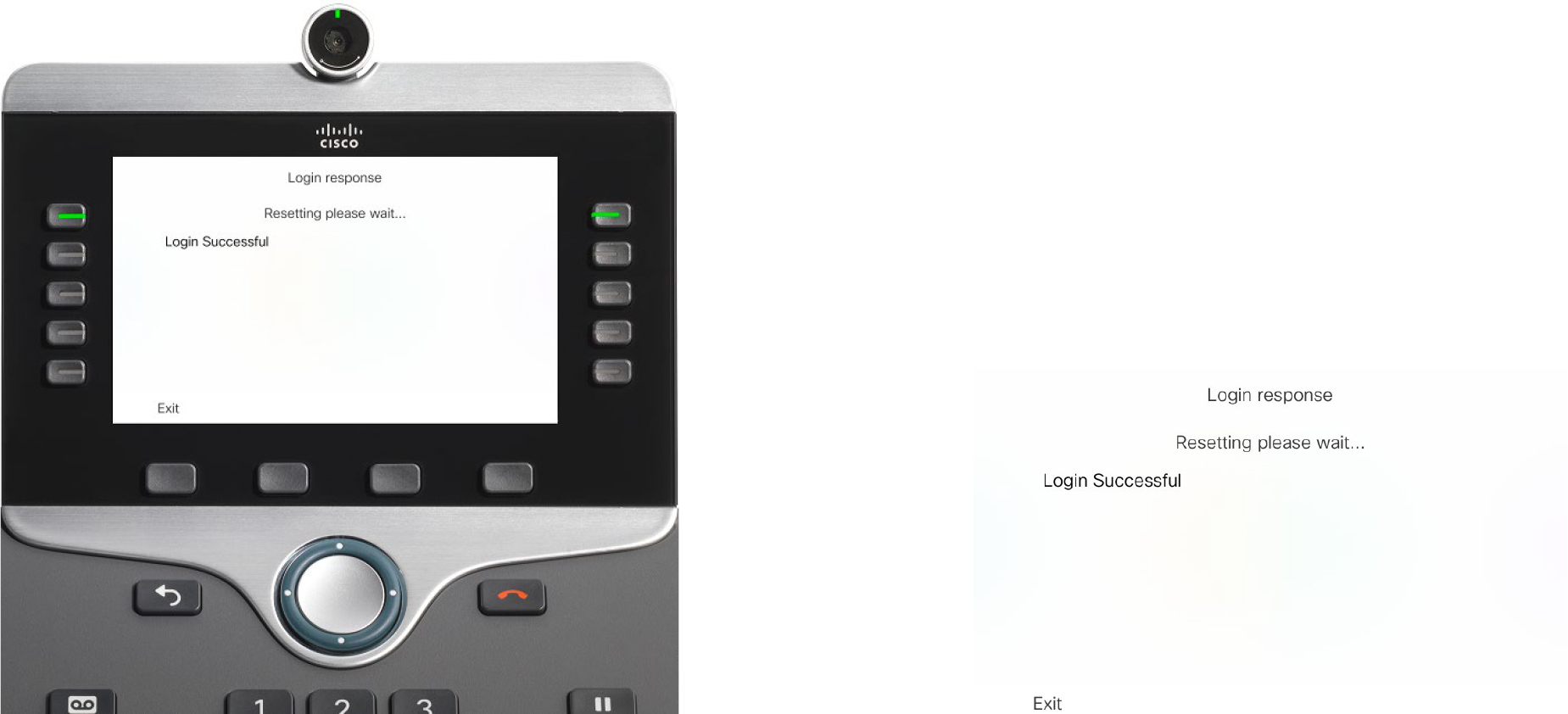
Figure 7-42 Phone Screen Successful Login
After the phone reset, the screen on the phone shows the settings (directory number) of the phone profile, as shown in Figure 7-43.

Figure 7-43 Phone Screen with Device Profile Directory Number
You can determine whether a user is logged in to a phone by accessing the phone’s configuration page in Unified CM and checking the Extension Information section, as shown in Figure 7-44. Also, you can log the user out from this page as well.

Figure 7-44 Extension Information Phone Configuration Page
Figure 7-45 shows the EM logout screen on the phone. To log out of the profile, press the gear icon button, select the phone service from the Applications page, and press the Yes button.
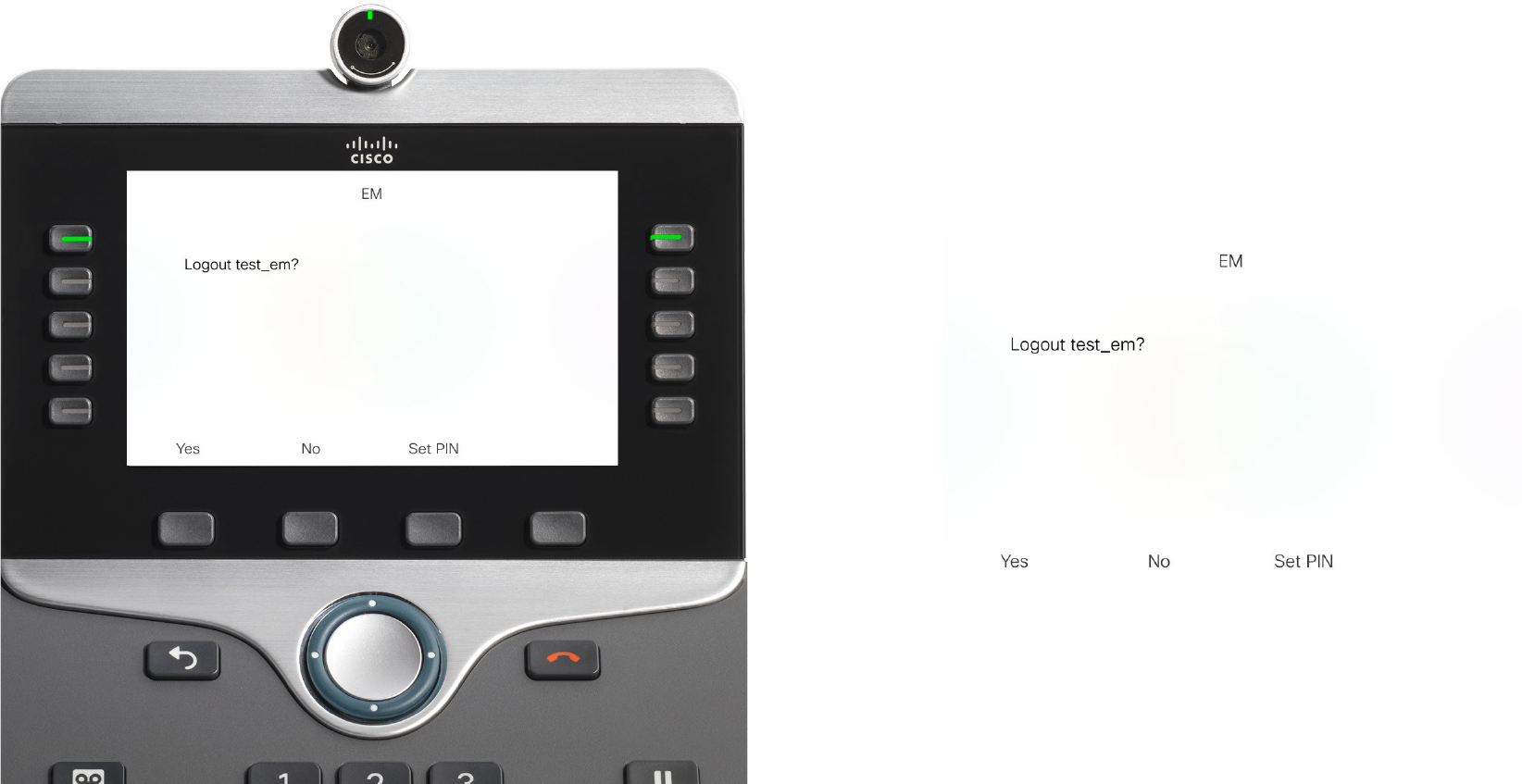
Figure 7-45 Phone Screen Extension Mobility Logout
Tip
You can remotely test Extension Mobility login and logout by using a web browser. To understand the following tests for logging in and logging out, you need to know these prerequisites:
• The server running the EM service is sj-cucm.ccnpcollab.lab.
• The MAC address of the test phone is SEPC4B36ABA1B5A.
• The user ID of the test user is test_em.
• The pin of the test user is 134679.
Using this information, you can use the following URL to log in:
http://sj-cucm.ccnpcollab.lab/emapp/EMAppServlet?device=SEPC4B36ABA1B5A&userid=test_em&seq=134679
You can use this URL to log out:
http://sj-cucm.ccnpcollab.lab/emapp/EMAppServlet?device=SEPC4B36ABA1B5A&doLogout=true
As mentioned earlier in this section, it is not necessary to match the device profile type with the phone model of the desk phone. It is ideal to match them, but it is not necessary. When the profiles don’t match, the default device profile for the desk phone’s model is used. You can find the default device profiles by navigating to Cisco Unified CM Administration > Device > Device Settings > Default Device Profile. The default device profiles are added automatically for each model registered to a cluster. You can create your own default device profiles, per model, if you choose to. The value in creating a default device is that you can make sure the proper phone button templates, softkey templates, and other settings are applied to the phone when a mismatched profile is used to log in.
You can tweak parameters pertaining to Extension Mobility by navigating to Cisco Unified CM Administration > System > Service Parameters > Server > Cisco Extension Mobility and clicking Advanced. The page should look as shown in Figure 7-46.
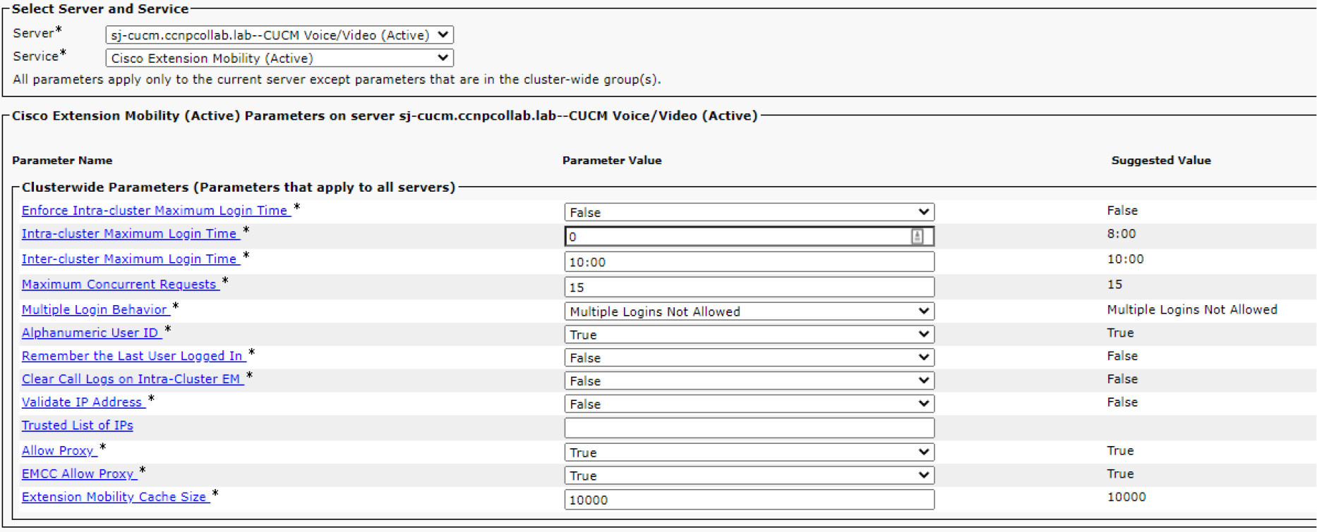
Figure 7-46 Extension Mobility Service Parameters
The following parameters are often modified for Extension Mobility due to their potential impact on the system or security:
• Enforce Intra-cluster Maximum Login Time: The default setting for this parameter is False; however, you can set it to True in order to prevent people from remaining logged in when they’re likely no longer at work. The duration of time is measured in hours; the default value is 0, and the suggested value is 8 hours (specified as 8:00). The time is set in the parameter named Intra-cluster Maximum Login Time.
• Maximum Concurrent Requests: The default value is 15, which matches the suggested value, and this parameter determines how many login and logout operations the system can handle at the same time. You can modify this value in order to adjust the amount of system resources used by the Extension Mobility service.
• Multiple Login Behavior: This parameter specifies what occurs when a user attempts to log in to a phone while their profile is already logged in to another phone. The available values are Multiple Logins Allowed, Multiple Logins Not Allowed, and Auto Logout. When it is set to Multiple Logins Allowed, the user can log in to multiple phones; however, the user can only log in to a single phone when the parameter is set to Multiple Logins Not Allowed. When the parameter value is Auto Logout, the user is permitted to log in to the phone but is logged out of the other phone where their profile is active.
• Validate IP Address: This parameter is set to False by default. When set to True, Unified CM validates the IP address of the source requesting login or logout. It is important to note that when the value is True, login and logout times are slightly longer because it takes time for Unified CM to validate the source.
Troubleshoot Extension Mobility
When people make mistakes setting up Extension Mobility, they will likely make one of these common misconfigurations:
• Not enabling the device for Extension Mobility
• Not enabling the user for Extension Mobility
• Not enabling the service when it is created
• Not subscribing the phone to the service, resulting in the phone not being able to log in to Extension Mobility or see the Extension Mobility service on the phone
• Not subscribing the device profile to the service
Note
When the profile isn’t subscribed to the Extension Mobility service, the user can log in to the phone but cannot log out of the phone. This is because the Extension Mobility service is not present once the user profile is applied. Refer to Figure 7-40 to recall what it looks like when it is present.
• Not associating the profile to the user
• Initial Trust List (ITL) issues preventing the phone from connecting to a secure service URL
To troubleshoot Extension Mobility when the configuration seems correct, it is important to know the login flow. Before we discuss those details, let's discuss the Services Provisioning enterprise parameter. You can modify this parameter, shown in Figure 7-47, by navigating to Cisco Unified CM Administration > System > Enterprise Parameters. The parameter can be set to Internal, External, or Both. The default value for Services Provisioning is Internal. When it is set to External or Both, the phones send an HTTP GET message to Unified CM in order to ask Unified CM which services are available to the phone. When it is set to Internal, phones reference their local configuration file to determine which services are available. Example 7-21 shows how the configuration file stores the Extension Mobility service configured earlier in this chapter. Figure 7-48 outlines the login flow, which involves the steps of the Extension Mobility login flow as described below.
Example 7-21 Phone Configuration File Service
##### The phone's configuration file shows the EM URL as listed below
<phoneService  type="0” category="0">
<displayName>EM</displayName><name>EM</name>
<url>http://sj-cucm.ccnpcollab.lab:8080/emapp/EMAppServlet?device=#DEVICENAME#</url>

Figure 7-47 Services Provisioning Enterprise Parameter
![]()
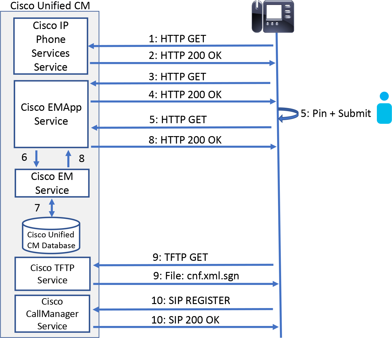
Figure 7-48 EM Login Flow
Note
Steps 1 and 2 do not occur when the Services Provisioning parameter is set to Internal.
Step 1. When the user presses the gear icon button on the phone, the phone performs a call to determine what applications (including phone services) are available to the phone. The call is sent to the server, which is configured in the URL Services enterprise parameter. This is done via an HTTP GET request from the IP phone to the Unified CM.
Step 2. The Cisco IP Phone Services service is queried to determine which services the phone is subscribed to. The list is sent to the phone in a 200 OK HTTP response.
Step 3. When the user selects the Extension Mobility phone service, an HTTP GET request is sent to the Extension Mobility Application (EMApp) service which forwards the request to the Extension Mobility service (see Example 7-22).
Example 7-22 CallManager SDL Trace, EMApp Trace, Extension Mobility Trace, and Cisco TFTP Trace Analysis, Part 1
##### EMApp Trace - The EMApp service receives a request from the phone
2020-01-29 14:57:11,346 INFO  [http-bio-8080-exec-9] EMAppServlet              - EMApp Request# ----->10
2020-01-29 14:57:11,355 INFO  [http-bio-8080-exec-9] EMAppServlet              - EMAppServlet: Request protocol is :http
2020-01-29 14:57:11,360 INFO  [http-bio-8080-exec-9] EMAppServlet              - EMApp Request parameters: Logout=null Device Name=SEPD0EC35FFEBC4 User Id=null Device Profile=null Refresh=null Remote Host IP Address = 14.50.214.106 Via Header Set = false getClusterInfo = null Lang = en_US Charset=utf-8,;q=0.8 Emcc = null LoginType = null
##### EMApp Trace - The EMApp service forwards the query to the EM Service
2020-01-29 14:57:11,407 DEBUG [http-bio-8080-exec-9] EMServiceCommunicator     - Posting to EM Service:<query>
  <appInfo>
      <appID>CCMSysUser</appID>
      <appEncryptedCertificate>xxxxxxx</appEncryptedCertificate>
  </appInfo>
  <deviceUserQuery>
      <deviceName>SEPD0EC35FFEBC4</deviceName>
     <remoteIPAddr>14.50.214.106</remoteIPAddr>
  </deviceUserQuery>
</query>
2020-01-29 14:57:11,407 INFO  [http-bio-8080-exec-9] EMServiceCommunicator     - Posting to EM Query Service:https://localhost:8443/emservice/EMServiceServlet
##### EM Trace - The EM service receives the request from EMApp
2020-01-29 14:57:11,536 INFO [http-bio-8443-exec-1] EMServiceServlet - EMService Request# ----> : 6
##### EM Trace - We see the request is to determine the device to user association “deviceUserQuery"
2020-01-29 14:57:11,540 DEBUG [http-bio-8443-exec-1] EMServiceServlet          - 6:Query-><?xml version="1.0"?>
<!DOCTYPE query SYSTEM “http://172.18.110.61:8080/emservice/jsp/LoginQuery.dtd">
<query>
  <appInfo>
      <appID>CCMSysUser</appID>
      <appEncryptedCertificate>*****</appEncryptedCertificate>
  </appInfo>
  <deviceUserQuery>
      <deviceName>SEPD0EC35FFEBC4</deviceName>
     <remoteIPAddr>14.50.214.106</remoteIPAddr>
  </deviceUserQuery>
</query>
Step 4. In response to the call made in step 3, the EMApp service forwards an XML message to the phone, requesting the user’s credentials for EM login. The XML is carried within the 200 OK HTTP response. Example 7-23 shows a snippet from the trace log indicating that the login page has been sent. The 200 OK message from EMApp to the phone instructs the phone to display the login screen and request the user ID and PIN.
Example 7-23 CallManager SDL Trace, EMApp Trace, Extension Mobility Trace, and Cisco TFTP Trace Analysis, Part 3
##### EMApp Trace - The login page is sent to the phone
2020-01-29 14:57:11,712 INFO [http-bio-8080-exec-9] EMAppServlet - Sent login page for device SEPD0EC35FFEBC4
Step 5. The user enters their credentials in the phone’s UI and then presses the Submit button to send the data to the EMApp service. An HTTP GET, containing the user’s credentials, is sent to Unified CM for verification. Example 7-24 shows the trace snippets for this operation.
Example 7-24 CallManager SDL Trace, EMApp Trace, Extension Mobility Trace, and Cisco TFTP Trace Analysis, Part 4
##### EMApp Trace - EMApp gets another request from the phone. This time the phone is sending the user credentials
2020-01-29 14:57:33,236 INFO  [http-bio-8080-exec-11] EMAppServlet              - EMApp Request# ----->11
2020-01-29 14:57:33,236 INFO  [http-bio-8080-exec-11] EMAppServlet              - EMAppServlet: Request protocol is :http
2020-01-29 14:57:33,237 INFO  [http-bio-8080-exec-11] EMAppServlet              - EMApp Request parameters: Logout=null Device Name=SEPD0EC35FFEBC4 User Id=test_em Device Profile=null Refresh=null Remote Host IP Address = 14.50.214.106 Via Header Set = false getClusterInfo = null Lang = en_US Charset=utf-8,;q=0.8 Emcc = null LoginType = null
Step 6. As shown in Example 7-25, the EMApp service proxies the information to the Extension Mobility service.
Example 7-25 CallManager SDL Trace, EMApp Trace, Extension Mobility Trace, and Cisco TFTP Trace Analysis, Part 5
##### EMApp Trace - The EMApp service sends the information to the EM Service
##### EMApp Trace - This is going to the login service specifically
2020-01-29 14:57:33,342 DEBUG [http-bio-8080-exec-11] EMServiceCommunicator     - Posting to EM Service:<request>
  <appInfo>
      <appID>CCMSysUser</appID>
      <appEncryptedCertificate>xxxxxxx</appEncryptedCertificate>
  </appInfo>
  <login>
      <deviceName>SEPD0EC35FFEBC4</deviceName>
      <userID>test_em</userID>
      <deviceProfile>test_em_dev_pro</deviceProfile>
      <remoteIPAddr>14.50.214.106</remoteIPAddr>
      <isViaHeaderSet>false</isViaHeaderSet>
  </login>
</request>
Step 7. The Extension Mobility service queries the Cisco Unified CM database to determine the device profile to use and apply the settings of the device profile to the phone’s configuration. Example 7-26 shows the login was successful.
Example 7-26 CallManager SDL Trace, EM App Trace, EM Trace, and Cisco TFTP Trace Analysis, Part 6
##### EM Trace – The login to the device is successful
2020-01-29 14:57:33,877 INFO  [http-bio-8443-exec-18] EMServiceServlet          - 7:Request succeeded returning<?xml version=”1.0”?>
<response>
<success/>
</response>
Step 8. The Extension Mobility service informs the EMApp service of the successful login and the EMApp service then responds to the phone with an HTTP 200 OK.
Step 9. The CallManager service sends a restart message to the phone. As part of the restart process, the phone requests the appropriate Extension Mobility configuration. Example 7-27 shows the TFTP service receiving the request and building the updated configuration file, which includes the settings from the device profile.
Example 7-27 CallManager SDL Trace, EMApp Trace, Extension Mobility Trace, and Cisco TFTP Trace Analysis, Part 7
##### At this point the phone is coming back online and needs to contact TFTP for its configuration file
##### TFTP Trace - TFTP Trace - The device requests the config file from TFTP after login
00022631.003 |14:57:40.200 |AppInfo  |   HTTPConnection::wait_SdlDataInd Printing the HTTPRequest : msgBuffer size [70] --: GET /SEPD0EC35FFEBC4.cnf.xml.sgn HTTP/1.1
Host:172.18.110.61:6970
##### TFTP Trace - TFTP builds the config file with the understanding the EM user is logged with profile test_em_dev_pro
00022634.059 |14:57:40.283 |AppInfo |CXMLSIPLines::BuildFromRecord(), Device[SEPD0EC35FFEBC4] Id[9d728269-56fe-43ae-bd99-02b77a14d572], EM Loged in using DeviceProfile[test_em_dev_pro], Id[4dc5e067-e181-6b9f-4ce6-a7c988a9c28f]
Step 10. Finally, as shown in Example 7-28, with the phone configuration downloaded, the IP phone re-registers with Unified CM by sending a SIP REGISTER message. Unified CM would accept the registration with a SIP 200 OK response.
Example 7-28 CallManager SDL Trace, EM App Trace, EM Trace, and Cisco TFTP Trace Analysis, Part 8
##### Now the phone knows which Unified CM to use and which DN to use
##### CallManager SDL Trace - CCM receives REGISTER message from the phone, now using extension 3333
00558862.004 |14:57:44.589 |AppInfo  |SIPTcp - wait_SdlReadRsp: Incoming SIP TCP message from 14.50.214.106 on port 49907 index 2895 with 2589 bytes:
[54911,NET]
REGISTER sip:sj-cucm.ccnpcollab.lab SIP/2.0
From: <sip:3333@sj-cucm.ccnpcollab.lab>;tag=d0ec35ffebc4002313443e01-78d68621
To: <sip:[email protected]>
Call-ID: [email protected]
CSeq: 121 REGISTER
Reason: SIP;cause=200;text="cisco-alarm:23 Name=SEPD0EC35FFEBC4 ActiveLoad=sip8845_65.12-7-1-0001-393.loads InactiveLoad=sip8845_65.12-1-1SR1-4.loads Last=reset-restart"
One of the great things about Extension Mobility is the error codes provided when something goes wrong. Any time there is an issue with Extension Mobility login or logout, the first thing you want to know is the error code on the screen. For example, say that the user is trying to log in to the phone and sees the message “Login is unavailable(28)”. Based on the sample output and the information in Table 7-2, you can surmise the meaning of this error code and how to fix it. This error was an Extension Mobility service error code, which is different than EM Application errors.
Table 7-2 EM Service Error Codes
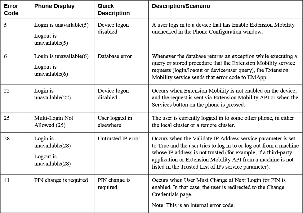
Table 7-2 details only a few of the common errors you might encounter. The full list of Extension Mobility error codes, along with detailed reasons, is too long to print in this book, but you can find a digital version in the Unified CM feature configuration guide, at https://www.cisco.com/c/en/us/td/docs/voice_ip_comm/cucm/admin/12_5_1/featureConfig/cucm_b_feature-configuration-guide-1251/cucm_b_feature-configuration-guide-1251_chapter_011110.html.
Note
Some of the error messages in this table are for Extension Mobility Cross Cluster; however, this book focuses on only Extension Mobility.
Table 7-3 details some other error codes, which are more likely to occur when EMApp has a problem. As you will see later in this chapter, knowing whether the Extension Mobility service or EMApp is facing issues can greatly reduce your troubleshooting efforts.
Table 7-3 Phone Display Messages from EMApp

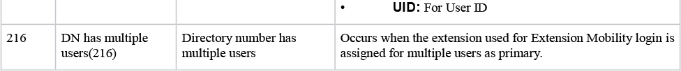
Configure and Verify Device Mobility
Users sometimes move between buildings, sites, regions, and countries. In the process, a user might bring their phone with them; however, the user is more likely to take only their computer and mobile device. This is not an issue on the surface; however, there are concerns about settings applied to the device and/or device pool. The following are some of those settings:
• SRST Reference
• Date/Time Group
• Region
• Location
• Calling Search Space
• Media Resources
Consider an example of why these settings might be problematic: Say that a user moves from a site in Mexico to a site in the United States. While in the United States, the user initiates an ad hoc conference, and the conference bridge selected is in Mexico, even though the user is currently in the United States. A media resource in Mexico is selected due to statically assigned settings, such as the media resource group list. This opens the door for bandwidth issues and possible connectivity issues as well.
The Device Mobility feature addresses these concerns. With this feature, certain settings can be dynamically assigned when a user is roaming.
This section explains the configurations needed for Device Mobility, describes the difference between Roaming Sensitive settings and Device Mobility–Related Information settings, provides a diagram for Device Mobility, and shows how to verify whether a phone is roaming.
Figure 7-49 provides a high-level view of the topology used for the example in this section. This figure will be very important when we talk about Device Mobility–Related Information and its impact on dialing external phone numbers.

Figure 7-49 Domestic Device Mobility Topology
Note
Device Mobility is not a cross-cluster feature. Furthermore, devices with statically assigned IP addresses do not invoke the Device Mobility feature.
Device Mobility might seem complicated at first, but the basic idea is to determine whether an endpoint has changed subnets and whether the endpoint’s settings should be dynamically updated if the device has moved to a new subnet. There are only a few pieces to the configuration, and most of them are simply used to make indirect connections to other pieces of the configuration. The ability to make indirect connections between the Device Mobility settings allows administrators more flexibility in their design. Configuring Device Mobility involves the following steps.
Step 1. Set the Device Mobility mode, which indicates whether Device Mobility is enabled on an endpoint.
Step 2. Configure physical locations, which are used to logically segment low-level areas (buildings, campuses, cities, and so on). A good approach would be to make a physical location per device pool as device pools are typically configured for low-level areas as well.
Step 3. Configure Device Mobility groups, which are used to logically segment high-level areas. Typically, Device Mobility groups are made per country.
Step 4. Configure device pools, which are used to link physical locations and Device Mobility groups to the Roaming Sensitive settings and Device Mobility–Related Information. In more direct terms, the device pool helps identify settings that should be dynamically assigned to a roaming device. A static device pool is configured on a phone’s configuration page. A roaming device pool is a device pool that is dynamically applied to the phone while the phone is roaming to a new subnet.
Step 5. Configure Device Mobility information to specify which subnet is associated with which device pool(s).
Figure 7-50 provides an illustration that shows how these elements connect in a real-world example.
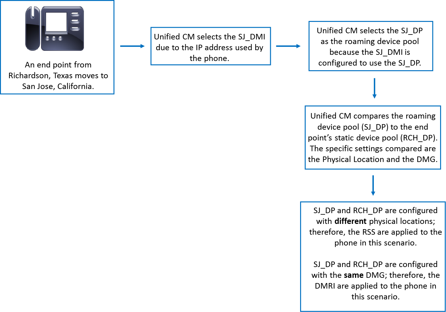
Figure 7-50 Device Mobility Example
Note
Notice that the Roaming Sensitive settings are applied when the physical location is different between device pools, but the Device Mobility–Related Information is applied when the Device Mobility group is the same between device pools.
Let’s talk about each of the configurations, starting with how to set the Device Mobility mode. There are two ways to set Device Mobility mode: via a service parameter or via the device configuration page. When Device Mobility mode is set at a service parameter level, all devices that reference the service parameter configuration are either set to on or off, depending on what value is chosen for the service parameter. The value originally specified on the phone configuration page for Device Mobility mode is Default. This means the phones, by default, reference the service parameter; furthermore, the default setting for the Device Mobility mode service parameter is off. Figure 7-51 shows the Device Mobility mode setting on the phone configuration page, and Figure 7-52 shows the service parameter. For simplicity, the configuration in this chapter uses the service parameter by setting the Device Mobility Mode parameter to On. To review or modify the service parameter, navigate to Cisco Unified CM Administration > System > Service Parameters > Server > Cisco CallManager and then locate the parameter in the section Clusterwide Parameters (Device - Phone).
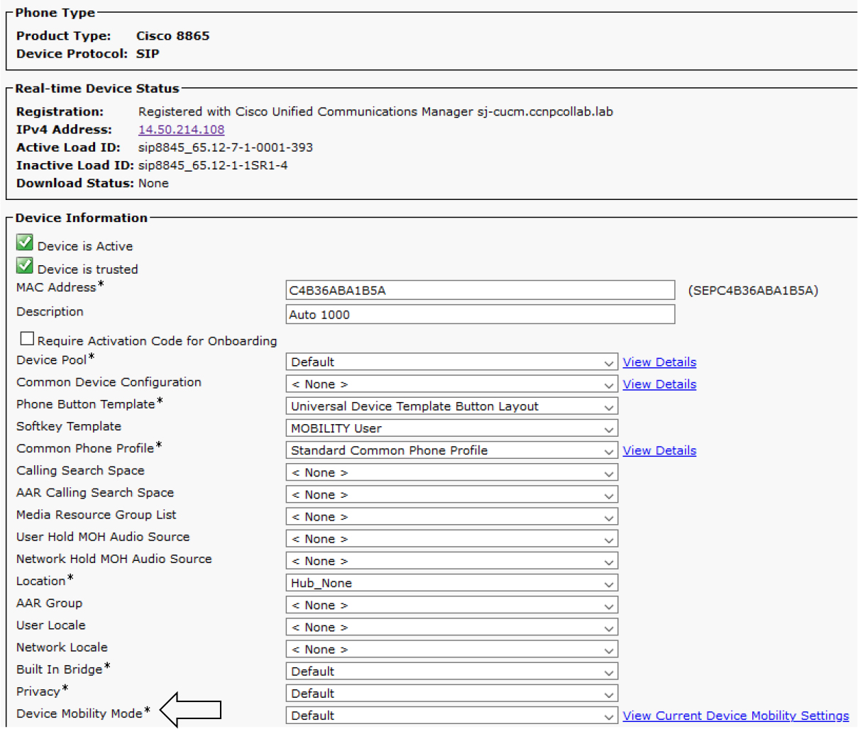
Figure 7-51 Device Mobility Mode Setting on a Phone

Figure 7-52 Device Mobility Mode Setting Service Parameter
To create physical locations, you navigate to Cisco Unified CM Administration > System > Physical Location and click Add New. The configuration here is simple as you only need to provide a name and an optional description. Figure 7-53 shows what the Physical Location Configuration page looks like, and Figure 7-54 shows three physical locations added to the configuration for testing.

Figure 7-53 Physical Location Configuration Page
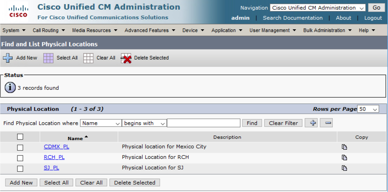
Figure 7-54 Three Physical Locations Added
Note
Physical locations are typically configured based on Class of Control (CAC) and media resources.
Next, you need to add a Device Mobility group to the configuration. To do this, you navigate to Cisco Unified CM Administration > System > Device Mobility > Device Mobility Group and click Add New. As with the physical location configuration, Device Mobility groups simply require a name and an optional description. Figure 7-55 shows that the test configuration uses three Device Mobility groups.
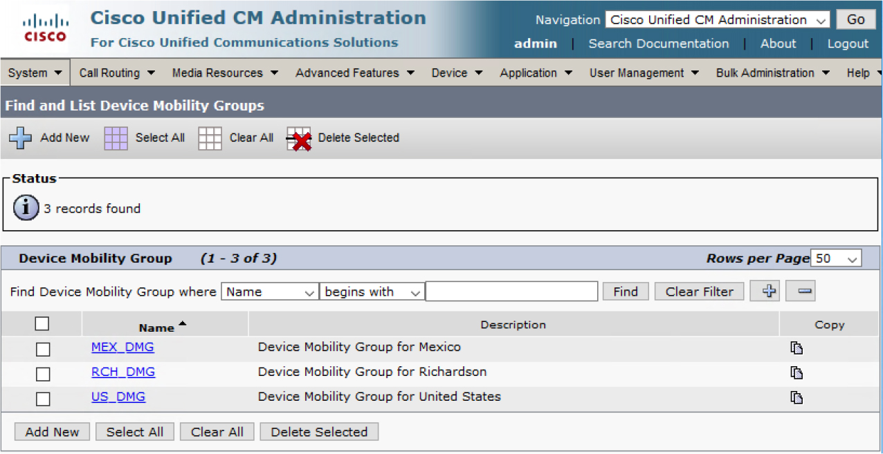
Figure 7-55 Three Device Mobility Groups
Note
Device Mobility groups are typically configured with consideration of maintaining user dialing habits. For example, someone from Europe who traveled to America might not be familiar with how to dial external numbers. Device Mobility Groups allow them to maintain their typical dialing instead of learning how to dial external numbers while in America.
Next, you need to configure device pools (unless they are already configured, as they are when implementing Device Mobility in a preexisting environment). To configure device pools, navigate to Cisco Unified CM Administration > System > Device Pool and click Add New to create a device pool or click Find to edit an existing device pool.
Table 7-4 shows the two settings that can be configured for a device pool.
Table 7-4 Device Pool Roaming Sensitive Versus Device Mobility Related Information
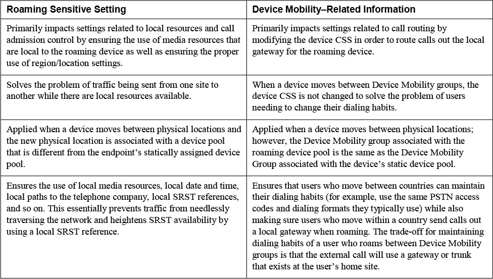
Note
This section of the chapter is written with a traditional dial plan in mind; however, some notes about the impacts of globalized dial plans are provided where appropriate. Globalized dial plans greatly simplify configurations for advanced features and advanced call routing setups. When using globalized dial plans with Device Mobility, end-user dialing habits are maintained due to number globalization and localization; furthermore, the local gateway is always used due to the local route group feature, which is defined on the roaming device pool. In short, globalized dial plans eliminate the need for Device Mobility Groups.
Figure 7-56 shows the Roaming Sensitive Settings section of the Device Mobility configuration.
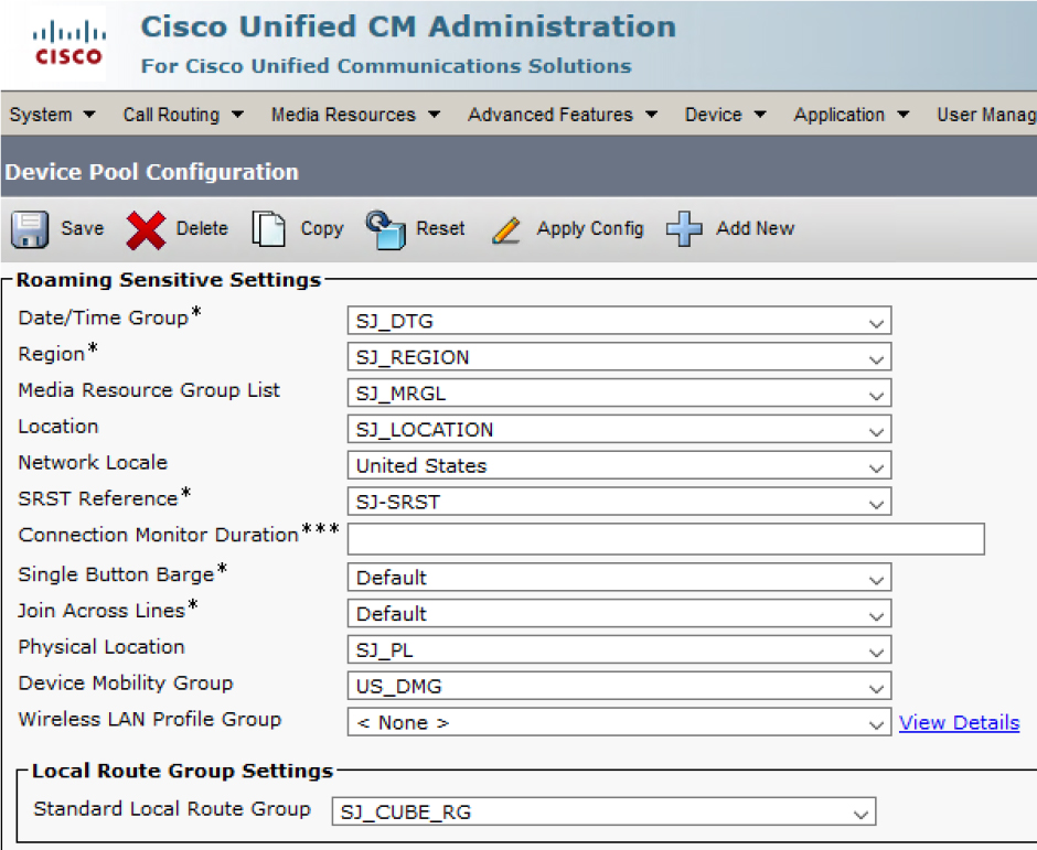
Figure 7-56 Roaming Sensitive Settings Section
Notice that these settings are primarily related to a device moving from one campus to another or one city to another, and they don’t impact a user’s dialing habits. For example, if someone from the SJ site takes a device to the RCH office, the device will then be in a different time zone and warrant use of a different date/time group.
Figure 7-57 shows the Device Mobility Related Information configuration settings, and you can see these settings pertain only to call routing. You can use these settings to preserve a user’s ability to dial as they normally would. For example, when a user from CDMX visits SJ, they will change Device Mobility groups. You might want to allow the user to dial the same way they would while in Mexico. Then, when she changes Device Mobility groups, the Device Mobility–Related Information settings are ignored. This means the static CSS remains applied from user’s device, and the user can maintain their typical dialing habits.
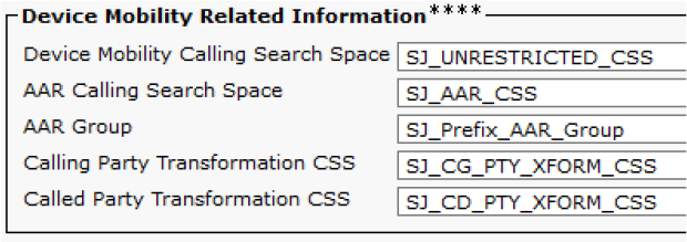
Figure 7-57 Device Mobility Related Information Section
Tip
There are overlapping settings between a phone and a device pool. The settings on the phone take precedence over those on the local device pool, but the roaming device pool has the highest precedence when the device is roaming.
The final item to configure is Device Mobility information. To do this, you navigate to Cisco Unified CM Administration > System > Device Mobility > Device Mobility Info and click Add New. Figure 7-58 shows what the Device Mobility Info Configuration page looks like. This example shows the creation of Device Mobility Information for CDMX and SJ. The CDMX Device Mobility Information links the subnet 14.48.38.0 /24 to the CDMX_DP device pool while the SJ Device Mobility Information links the 14.50.214.0 /24 subnet to the SJ_DP device pool.

Figure 7-58 Device Mobility Info Configuration Page
Figure 7-59 shows that Device Mobility information may be associated with one device pool or with multiple device pools. Also, a device pool can be associated with one or more Device Mobility Information configurations. In reviewing the figure, we can see the one-to-one association between Device Mobility Information A and Device Pool A, the single Device Mobility Information to multiple device pool association between Device Mobility Information B and Device Pools A and C, and the single device pool to multiple Device Mobility Information association between Device Pool C and Device Mobility Information B and C.
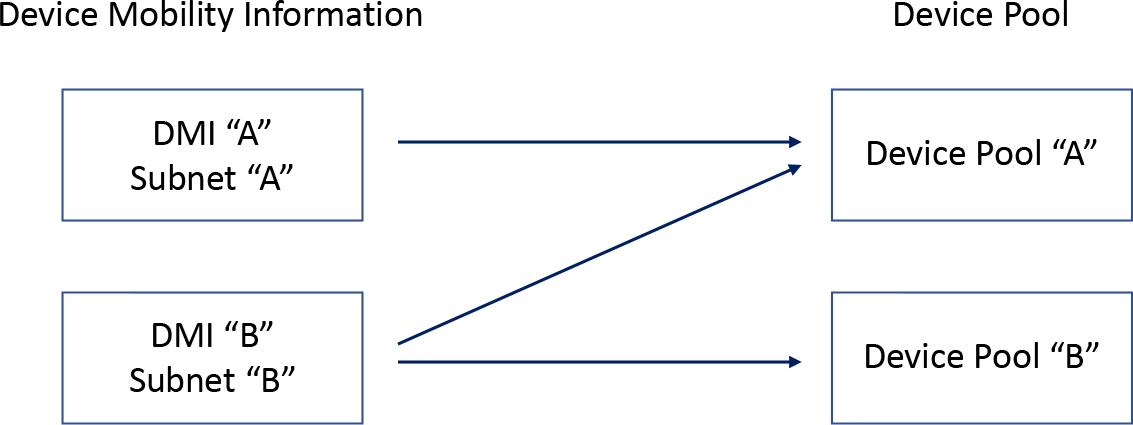
Figure 7-59 DMI-to-Device Pool Relationships
Now let’s look at how all these settings come together. Figure 7-60 shows the logic diagram used to determine whether a device is roaming and whether the device’s settings should be dynamically modified.
![]()
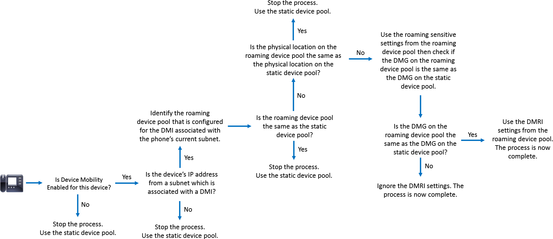
Figure 7-60 Device Mobility Logic Diagram
To test the Device Mobility configuration, you can take a phone from the CDMX site and bring it to the SJ site. The expected behavior is as follows:
Step 1. The phone gets a new IP address for the SJ subnet from DHCP located in SJ.
Step 2. The SJ subnet is associated with a the Device Mobility Information named SJ_NETWORK_DMI; therefore, Unified CM identifies the device pool associated with this Device Mobility Information.
Step 3. The roaming device pool is the SJ_DP device pool. This is different from the phone’s static device pool, which is CDMX_DP; therefore, the Roaming Sensitive settings of SJ_DP are applied to the phone.
Step 4. Unified CM checks whether the roaming Device Mobility group (US_DMG) is different from the phone’s static Device Mobility group (MEX_DMG). Because it is different, the Device Mobility–Related Information is ignored.
Now you need to confirm that the phone is roaming and determine which roaming settings are applied to the phone. One way to know if a phone is roaming is to reset the phone and see if the screen of the phone displays the message shown in Figure 7-61. This message appears after the phone registers, but it does not remain on the screen for long.

Figure 7-61 Phone Screen for a Roaming Device
Another way to tell if a device is roaming is to check the current Device Mobility settings on the phone’s configuration page in Unified CM. Figure 7-62 shows where to find this option.

Figure 7-62 View Current Device Mobility Settings
When you click on View Current Device Mobility Settings, you see the information shown in Figure 7-63. Note that this figure shows the settings while the phone is roaming. Figure 7-64 shows the static device pool settings applied to the device when it is not roaming. When a device is not roaming, the Roaming Sensitive Settings reflect the static settings and they appear grey as seen in Figure 7-64.

Figure 7-63 Current Device Mobility Settings for a Roaming Device
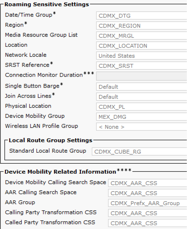
Figure 7-64 Static Device Pool Settings for a Device That Is Not Roaming
The easiest way to compare the current Device Mobility settings to the static device pool settings is to click on View Details next to the Device Pool field on the phone’s configuration page (see Figure 7-65).

Figure 7-65 Device Pool View Details Button
Troubleshoot Device Mobility
To troubleshoot Device Mobility, it is important to know the logic of Device Mobility (refer to Figure 7-60).
When troubleshooting issues that might be affected by Device Mobility, such as call routing issues, it can be helpful to disable the Device Mobility mode on some test phones. Then you can try to reproduce the issue at hand to determine if Device Mobility is a factor to consider while troubleshooting.
You should also be familiar with how CallManager SDL trace logs look for a working scenario. Example 7-30 provides an example, where the following process occurs:
Step 1. Unified CM prints a clear line about the device registering and indicates that a device is roaming.
Step 2. Unified CM adds the device to the Device Mobility route table and documents the static and roaming device pools.
Step 3. Unified CM sends a SIP REFER message to the phone so the phone can display “Device in Roaming Location".
Step 4. The phone replies to the REFER message with a 200 OK message.
Example 7-30 CallManager SDL Trace
##### Step 1
01998705.049 |22:45:30.974 |AppInfo  |SIPStationD(28) - setIPAddr: Registering phone IP: 14.50.214.111

01998726.002 |22:45:30.987 |AppInfo  |mMobileDevice = 1
##### Step 2
01998726.003 |22:45:30.987 |AppInfo |DeviceManager::addMobileDevice - added mobile device to Device Mobility Route Table. DeviceName=SEPD0EC35FFB4C4, DeviceType=36225 IpAddr=6AD6320E, DevicePool=CDMX_DP(3529fd90-bf5e-8765-87b0-2ecf0d281cc7), RoamingDevicePool=SJ_DP(3f6bb86d-4d49-a843-24d6-bc928ecaf337), EMCCGeoLocationFilter=, DeviceGeoLocation=[], GeoLocationTokensMatched=0
##### Step 3
01998737.001 |22:45:30.999 |AppInfo  |//SIP/SIPUdp/wait_SdlSPISignal: Outgoing SIP UDP message to 14.50.214.111:[5060]:
[196878,NET]
REFER sip:[email protected]:5060;transport=udp SIP/2.0
From: <sip:[email protected]>;tag=2090933714
To: <sip:[email protected]>
Call-ID: [email protected]
CSeq: 101 REFER
Content-Type: application/x-cisco-remotecc-request+xml
Referred-By: <sip:[email protected]>

<?xml version="1.0” encoding="iso-8859-1"?>
<x-cisco-remotecc-request>
<statuslineupdatereq>
<action>notify_display</action>
<statustext>Device In Roaming Location</statustext>
<displaytimeout>10</displaytimeout>
<priority>1</priority>
</statuslineupdatereq>
</x-cisco-remotecc-request>
##### Step 4
01998750.001 |22:45:31.013 |AppInfo  |//SIP/SIPUdp/wait_SdlDataInd: Incoming SIP UDP message size 574 from 14.50.214.111:[5060]:
[196879,NET]
SIP/2.0 200 OK
From: <sip:[email protected]>;tag=2090933714
To: <sip:[email protected]>;tag=D0EC35FFB4C40010685a1a39-5bc62693
Call-ID: [email protected]
CSeq: 101 REFER
When you check the phone console logs, you see a SIP REFER message from Unified CM that says “Device in Roaming Location” as well as the line shown in Example 7-31, which indicates the phone is localizing the string and provides and ENUM value 24.
Example 7-31 Phone Console Logs from the Problem Reporting Tool (PRT)
5268 DEB Feb 03 21:45:29.253878 (3982-4172) JAVA-SIPCC-SIP_CC_PROV: ccsnap_EscapeStrToLocaleStr: Localized string: [Device In Roaming Location]. (status_index=[0]. stringId enum=[24])
Note
The test phone’s Phone Log Profile parameters were set to Default, Preset, Telephony, SIP, and UI.
References
Cisco, “Feature Configuration Guide for Cisco Unified Communications Manager, Release 12.5(1)SU1,” https://www.cisco.com/c/en/us/td/docs/voice_ip_comm/cucm/admin/12_5_1SU1/cucm_b_feature-configuration-guide-for-cisco1251SU1/cucm_b_feature-configuration-guide-for-cisco1251SU1_chapter_010.html
Cisco, “Cisco Collaboration System 12.x Solution Reference Network Designs (SRND),” https://www.cisco.com/c/en/us/td/docs/voice_ip_comm/cucm/srnd/collab12/collab12/mobilapp.html
Exam Preparation Tasks
As mentioned in the section “How to Use This Book” in the Introduction, you have a couple of choices for exam preparation: the exercises here, Chapter 11, “Final Preparation,” and the exam simulation questions in the Pearson Test Prep software online.
Review All Key Topics
Review the most important topics in the chapter, noted with the key topics icon in the outer margin of the page. Table 7-5 lists these key topics and the page number on which each is found.
![]()
Table 7-5 Key Topics for Chapter 7

Complete Tables and Lists from Memory
There are no memory tables or lists for the chapter.
Define Key Terms
Define the following key terms from this chapter and check your answers in the glossary:
Single Number Reach (SNR)