Chapter 5. Unified CM SIP Trunk Configuration
This chapter covers the following topics:
• SIP Trunk Overview and Configuration: This section details how to configure SIP trunks and the various settings used for interoperability between many different SIP trunk integrations.
• SIP Trunk Features: This section covers a few of the features provided by SIP trunks and their operation.
• Verify and Troubleshoot Unified CM SIP Trunks: This section describes some troubleshooting techniques, tools, and methods that can be used when verifying calls that traverse Unified CM SIP trunks.
This chapter covers the following CLACCM 300-815 exam topics:
• 1.1 Troubleshoot these elements of a SIP conversation
• 1.1.a Early media
• 1.1.d Session timers
• 1.3 Troubleshoot media establishment
• 4.1 Configure these globalized call routing elements in Cisco Unified Communications Manager
• 4.1.g SIP trunking
• 4.2 Troubleshoot these globalized call routing elements in Cisco Unified Communications Manager
• 4.2.g SIP trunking
Cisco Unified Communication Manager (Unified CM) serves many purposes in a unified collaboration network. Primarily, Unified CM enables you to register and manage various collaboration endpoints, such as physical IP phones like the Cisco IP Phone 8865, soft clients like Cisco Jabber, and telepresence desktop endpoints like the Cisco Webex Desk Pro. In addition, Unified CM routes calls and assists in negotiating media capabilities between endpoints. A simple call between two IP phones registered to Unified CM requires minimal configuration, but there are times when Unified CM endpoints need to communicate with devices which use third-party servers, public networks, or even another Unified CM cluster to control their calls. Examples include outbound calls from an IP phone to a mobile phone located on a public network and inbound calls from an IP phone on another Unified CM cluster. To facilitate these types of communication, a Unified CM cluster may be configured to communicate with neighboring devices by using Session Initiation Protocol (SIP) to establish media sessions. This type of peer-to-peer connection between call control devices using SIP is referred to as a SIP trunk.
This chapter focuses on Unified CM SIP trunks and dives into the various sections of the Trunk Configuration page in Unified CM. There are many settings on a Unified CM SIP trunk, and this chapter looks specifically at settings that affect call routing decisions and the SIP signaling used for call routing purposes. In addition to SIP trunks, the chapter discusses other configuration parameters that are required to properly understand the topic, including the SIP trunk security profile and SIP profile. Where possible, real-world examples and scenarios are detailed, along with relevant configuration examples and SDL trace samples.
“Do I Know This Already?” Quiz
The “Do I Know This Already?” quiz allows you to assess whether you should read the entire chapter. If you miss no more than one of these self-assessment questions, you might want to move ahead to the “Exam Preparation Tasks” section of the chapter. Table 5-1 lists the major headings in this chapter and the “Do I Know This Already?” quiz questions related to the material in each of those sections to help you assess your knowledge of these specific areas. The answers to the “Do I Know This Already?” quiz appear in Appendix A, “Answers to the ‘Do I Know This Already?’ Quiz Questions.”
Table 5-1 “Do I Know This Already?” Foundation Topics Section-to-Question Mapping
1. What applications can be integrated with Unified CM using SIP trunks? (Choose three.)
a. Cisco Emergency Responder (CER)
b. Cisco Unity Connection (CUC)
c. Active Directory (AD)
d. Unified instant messaging and presence (IM&P)
e. Cisco Unified Bore Element (CUBE)
2. When Unified CM receives an inbound call over a SIP trunk with calling number 2000 and called number 1000, what device is the calling device, from the perspective of Unified CM?
a. 2000
b. The device with directory number 1000
c. The device with directory number 2000
d. The SIP trunk that is used to receive the inbound call
3. How do you specify the listening port for a SIP trunk in Unified CM?
a. The listening port cannot be changed.
b. Specify the port in the remote destination section of the trunk configuration page.
c. Modify the incoming port on the SIP trunk security profile applied to the trunk.
d. Modify the incoming transport type on the SIP trunk security profile used by the trunk.
4. How can Unified CM determine if the remote peer defined on a SIP trunk is available to receive calls?
a. Check the Dialed Number Analyzer (DNA) tool in Unified CM.
b. SIP is a peer-to-peer protocol, so this is not possible.
c. Use SIP OPTIONS ping.
d. Do a TCP handshake to see if it succeeds.
5. When Media Termination Point Required is enabled on a SIP trunk, what happens when Unified CM is unable to allocate a media termination point?
a. The call fails because the MTP is required.
b. The call succeeds; however, it doesn’t use an MTP.
c. It depends on the value of the service parameter Fail Call Over SIP Trunk if MTP Allocation Fails.
d. The call succeeds because Unified CM inserts a dummy MTP.
6. How can you remove a possible point of failure for outbound calls in a multi-node Unified CM cluster that makes use of a SIP trunk as the called device?
a. Set Incoming Transport Type to TCP+UDP in the SIP trunk security profile configuration.
b. This is not possible because the SIP trunk is a virtual device.
c. Check the box for Run On All Active Unified CM Nodes for the SIP trunk in order to avoid failure due to intracluster communication failure.
d. Ensure that the Unified CM SIP trunk has the Media Termination Point (MTP) checkbox enabled.
7. How can you determine whether the TCP handshake is successful when Unified CM is preparing to communicate with a remote destination? (Choose two.)
a. Review the web page to see if the trunk is registered.
b. Review the Cisco CallManager service SDL traces.
c. Review the logs on the remote destination.
d. Collect and review packet captures taken from the Unified CM.
e. Review the Cisco IPVMS traces.
8. Which Unified CM log files contain information about the use of SIP trunks?
a. The device tables in the databases
b. Cisco CallManager service SDL traces
c. Cisco Trace Collection Service logs
d. Cisco CTIManager service logs
Foundation Topics
SIP Trunk Overview and Configuration
Unified CM SIP trunks allow for communication with a variety of entities, including the following:
• Cisco Unified Border Element (CUBE): CUBE acts as a session border controller (SBC) and performs interworking features between public networks by way of Internet telephony service providers (ITSP), third-party call control systems (3PCC), and many other SIP user agents.
• Other Unified CM clusters: Unified CM clusters can be connected via SIP Trunks to facilitate intercluster calling.
• Cisco Unity Connection (CUC): CUC is used for voicemail and auto-attendant functions.
• Cisco Expressway: Expressway is used to facilitate mobile and remote access for remote endpoints as well as business-to-business calling over the public Internet.
• Cisco Instant Messaging and Presence (IM&P): IM&P allows for instant messaging services with Cisco Jabber.
• Cisco Meeting Server (CMS): CMS is used for large-scale audio and video conferencing.
• Other third-party SIP devices: Other third-party SIP devices include fax servers, paging servers, and other SIP 3PCC.
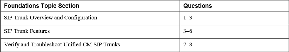
Figure 5-1 illustrates a few SIP trunk integration scenarios. As you might imagine, there is no one-size-fits-all approach to the configurations required for each type of SIP trunk integration. Some integrations require that specific parameters be enabled, and other integrations may not need those parameters at all, so you can leave them disabled. Due to the varied nature of SIP trunk integrations with Unified CM, it is very important to understand how each parameter works and, more importantly, what is being enabled or disabled.
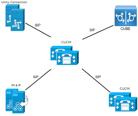
Figure 5-1 Various SIP Trunk Integrations with Unified CM
Throughout this chapter, keep in mind that Unified CM sees a SIP trunk as a device. When Unified CM receives a call for processing, it is considered an inbound call from the perspective of Unified CM and the SIP trunk which received the call is identified by Unified CM as the calling device. When Unified CM has processed a call and sends the call to a remote system, this is considered an outbound call from the perspective of Unified CM. For outbound calls over a SIP trunk, the SIP trunk is identified by Unified CM as the called device. Figure 5-2 provides an illustration to help visualize this.
Figure 5-2 Inbound Call to a Unified CM SIP Trunk Device
Figure 5-2 illustrates the following process:
Step 1. Unified CM receives an inbound SIP INVITE message from IP 1.1.1.1 on port 5060. The called number is 2000.
Step 2. From the perspective of Unified CM, the calling device is SJ_SIP_TRUNK, which has a remote destination configured for 1.1.1.1 and the SIP Trunk Security Profile for the trunk expects inbound connections on port 5060.
Step 3. Unified CM processes the call and routes the call based on the called number (2000) to the trunk in step 4, as described in Chapter 4, “Unified CM Call Routing and Digit Manipulation."
Step 4. The called device is RTP_SIP_TRUNK, with remote destination 2.2.2.2 and destination port 5060.
Step 5. Unified CM sends an outbound SIP INVITE message to 2.2.2.2 on port 5060.
Configuring a Unified CM SIP trunk involves three main configuration components:
![]()
• The SIP trunk: This is configured from the Device > Trunk menu in the Cisco Unified CM Administration web interface.
• The SIP trunk security profile: This is configured from the System > Security > SIP Trunk Security Profile menu in the Cisco Unified CM Administration web interface.
• The SIP profile: This is configured from the Device > Device Settings > SIP Profile menu in the Cisco Unified CM Administration web interface.
SIP Trunk Configuration
The SIP trunk configuration page is broken into a few sections that group together similar configuration parameters. The main sections required to understand SIP trunks for the purpose of call routing are as follows:
• Device Information: This section of the configuration page defines many of the device-specific fields for the SIP trunk. Most of these fields are found on all devices configured in Unified CM, but some fields are exclusive to a SIP trunk device.
• Call Routing Information: This section of the configuration page features many of the fields that impact call routing and digit manipulation for both inbound and outbound calls using this SIP trunk device. This section is split into two subsections, which detail the inbound and outbound settings separately.
• SIP Information: This section of the configuration page is where you define the SIP adjacencies that the Unified CM cluster should expect to communicate with via each SIP trunk. In addition, there are many other settings defined here, such as the association to the SIP profile and SIP trunk security profile.
The next few sections discuss the SIP trunk configuration parameters in these three sections.
Device Information Section
The Device Information section defines many of the fields seen on most devices in Unified CM, such as the device name, device pool, media resource group list, and others. The following sections discuss only the fields involved in SIP trunk configuration that relate to call routing and digit manipulation.
Call Classification
Several parameters in Unified CM depend on knowing whether a party is internal or external. For example, an administrator can configure Unified CM to disallow transfers between two external parties. The Call Classification field is used to determine whether the system should consider calls using the SIP trunk as internal (OnNet) calls or external (OffNet) calls; the system default is external (OffNet). This field applies to both inbound calls and outbound calls.
![]()
This classification assists with preventing toll fraud because the service parameters Block OffNet to OffNet Transfer and Drop Ad Hoc Conference depend on this classification in order to block or allow calls. The system parameter Drop Ad Hoc Conference makes use of the information if the parameter is set to When No OnNet Parties Remain in the Conference. A call is determined to fall into one of four groups: OffNet to OffNet, OffNet to OnNet, OnNet to OffNet, or OnNet to OnNet. Figure 5-3 shows these settings and the default values.
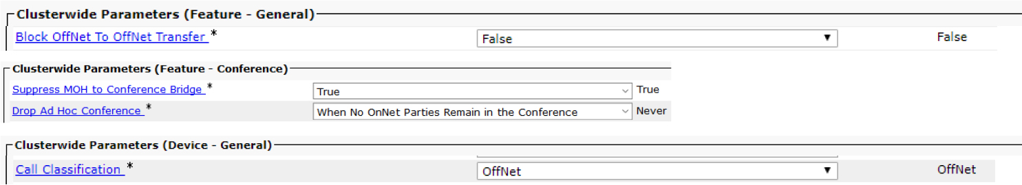
Figure 5-3 CallManager Service Parameters for Call Classification
The Call Classification parameter also affects the way an IP phone rings on inbound calls. Calls received on a trunk marked as external present a double ring on each ring cycle on some IP phone devices, while calls received on a trunk marked as internal present a single ring for each ring cycle. This allows users to audibly determine whether a call is internal or external without having to look at the phone.
AAR Group
The AAR Group setting is used for automated alternate routing (AAR), which is a topic covered in Chapter 6, “Unified CM Call Control Features.” The AAR group on the SIP trunk is only applied to inbound calls; therefore, outbound calls that do not have enough bandwidth fail.
Retry Video Call as Audio
![]()
The name of the Retry Video Call as Audio parameter just about says it all: When a video call fails, Unified CM attempts to retry the call as audio only. However, there are some small details that cannot be gleaned from the parameter name alone. For starters, this setting works only for outbound calls and does not have any impact on calls that Unified CM receives over the SIP trunk. Furthermore, this setting applies to video calls that fail due to Location Bandwidth Manager (LBM) rejecting the call based on bandwidth restrictions, as shown in Figure 5-4. This means video calls that fail because of issues such as network outages do not attempt audio only.
Note
Retry Video Call as Audio relies on call admission control (CAC), which is a topic covered in Chapter 6.
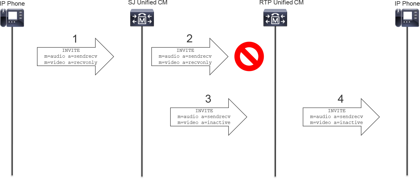
Figure 5-4 Sample Call That Starts as Video and Falls Back to Audio After Failure
Figure 5-4 illustrates the following process:
Step 1. SJ phone reaches out to SJ Unified CM to initiate a video call with RTP phone.
Step 2. When SJ Unified CM checks whether the video call can be routed over the SIP trunk to RTP Unified CM, there is not enough bandwidth for the video call and it is rejected.
Step 3. SJ Unified CM sees the SIP trunk to RTP Unified CM is configured to retry the video call as an audio-only call. Because there is enough bandwidth for the audio call, SJ Unified CM extends the audio call to RTP Unified CM.
Step 4. RTP Unified CM extends the call to the RTP phone.
Example 5-1 details what occurs in Figure 5-4 in the CallManager SDL Trace on the SJ Unified CM. It is important to understand that Step 3 occurs only when the Retry Video Call as Audio is enabled on the SIP Trunk.
Example 5-1 CallManager SDL Trace Analysis for Checked Retry Video Call as Audio
##### Step 1: Digit analysis is performed after the user at phone number 1000 calls the other user at phone number 2000. At this point the SJ Unified CM already received the SIP INVITE from the phone and is processing the call.
01814796.011 |06:39:11.254 |AppInfo  |: match(pi="2", fqcn="1000", cn="1000",plv="5", pss="", TodFilteredPss="", dd="2000",dac="0")

##### Step 2: We see this call is going to traverse the trunk which connects the SJ cluster to the RTP cluster.
01814818.003 |06:39:11.287 |AppInfo  |SMDMSharedData::findLocalDevice - Name=SIP_TRUNK_TO_RTP_CLUSTER Key=a6c9f500-89da-67e7-8521-76c611498886 isActvie=1 Pid=(1,181,5) found

##### Step 2: A little later there is an LBM request and part of the request includes bandwidth for video.
01814824.000 |06:39:11.293 |SdlSig   |LBMRegisterReq                         |active                         |LBMInterface(1,100,83,1)         |ReservationMgr(1,100,152,1)      |1,100,251,385.39^14.50.214.108^SEPC4B36ABA1B5A |[T:N-H:0,N:0,L:0,V:0,Z:0,D:0] ci=18585432 location=0 locName=Hub_None locPkid=29c5c1c4-8871-4d1e-8394-0b9181e8c54d fateShareId=sjcluster:18585432 bearerless=F videoCall=T videoCap=T videoClass=4 videoKbp=384 retryAsAudio=T ipMode=0 mediaEP=F precedence=5 nonPreemptable=F region=g711_region regState=0 XferMode=16 cacPartyState=0

##### Step 2: The request fails
01814825.002 |06:39:11.396 |AppInfo  |LBMIF: CI: 18585432 BW RSV<F 1568600405292613660 FailureRC(2) AudioRC(2) VideoRC(2) ImmersiveRC(2)

#### Step 3: This is where you see a difference in the logs depending on whether Retry Video Call as Audio is enabled. When enabled, the Unified CM attempts an audio only call. When disabled, the call will fail.
01814825.004 |06:39:11.396 |AppInfo  |LBMIF: retrying audio bw 80
01814825.005 |06:39:11.396 |AppInfo  |LBMIF: CI: 18585432 BW RSV>  dev 0xe45f3ab8 1568600405292613661 audio 80
01814825.006 |06:39:11.396 |AppInfo  |LBMIF: RSV XML> (41) 1568600405292613661 no_video_location|Hub_None A:Y,80 V:N,0 I:N,0 Force:0 Prec:5 Dpl:5

##### Step 4: Eventually the SJ Unified CM sends a SIP INVITE to the RTP Unified CM and the call moves forward.
01814858.001 |06:39:11.429 |AppInfo  |SIPTcp - wait_SdlSPISignal: Outgoing SIP TCP message to 172.18.110.91 on port 5060 index 20
[60444,NET]
INVITE sip:[email protected]:5060 SIP/2.0
From: <sip:[email protected]>;tag=20268~bbab2af3-f2b4-4a8c-a020-a2cc3e6cebe7-18585432
To: <sip:[email protected]>
Call-ID: [email protected]
CSeq: 101 INVITE
Content-Length: 575

c=IN IP4 14.50.214.108
m=audio 16466 RTP/AVP 114 101
a=sendrecv
m=video 0 RTP/AVP 31 34 96 97
a=inactive
In contrast, Example 5-2 shows what happens in the SJ CallManager SDL traces when the Retry Video Call as Audio checkbox is unchecked and video bandwidth allocation fails.
Example 5-2 CallManager SDL Trace Analysis for Unchecked Retry Video Call as Audio
##### The LBM registration request is sent with video.
01811704.000 |06:08:42.592 |SdlSig   |LBMRegisterReq                         |active                         |LBMInterface(1,100,83,1)         |ReservationMgr(1,100,152,1)      |1,100,251,385.16^14.50.214.108^SEPC4B36ABA1B5A |[T:N-H:0,N:0,L:0,V:0,Z:0,D:0] ci=18585430 location=0 locName=Hub_None locPkid=29c5c1c4-8871-4d1e-8394-0b9181e8c54d fateShareId=sjcluster:18585430 bearerless=F videoCall=T videoCap=T videoClass=4 videoKbp=384 retryAsAudio=F ipMode=0 mediaEP=F precedence=5 nonPreemptable=F region=g711_region regState=0 XferMode=16 cacPartyState=0

##### The request fails.
01811706.002 |06:08:42.646 |AppInfo  |LBMIF: CI: 18585430 BW RSV<F 1568600405292613659 FailureRC(2) AudioRC(2) VideoRC(2) ImmersiveRC(2)

#### Shortly after the failure we see a Call Control Reject Indication (CcRejInd). The failure code in the  CcRejInd is 125 which means Out of bandwidth. This is due to the video bandwidth failure coupled with the fact we are not using Retry Video Call as Audio.
01811709.000 |06:08:42.647 |SdlSig   |CcRejInd                               |idle                           |RouteListControl(1,100,173,2)    |SIPCdpc(1,100,180,27)            |1,100,251,1.43^*^*                       |[R:N-H:0,N:2,L:0,V:0,Z:0,D:0] CI=18585430 CI.branch=0  c.l=1 c.cid=8 c.cs=0 c.lc=0 c.r=0 CV=125 rejectType=1 dtmDisconn=F FDataType=0 opId=0 ssType=0 SsKey=0 invokeId=0 resultExp=F bpda=FTransparentData=null CanSupportSIPTandN=false TransId=0 AllowBitMask=0x0 UserAgentOrServer= OrigDDName=locale: 1 Name:  UnicodeName:  pi: 0 mCallerId= mCallerName= TrustRxId=T mIsMultiForkingEnabled=F mediaCause=0 CAL={v=ffffffff, m=ffffffff, tDev=F, res=F, devType=0} CAL={v=fffffff6, m=ffffffff, tDev=F, res=F, devType=0}
Call Routing Information Section
The Call Routing Information section, shown in Figure 5-5, contains many of the fields that impact call routing for both inbound and outbound calls. At the top of this section are the checkbox for Remote-Party-ID and the dropdown for Asserted-Type, which has the options P-Asserted-ID (PAI) and P-Preferred-ID (PPI). These two configuration parameters influence the delivery of these SIP headers in SIP messages using this trunk. The Asserted-Identity checkbox must be enabled to send either a PAI or PPI header specified by the Asserted-Type dropdown.
The following sections discuss the details related to inbound call routing first and then outbound call routing.
Note
Several fields in this section relate to digit manipulation and caller ID presentation rather than call routing. Chapter 4 covers digit manipulation in depth; this chapter only discusses digit manipulation in terms of how it impacts path selection in the Unified CM call routing process.

Figure 5-5 Call Routing Information Section
Inbound Calls Subsection
The settings in the Inbound Calls subsection of Call Routing Information apply only to calls received by Unified CM and associated to this particular SIP trunk, based on the source IP address and source port number. This contains the following settings for modifying call routing behavior:
![]()
• Significant Digits: This setting determines how many digits are sent to digit analysis. The precedence is given to the rightmost digits. For example, if the called number is +14085251000 and Significant Digits is set to 4, the digits 1000 are sent for processing. The impact to call routing is clear as you can see that 1000 is a different called number than the original digits received on the trunk.
• Calling Search Space: When Unified CM receives calls on a SIP trunk, the calling search space (CSS) chosen here is the one used to determine the calling privileges of the SIP trunk, given that it is the calling device from the perspective of Unified CM. Modifying the CSS applied to the trunk modifies the directory numbers or patterns that are searched by digit analysis when an inbound call is received. For more information about CSS and partitions, refer to Chapter 4.
• AAR Calling Search Space: Like the CSS previously mentioned, the AAR CSS modifies calling privileges for the trunk on inbound calls; however, this is applicable only for calls that failed because CAC determined there was no available bandwidth for the call. This CSS is applied only if there is an AAR group configured on the trunk; otherwise, AAR is not invoked. AAR groups are discussed later in this chapter.
![]()
• Prefix DN: If an administrator would like to prefix something to the called number of an inbound call, it can be done with this field. The modified called number can be seen in the CallManager SDL traces; however, the traces don’t indicate which setting performed the change, even with the CallManager Service Parameter Digit Analysis Complexity set to TranslationAndAlternatePatternAnalysis. As shown Example 5-3, the inbound SIP INVITE message with called number 1000 is processed with the dialed digits (dd) +14085251000 because the Prefix DN field is set to +1408525.
Example 5-3 CallManager SDL Traces with the Prefix DN Shown
04548625.002 |16:17:37.395 |AppInfo  |SIPTcp - wait_SdlReadRsp: Incoming SIP TCP message from 172.18.110.91 on port 43287 index 13585 with 2810 bytes:
[627563,NET]
INVITE sip:[email protected]:5060 SIP/2.0
Via: SIP/2.0/TCP 172.18.110.91:5060;branch=z9hG4bK123309736f1
From: <sip:[email protected]>;tag=94005~594cd2d2-a0cb-41cd-93ca-ed8ff9be0241-24527088
To: sip:1000@sj-cucm.ccnpcollab.lab

04548648.011 |16:17:37.438 |AppInfo  |Digit analysis: match(pi="2", fqcn="", cn="2000",plv="5", pss="partition_for_dn_1000", TodFilteredPss="partition_for_dn_1000", dd="+14085251000",dac="1")
Tip
The prefix is applied after the significant digits are gathered. This is important if the Significant Digits field is set to something other than All.
• Redirecting Diversion Header Delivery - Inbound: When a SIP call is redirected (diverted), the SIP Diversion header indicates the number of the party who redirected the call. This parameter determines whether Unified CM pays attention to the number presented in the Diversion header on calls received by the SIP trunk. This information can be used in a variety of ways. For example, it can be delivered to an IP phone to display the redirecting number information or passed on to another system, such as voicemail, to indicate the redirecting number. Figure 5-6 shows Unified CM consuming the Diversion header on a SIP trunk instead of providing it to the called party IP phone because Redirecting Diversion Header Delivery - Inbound is unchecked (which is the default for this setting). Figure 5-7 shows the same call flow but with the Redirect Diversion Header Deliver - Inbound option enabled. Unified CM sends to the IP phone an outbound INVITE message that includes the Diversion header.
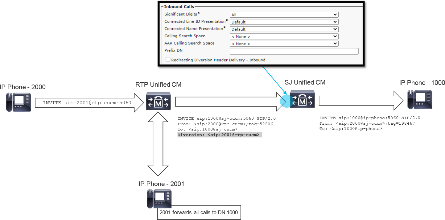
Figure 5-6 Sample Call Between Two Unified CM Endpoints That Is Redirected to a Third Unified CM Endpoint with Redirecting Diversion Header Delivery – Inbound Unselected
For a call received on a SIP trunk with Redirecting Diversion Header Delivery - Inbound enabled, the outbound SIP trunk must also have the Redirecting Diversion Header Delivery - Outbound option enabled in order for the redirecting information to be passed through from one trunk to another. Outbound Diversion header delivery is discussed later in this chapter.
Note
The diverted number is sometimes called the redirecting party number or original called party number.
This setting is very important for call flows that include multiple Unified CM clusters and integrations with service providers or other Unified CM applications.
Figure 5-6 illustrates the following process:
Step 1. The RTP phone with DN 2000 calls the RTP phone with DN 2001.
Step 2. RTP Unified CM attempts to route the call to the RTP phone with DN 2001; however, DN 2001 is configured to forward calls to the SJ phone with DN 1000.
Step 3. RTP Unified CM extends the call to SJ Unified CM, and you can see the Diversion header in the SIP INVITE message.
Step 4. SJ Unified CM extends the call to the SJ phone, and there is no Diversion header because the inbound trunk on the SJ Unified CM did not have the box checked for Redirecting Diversion Header Delivery - Inbound.
Figure 5-7 shows the Diversion header in the SIP INVITE message sent from SJ Unified CM to the SJ phone with extension 1000.

Figure 5-7 Sample Call Between Two Unified CM Endpoints That Is Redirected to a Third Unified CM Endpoint with Redirecting Diversion Header Delivery – Inbound Selected
Incoming Called Party Settings Subsection
![]()
This section of the SIP trunk configuration allows you to modify the called number by prefixing and stripping digits; therefore, this section impacts call routing as the called number is modified and before it is sent to digit analysis for processing. When a value other than Default is defined in the Prefix section, Unified CM allows the modification of the Strip Digits section. The Prefix section is self-explanatory and operates similarly to the Prefix DN parameter described earlier in this section.
Next let’s examine the Strip Digits section. Which digits will be stripped? The leftmost digit(s), also known as the most significant digit(s), will be stripped when there is a value other than 0 configured. Consider the configuration shown for the Incoming Called Party Settings subsection in Figure 5-8.

Figure 5-8 Configuration of the Incoming Called Party Settings
In Figure 5-8 you can see the Calling Search Space parameter and Use Device Pool CSS checkbox. These two settings influence the lookup of called party transformations based on the configured CSS and partition combination. Use Device Pool CSS is checked by default, and as you would expect, the Device Pool setting for the Called Party Transformation CSS is used. To override what is configured in the device pool with a SIP trunk–specific CSS, you must ensure that Use Device Pool CSS is unchecked and then select the appropriate CSS from the Calling Search Space drop down menu. It is important to remember that the transformation pattern lookup and subsequent changes are applied after the strip digits and prefix operations are applied in this section of the configuration. For more information about calling and called party transformations, refer to Chapter 4.
Note
The configurations in the SIP trunk Incoming Called Party Settings subsection override the prefix configured on the device pool Incoming Called Party Settings.
Figure 5-9 illustrates the following events:
Step 1. The RTP phone at 2000 sends an INVITE message to RTP Unified CM with called number 9900.
Step 2. RTP Unified CM extends the call to SJ Unified CM with called number 9900 (that is, To: <sip:[email protected]>).
Step 3. Because the SIP trunk has Strip Digits set to 2, SJ Unified CM strips the two leftmost digits from the called number, making the called number 00.
Step 4. Because the SIP trunk has Prefix set to 10, SJ Unified CM prefixes 10 to the modified called number 00, making the called number 1000.
Step 5. SJ Unified CM processes the call with called number 1000 and extends the call to the SJ phone at 1000.

Figure 5-9 Sample Call Between Two Unified CM Endpoints
Example 5-4 shows the CallManager SDL trace analysis from the SJ Unified CM for this example.
Example 5-4 CallManager SDL Traces for Figure 5-9
##### First, we see the SIP INVITE come in with a To header which shows 9900 as the called number.
02983405.002 |11:29:47.139 |AppInfo  |SIPTcp - wait_SdlReadRsp: Incoming SIP TCP message from 172.18.110.91 on port 38032 index 7630 with 2810 bytes:
[401216,NET]
INVITE sip:[email protected]:5060 SIP/2.0
Via: SIP/2.0/TCP 172.18.110.91:5060;branch=z9hG4bK10262b753c8
From: <sip:[email protected]>;tag=53066~594cd2d2-a0cb-41cd-93ca-ed8ff9be0241-24527078
To: <sip:[email protected]>

##### Later we see the call information modified by the SIPCdpc process. The modifications are in line with the configurations on the SIP trunk and the updated number is 1000.
02983419.028 |11:29:47.143 |AppInfo  |SIPCdpc(0) - globalizeCdpn: SPROC globalizeCdpn calledunknown CSS = , unknownPrefix=10, unknownStrip=2
02983419.029 |11:29:47.143 |AppInfo  |SPROC :: stripAndPrependCdpnDigits - The number 00 is prepended with prefix 10, updated number=1000

##### When the call is sent to the DigitAnalysis process for call routing, we can see the dialed digits listed as 1000
02983428.007 |11:29:47.154 |AppInfo  |Digit analysis: match(pi="2", fqcn="", cn="2000",plv="5", pss="partition_for_dn_1000", TodFilteredPss="partition_for_dn_1000", dd="1000",dac="1")

##### Eventually the INVITE is sent to the SJ phone at 1000
02983469.001 |11:29:47.202 |AppInfo  |SIPTcp - wait_SdlSPISignal: Outgoing SIP TCP message to 14.50.214.108 on port 50770 index 4934
[401218,NET]
INVITE sip:[email protected]:50770;transport=tcp SIP/2.0
Via: SIP/2.0/TCP 172.18.110.61:5060;branch=z9hG4bK2d49b2f1c1fbc
From: <sip:[email protected]>;tag=200797~bbab2af3-f2b4-4a8c-a020-a2cc3e6cebe7-24527159
To: <sip:[email protected]>
Note
The Incoming Calling Party Settings subsection operates under the same logic as the Incoming Called Party Settings subsection regarding the Prefix and Strip Digits operations and thus has been omitted from this text for the sake of brevity.
Outbound Calls Subsection
None of the settings in the Outbound Calls subsection, shown in Figure 5-10, relate to call routing. Instead, they all pertain to number presentation or call information of some sort. Many of these caller ID–related settings are discussed in Chapter 4, so they are not discussed in this chapter.

Figure 5-10 Sample Configuration of the Outbound Calls Subsection
Redirecting Diversion Header Delivery - Outbound
One setting that is crucial to the success of SIP integrations with voicemail systems such as Cisco Unity Connection (CUC) is Redirecting Diversion Header Delivery - Outbound. When a call is forwarded to a voicemail system, it is important to know if the call is placed directly to the voicemail system or redirected to the voicemail system. If the call is redirected, the voicemail system needs to know the original called number. This allows the voicemail system to identify the proper voicemail box for leaving a message. When the setting is enabled on a SIP trunk, Unified CM adds a SIP Diversion header in the outbound INVITE message for redirected calls. In the following Diversion header, for example, you can see that extension 1001 was dialed, and the call was diverted from there:
Diversion: <sip:[email protected]>;reason=no-answer;privacy=off;screen=yes
As indicated in the previous section, when a call is between an inbound SIP trunk and an outbound SIP trunk, in order to properly pass a Diversion header between the two call legs, both the Redirecting Diversion Header Delivery - Inbound and Redirecting Diversion Header Delivery - Outbound settings must be enabled.
SIP Information Section
The SIP Information section of the SIP trunk configuration is where you define the SIP adjacencies that the Unified CM cluster uses to communicate with by using this trunk. In addition, there are many other settings defined here, such as the association to the SIP profile and SIP trunk security profile. Figure 5-11 provides an at-a-glance view of what can be configured in this section. The following sections discuss some of these parameters.

Figure 5-11 SIP Information Section of the SIP Trunk Configuration Page
Destination
The Destination subsection of the SIP trunk configuration is where you define the SIP peers with which the Unified CM cluster will communicate with via the trunk. Figure 5-12 shows the Destination subsection of the SIP Information section.

Figure 5-12 Sample Configuration for the SIP Trunk Destination
![]()
The Destination Address field is where you specify the remote peer. There are three valid formats that can be entered in the Destination Address field:
• IPv4 address
• Fully qualified domain name (FQDN)
• DNS SRV record
The Destination Address Is an SRV checkbox must be selected only when the value provided in the Destination Address field is a DNS SRV record. If the remote peer supports IPv6, the address is entered in the Destination Address IPv6 field. Some devices support IPv4 as well as IPv6, and in those scenarios, it is recommended to configure the Destination Address field and the Destination Address IPv6 field.
You can add up to 16 Destinations by clicking the plus icon to the right of the Duration column. When multiple destinations exist on a SIP trunk, Unified CM handles load balancing of calls in a round-robin fashion. If you want to route calls to the remote destinations using a different distribution algorithm, for example top down, you might want to add individual trunks for each destination to control call routing decisions by using route lists and route groups as described in Chapter 4. When a DNS SRV is selected, only a single DNS SRV record can be configured. If there are any extra destination rows added with the plus icon, they are grayed out and unconfigurable.
The last configuration field in this section is Destination Port. Typically, this is set to 5060; however, if SIP over TLS is configured to enable encrypted signaling, it may be set to 5061. However, it all depends on what the remote peer is configured to use. For example, if the remote peer is listening on 5066, the Destination Port setting on the SIP trunk needs to reflect 5066. You should configure the port number to match the listening port number of the far-end device.
If the remote service to which this SIP trunk connects supports multiple redundant servers for terminating or originating calls through this SIP trunk, the plus icon located all the way to the right is used to add additional entries. If the Destination Address Is an SRV checkbox is checked, the plus icon is disabled, and only one destination address can be specified for the trunk, and Unified CM determines the list of peers from the DNS SRV record.
Note
If the remote peer is a Unified CM cluster, and a DNS SRV is configured in the Destination Address field, it is important that the DNS SRV record include all nodes on the remote cluster that are running the CallManager service.
Note
The Status, Status Reason, and Duration columns display N/A by default. The information in these columns is dependent on whether SIP OPTIONS ping is enabled on the SIP profile in use. SIP OPTIONS ping is covered in more detail later in this chapter, along with other SIP profile parameters.
While the Destination section allows you to define the remote endpoint information for where Unified CM will send outbound calls, this section is also relevant for inbound calls. Upon receiving a SIP INVITE message, the Unified CM node checks the source of the call against all locally available SIP trunks for a configured destination address that matches the source address. If a destination configuration matching the source of the inbound INVITE message is found, the call uses that particular SIP trunk as the incoming device, and the settings for incoming calls apply. If there is no locally available SIP trunk with a configured destination matching the inbound INVITE message, Unified CM rejects the call with a 503 Service Unavailable error and includes a Warning header with the text “Unable to find a device handler for the request received on port 5060 from 172.18.110.88” (as shown in Example 5-5). This IP address will be what Unified CM was checking SIP trunk destinations for.
Note
The listening port is the Incoming Port defined on the SIP Trunk Security Profile as described in the upcoming sections of this chapter.
Example 5-5 Unified CM 503 Service Unavailable for Inbound Trunk Selection Based on IP:Port
SIP/2.0 503 Service Unavailable
Via: SIP/2.0/UDP 172.18.110.88:5060;branch=z9hG4bK-24292-1-0
From: <sip:[email protected]:5060>;tag=24292SIPpTag001
To: <sip:[email protected]:5060>;tag=1811051381
Date: Thu, 23 Jul 2020 16:23:53 GMT
Call-ID: [email protected]
CSeq: 1 INVITE
Allow-Events: presence
Warning: 399 cucm-12-5 “Unable to find a device handler for the request received on port 5060 from 172.18.110.88"
Content-Length: 0
Rerouting Calling Search Space
As previously discussed, the CSS configured in the Device Information section is used to determine which patterns are searched when a call is received on the trunk; however, a different CSS is referenced when a call is redirected using the SIP trunk. That CSS is the Rerouting calling search space. The Rerouting Calling Search Space setting is commonly used when the remote peer sends Unified CM a SIP REFER message. The Rerouting Calling Search Space setting may also be used if an INVITE message contains a Replaces header or if a 3xx Redirection response is received for a call.
The Rerouting Calling Search Space setting is required when CUC is integrated using SIP and there is a call handler that transfers calls back to Unified CM using the CUC configuration option Release to Switch. In this scenario, a SIP REFER message is used as the transfer method by the CUC call handler. Similarly, the Rerouting Calling Search Space setting is also used when Unified CM is integrated with CMS, and the Move Participants feature is invoked to migrate a conference participant from a conference on one call bridge to a conference on another call bridge. In the CMS scenario, Unified CM receives a SIP INVITE message with a Replaces header, which triggers the Rerouting calling search space lookup.
Normalization Script
The Normalization Script settings allow an administrator to apply one of the many built-in SIP normalization scripts to a SIP trunk. These scripts utilize the Lua programming language to modify aspects of inbound or outbound SIP messages across a trunk. In one common scenario, when Unified CM integrates with CMS, the built-in cisco-meeting-server-interop SIP normalization script should be applied to perform changes to the SIP message, which allow CMS and Unified CM to function properly. Similarly, there are other scripts which can be found under Device > Device Settings > SIP Normalization Script. You can also configure a custom SIP normalization script and apply it to the SIP trunk. The Enable Trace checkbox in this section can be useful for printing SIP normalization logs in Unified CM SDL traces. The topic of custom SIP normalization scripts is beyond the scope of the CLACCM 300-815 exam. For more information on SIP normalization on Unified CM using Lua, visit https://developer.cisco.com/site/uc-manager-sip/documents/sip_normalization_trans/.
SIP Trunk Security Profile Configuration
The SIP Trunk Security Profile is a mandatory field on the SIP trunk configuration page. This profile functions similarly to device pools: Just as a device pool allows several settings to be applied as a single field on the configuration page of a device, the SIP Trunk Security Profile groups security settings related to SIP trunks. All the security settings in the profile are applied to the trunk when the profile is defined on the trunk.
Although there are default SIP Trunk Security Profiles which can be applied to a SIP Trunk, administrators often create a new SIP Trunk security profile to apply custom settings. To configure a SIP trunk security profile, navigate to System > Security > SIP Trunk Security Profile. When the Find and List SIP Trunk Security Profiles page loads, click Add New. At this point, you reach the SIP Trunk Security Profile Configuration page, which is shown in Figure 5-13. This is where you specify the security parameters you want to apply on SIP trunks.

Figure 5-13 Creating a Trunk Security Profile Called Non Secure SIP Trunk Profile
The Name field is mandatory, and the name specified here is what appears in the dropdown menu for SIP Trunk Security Profile on the trunk configuration page. The other main fields and options for SIP trunk security profiles are discussed in the following sections.
Incoming Transport Type
There are two options for the Incoming Transport Type field. The TCP+UDP option is the only possible choice if Device Security Mode is set to Non Secure and the TLS option is the only choice possible when the Device Security Mode is set to Encrypted or Authenticated. This section simply modifies the OSI Model Layer 4 transport protocol the SIP trunk expects inbound SIP requests to use.
Outgoing Transport Type
The outgoing transport type is the same as the incoming transport type; however, the Outgoing Transport Type parameter determines what transport protocol Unified CM uses when sending calls to a remote peer. The three option are UDP, TCP (default), and TLS. This field may be used in troubleshooting when UDP is in use and the remote device is not replying to SIP messages or when TCP is selected and the TCP SYN message is not being acknowledged. In such a case, you can toggle this field to see if a network device is blocking one transport protocol or the other. TLS is beyond the scope of the CLACCM 300-815 exam so this chapter will not cover TLS in depth.
Incoming Port
![]()
The Incoming Port parameter defines the SIP listening port for inbound SIP traffic from remote peers. The default value for this parameter is 5060 for insecure TCP or UDP traffic; for secure TLS SIP traffic, Unified CM automatically changes the Incoming Port to 5061. This parameter is used in conjunction with the destination address specified on the SIP trunk in order to accept or reject inbound calls on the trunk. Do not confuse the incoming port with the destination port configured on the trunk as the destination port is used for outbound calls while the Incoming Port is used for inbound calls. If the remote peer wants to send SIP signaling using port 5063, then the Incoming Port needs to reflect port 5063 or the inbound call will fail.
The Incoming Port parameter is reflected as the port sent in SIP headers for outbound calls. Unified CM administrators might change the Incoming Port parameter to influence the peer’s responses, such as 100 Trying or 200 OK in response to Unified CM sending a SIP INVITE message. For example, when the incoming port is defined as 5065, the SIP Via and Contact headers in an INVITE message sent by Unified CM show port 5065, as indicated in the following output:
INVITE sip:[email protected]:5060 SIP/2.0
Via: SIP/2.0/UDP 10.10.10.12:5065;branch=z9hG4bK12a9341f7ac6ec
Contact: <sip:[email protected]:5065>
Accept Unsolicited Notification
Two common use cases for the Accept Unsolicited Notification checkbox are DTMF and message waiting indication (MWI). For example, when Cisco Unity Connection (CUC) is integrated with Unified CM using SIP, the MWI update is sent using a SIP NOTIFY message after the caller leaves a message and ends the call. For example, at the bottom of Figure 5-14, the original call has ended, and a SIP NOTIFY message is observed. There is no explicit subscription via SIP SUBSCRIBE, and the SIP message was not part of the original SIP dialog—hence the unsolicited nature of this message. If the Accept Unsolicited Notification checkbox is not selected, unsolicited SIP NOTIFY messages are rejected with a SIP 403 Forbidden error.
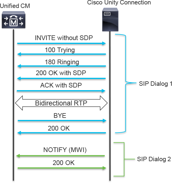
Figure 5-14 Sample Call to Cisco Unity Connection with Subsequent Unsolicited SIP NOTIFY for MWI
Accept Replaces Header
As mentioned earlier, Unified CM leverages the Rerouting Calling Search Space parameter when an INVITE with a Replaces header is received on a SIP trunk. This is commonly seen when Unified CM integrates with a CMS cluster that is using the Move Participants feature. The SIP Replaces header may also be used by CMS for general load balancing of calls across the CMS cluster when using the Call Bridge Groups feature. For these two features to work properly, the Accept Replaces Header setting should be enabled on the SIP trunk security profile.
SIP Profile Information Configurations
The SIP Profile Information section, like the SIP Trunk Security Profile Information section, enables you to perform configurations in a templatized fashion. All the settings in a SIP profile are applied to the trunk when the profile is defined on the trunk. Rather than specifying settings on each trunk, you put them in the profile and then apply the profile to the appropriate trunks.
Much like the SIP Trunk Security Profile, there are default SIP profiles that can be applied to a trunk. However, many Unified CM administrators create new SIP profile’s with custom settings enabled or disabled based on their requirements for the SIP trunk. To configure a SIP profile, navigate to Device > Device Settings > SIP Profile. When the Find and List SIP Profiles page loads, click Add New. At this point, you reach the SIP Profile Configuration page, which is shown in Figure 5-15. There are many options on this page, and this section covers a few of them.

Figure 5-15 Standard SIP Profile
Keep in mind that SIP profiles are used by both SIP IP phones and SIP trunks, and there are different configuration sections for each. This section focuses on the trunk-specific configuration, using the settings displayed in Figure 5-16. Although early offer support for voice and video calls and SIP OPTIONS ping are shown in the figure, those configuration settings are covered later in the chapter. There are also many other features within the SIP Profile that are not discussed in this chapter as they are beyond the scope of the CLACCM 300-815 exam.
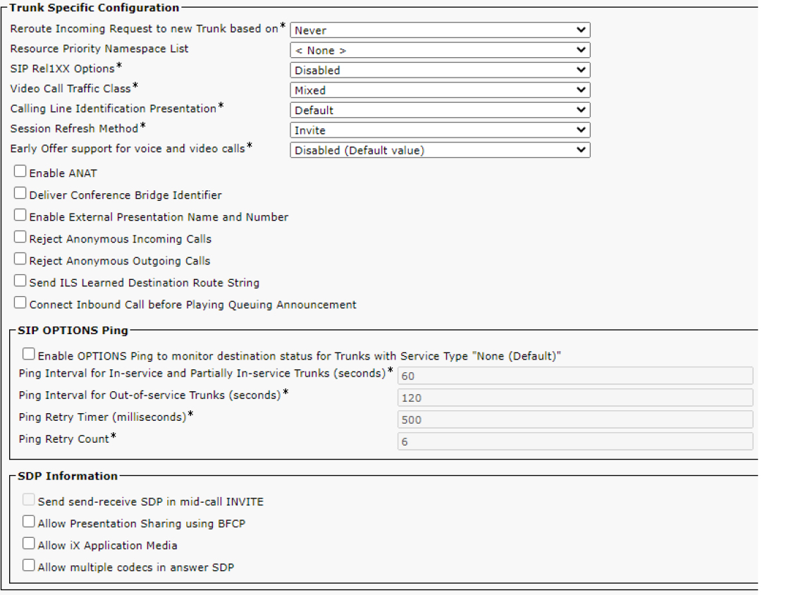
Figure 5-16 Trunk-Specific Configuration Portion of the Unified CM SIP Profile
SIP Rel1XX Options
The SIP Rel1XX Options field is required and pertains to SIP provisional responses. For more information on SIP PRACK operation, see Chapter 9, “CUBE Interworking Features.” This chapter covers PRACK in terms of the SIP trunk configuration and how this setting affects PRACK on Unified CM SIP trunks. There are three options for this field:
• Disabled: This means Rel1XX is not enabled.
• Send PRACK if 1xx Contains SDP: When this option is used, PRACK is sent only when there is SDP present in the 1XX message.
• Send PRACK for All 1xx Messages: This option indicates that every 1XX message is acknowledged with a PRACK; however, the SIP Rel1XX Options field does not apply to the 100 Trying message, as it is forbidden by the RFC 3262 to use PRACK for the 100 Trying message.
If either of the Send PRACK options are enabled, PRACK is used on inbound calls when Unified CM sends a 1xx message other than a 100 Trying provisional response; in addition, Unified CM includes the 100rel header in its own egress SIP INVITE messages when traversing a trunk which is associated with a SIP profile that has PRACK enabled; therefore, indicating to the far end that PRACK is supported for the outbound call. The following is a sample SIP Supported header, which indicates support for reliable provisional responses (100rel):
Supported: 100rel,timer,resource-priority,replaces
Tip
If the remote peer sends SIP signaling that doesn’t include 100rel in the Supported SIP header, Unified CM does not send a PRACK message, regardless of which SIP Rel1XX Options setting is selected.
Session Refresh Method
Because SIP is a peer-to-peer protocol, it is important to have a way to determine whether any given session is still alive. The session status is maintained with an occasional refresh message. When a refresh is late or nonexistent, the session is deemed no longer active, and a BYE is sent to terminate the session. There are two options for this field: INVITE and UPDATE. The default option is INVITE, which means sessions are refreshed by sending a re-INVITE; the UPDATE option results in sessions being refreshed using a SIP UPDATE message.
Note
Chapter 9 covers Session Refresh in-depth.
Reject Anonymous Incoming Calls
![]()
The Reject Anonymous Incoming Calls setting is self-explanatory: If a call is received on the trunk, and the calling party is anonymous, the call is rejected. Example 5-6 shows CallManager SDL trace analysis for a situation in which a call is rejected because of this parameter. Unified CM receives a SIP INVITE message with a From header containing anonymous as the user ID. Next, the SIP process sends a 433 Anonymity Disallowed message to reject the call.
Example 5-6 CallManager SDL Trace Analysis for Call Rejected Based on Anonymous Caller ID
##### The SIP trunk receives an INVITE which is from an anonymous source.
01563228.002 |14:46:30.299 |AppInfo  |SIPTcp - wait_SdlReadRsp: Incoming SIP TCP message from 172.18.110.91 on port 33615 index 12 with 2904 bytes:
[213830,NET]
INVITE sip:[email protected]:5060 SIP/2.0
Via: SIP/2.0/TCP 172.18.110.91:5060;branch=z9hG4bK1d1450ac71
From: “Anonymous” <sip:anonymous@anonymous.invalid>;tag=9112~594cd2d2-a0cb-41cd-93ca-ed8ff9be0241-24527014
To: <sip:[email protected]>
Call-ID: [email protected]
User-Agent: Cisco-CUCM12.5
CSeq: 101 INVITE
X-Cisco-Presentation: “anonymous” <sip:[email protected]>;party=internal
P-Asserted-Identity: <sip:172.18.110.91>
Privacy: id
Remote-Party-ID: <sip:172.18.110.91>;party=calling;screen=yes;privacy=full
Contact: <sip:172.18.110.91:5060;transport=tcp>;video;audio;+u.sip!devicename.ccm.cisco.com="SEPC4B36ABACA23"

##### After the parameter is checked, the server prints a log entry stating we need to reject the call due to anonymous calling party.
01563242.016 |14:46:30.302 |AppInfo  |SIPCdpc(9) - processSIPSetupMsg: Incoming anonymous call is rejected with reason: Caller's Number is not available value 1

##### The response to the INVITE is seen below and it is a SIP 433 Anonymity Disallowed. We also see there is a reason code 21 associated with the failed call.
01563244.001 |14:46:30.302 |AppInfo  |SIPTcp - wait_SdlSPISignal: Outgoing SIP TCP message to 172.18.110.91 on port 33615 index 12
[213832,NET]
SIP/2.0 433 Anonymity Disallowed
Via: SIP/2.0/TCP 172.18.110.91:5060;branch=z9hG4bK1d1450ac71
From: “Anonymous” <sip:[email protected]>;tag=9112~594cd2d2-a0cb-41cd-93ca-ed8ff9be0241-24527014
To: <sip:[email protected]>;tag=102437~bbab2af3-f2b4-4a8c-a020-a2cc3e6cebe7-24527079
Date: Mon, 02 Dec 2019 19:46:30 GMT
Call-ID: [email protected]
CSeq: 101 INVITE
Server: Cisco-CUCM12.5
Reason: Q.850; cause=21
Reject Anonymous Outgoing Calls
The Reject Anonymous Outgoing Calls setting is like Reject Anonymous Incoming Calls, but there are two differences. The first difference is in the direction of the call. For the Reject Anonymous Outgoing Calls parameter to be applicable, the call must be leaving Unified CM using a SIP trunk with this parameter set. The other difference is found in the CallManager SDL traces. For the outbound call, Example 5-7 shows the message shown in the traces; you do not see this message for the inbound call sample in Example 5-6.
Example 5-7 A Sample Snippet of CallManager SDL Traces Detailing a Call Rejection Based on Anonymous Caller ID
01575230.003 |15:21:21.482 |AppInfo |SIPCdpc(19) - null0_CcSetupReq: Call from anonymous caller is rejected reason=2
SIP Trunk Features
Up to this point, the chapter has discussed different SIP trunk configurations that impact call routing and digit manipulation. The following sections discuss some of the settings on the SIP trunk configuration page that affect various aspects of Unified CM, such as SIP interworking, media processing, and SIP trunk availability both in Unified CM and with remote devices.
SIP Early Offer Versus SIP Delayed Offer
![]()
While the concepts of SIP early offer and delayed offer are covered in Chapter 2, “VoIP Protocols: SIP and H.323,” this section discusses early offer and delayed offer on Unified CM SIP trunks and how to influence the type of offer sent by Unified CM. By default, Unified CM uses delayed offer when sending egress SIP INVITE messages. In order to modify this behavior, it is necessary to change the configuration of early offer support for voice and video calls on the SIP profile used by the SIP trunk.
There are three options for the field Early Offer support for voice and video calls:
• Disabled (Default Value): INVITE messages sent from the Unified CM to a remote peer do not contain SDP.
• Best Effort (No MTP Inserted): An early offer is sent via the SIP trunk only if the media information of the calling party is known at the time the call is placed. An example of this behavior is illustrated in Figure 5-17, which shows two different scenarios that are possible when this parameter is configured with this setting. In the first scenario, the inbound SIP INVITE contains SDP, which means Unified CM can send an egress, early offer SIP INVITE message. In the second scenario, where a delayed offer SIP INVITE is received by Unified CM, the egress SIP INVITE sent by Unified CM also uses delayed offer because Unified CM does not know the media information of the calling party.

Figure 5-17 Using Best Effort (No MTP Inserted) with a Unified CM SIP Trunk
• Mandatory (Insert MTP if Needed): With this setting, an early offer is sent for all outbound calls. Furthermore, a media termination point (MTP) is inserted if the media information for the calling party is unknown. Figure 5-18 illustrates a similar scenario to the one shown in Figure 5-17 but with Mandatory (Insert MTP if Needed) enabled. In the first call shown in Figure 5-18, early offer is received on the ingress INVITE message, and thus an INVITE message with an early offer is sent. However, in the second call depicted in Figure 5-18, the following process occurs:
1. No SDP or media information is received with the ingress INVITE message.
2. Unified CM needs to allocate an MTP; therefore, Unified CM pulls in an available MTP which happens to be on a voice gateway.
3. The egress SIP INVITE message is sent as early offer with SDP. Unified CM adds the MTP IP address and port number to the SDP for of the egress SIP INVITE message.
4. RTP is established between the calling party and the MTP, as well as between the called party and the MTP.
Note
Unified CM has local, software MTPs that can be used in place of the MTP on the voice gateway.

Figure 5-18 Using Mandatory (Insert MTP if Needed) with a Unified CM SIP Trunk
SIP OPTIONS Ping
Unified CM can utilize SIP OPTIONS messages known as SIP OPTIONS Ping or SIP Keepalive to perform out-of-dialog (OOD) SIP reachability testing. This reachability check allows Unified CM to determine whether the remote peer defined on a SIP trunk is active and reachable. If a destination does not respond to a SIP OPTIONS message, it is considered down and Unified CM will not attempt routing calls to the destination. Once the destination responds to the SIP OPTIONS messages, Unified CM will then attempt to extend calls to the destination when appropriate. This reduces the failover time when there are multiple SIP trunks in a route group. To be considered down, or “out of service,” one of the following must occur:
• If TCP or TLS is used, the TCP socket is not established.
• If UDP is used, no response is received to multiple transmissions of a SIP OPTION message.
• A SIP 503 Service Unavailable response is received.
• A SIP 408 Timeout response is received.
All other responses to a SIP OPTIONS message are considered valid, and the trunk remains up and in service. Note that each Unified CM server is responsible for tracking its own reachability of the remote peer. It is possible for Unified CM Server A to send a SIP OPTIONS message, receive a 200 OK message, and mark the trunk as being in service locally; however, for one reason or another, Unified CM Server B may send a SIP OPTIONS message but never receive a response. Unified CM Server B then marks the trunk down and out of service. In this scenario, only Unified CM Server A can process inbound and outbound calls because it is the only server with the SIP trunk marked as in service. While Unified CM Server B might process a call intended for the remote peer, Unified CM Server B will not extend the call to the remote peer due to reachability issues. The call will not be handed over to Unified CM Server A and the call will fail because the remote peer is not reachable from the Unified CM node that processed the call.
Unified CM does not send SIP OPTIONS pings by default. This is a feature that needs to be enabled via the SIP profile assigned to a SIP trunk (see Figure 5-19). To enable OPTIONS pings, simply enable the SIP OPTIONS Ping checkbox; as shown in Figure 5-19, selecting this checkbox enables the time intervals and retries counters for modification.

Figure 5-19 Unified CM SIP Profile Configuration for SIP OPTIONS Ping
![]()
When SIP OPTIONS messages are enabled on a SIP profile assigned to a SIP trunk, the SIP Trunk Status column found on the Device > Trunk page (shown in Figure 5-20) is populated with one of three values and the SIP Trunk Duration is populated with total time the trunk has been in that status:
• Full service: All remote destinations are reachable or have returned SIP responses indicating that they are up and accepting connections from Unified CM.
• Partial Service: At least one destination peer has failed the reachability check defined earlier in this section. Partial status is from the perspective of the current Unified CM node.
• No Service: None of the destination peers are reachable, or they have failed one of the checks defined earlier in this section.

Figure 5-20 SIP Trunk Status Reported Through the SIP OPTIONS Message
Tip
If SIP OPTIONS messages are not enabled, the SIP Trunk Status column on the Device > Trunk page indicates Unknown OPTIONS Ping not Enabled.
If a trunk is not in full service, a status reason is usually shown on the SIP trunk page, next to the problematic destination address. The reason can be one of three values:
• local=1: Request timeout
• local=2: Local SIP stack is not able to create a socket connection with the remote peer
• local=3: DNS query failed
Figure 5-20 details two different statuses for SIP trunks. The first is a SIP trunk (SIP_OPTIONS_BAD) with a status of No Service, and the second is the SIP trunk (SIP_OPTIONS_GOOD) that is in full service. The first part of this figure shows both SIP trunks in a table that has SIP Trunk Status and SIP Trunk Duration columns. The two portions at the bottom of the figure show Destination sections for both SIP trunks. The values under Status, Status Reason, and Duration are listed next to the destination address and port that was polled with the SIP OPTIONS message.
Media Termination Point Required
Figure 5-21 shows the SIP trunk configuration page. When the Media Termination Point Required box on this page is checked, an MTP is allocated for each outbound call. The use of the word Required in the name implies that calls will fail if an MTP is not available; however, this is not completely true. A Cisco CallManager service parameter determines whether the call should fail when the MTP is not available: Fail Call Over SIP Trunk if MTP Allocation Fails. The default setting for this parameter is False, which causes Unified CM to attempt call routing in a scenario where no MTP can be inserted.

Figure 5-21 Media Termination Point Required
The MTP Required field is sometimes recommended as a solution to a variety of issues; however, it is not an ideal approach and is typically a workaround to some other issue that can be solved through other mechanisms. It is best to let the Unified CM server dynamically insert an MTP into a call rather than allocate an MTP for each outbound call. When this field is enabled, media resources are needlessly consumed. Furthermore, if an outbound fax call uses a trunk that requires an MTP, the fax call is negatively impacted by the presence of the media resource.
Note
The allocation logic of media resources by Unified CM is beyond the scope of the CLACCM 300-815 exam.
Run On All Active Unified CM Nodes
The Run On All Active Unified CM Nodes setting enables each node in a cluster to process calls for a SIP trunk directly rather than needing to potentially contact another node in the cluster in order to make use of a SIP trunk. When the Run On All Active Unified CM Nodes setting is disabled, calls are subject to an additional point of failure, and the SIP trunk process runs only on nodes that are in the Unified CM group of the device pool configured on the SIP trunk. This means that only some nodes in the cluster accept calls for this SIP trunk. In addition, outbound calls originate only from the nodes in the Unified CM group. Figure 5-22 shows how a call is processed when this feature is not enabled.

Figure 5-22 Sample Call Without Run on All Active CM Nodes Enabled
![]()
In contrast, when the Run On All Active Unified CM Nodes setting is enabled, there is additional redundancy and less intracluster traffic across the network, as shown in Figure 5-23. This setting also simplifies troubleshooting because all call processing occurs on a single server in the cluster, reducing the number of trace files to review when diagnosing an issue.

Figure 5-23 Sample Call with Run on All Active CM Nodes Enabled
Note
Note that the Run on All Active CM Nodes setting applies only to Unified CM nodes running the Cisco CallManager service.
Verify and Troubleshoot Unified CM SIP Trunks
Whether in the lab or on the job, at some point, you will need to troubleshoot a Unified CM SIP trunk. Common scenarios for both new and existing SIP trunk integrations include the following:
• A SIP trunk is down or out of service.
• Inbound or outbound calls across a specific SIP trunk fail.
• Supplementary service features across a SIP trunk fail.
• Presentation of Caller ID or SIP headers for calls across a SIP trunk fail to show.
• General call routing issues occur, with the SIP trunk as the calling or called device.
Trace analysis methods discussed in Chapter 4 are applicable to troubleshooting the problems on a SIP trunk; however, they are not repeated in this section. The following sections detail a few additional methods you can use to help scope and identify problems involving Unified CM SIP trunks.
Packet Captures (PCAPs)
As when troubleshooting most other issues on a network, it is often useful to get packet captures when troubleshooting a SIP trunk. When a trunk is configured to send SIP signaling via TCP, you can use a packet capture to confirm the TCP handshake is being established correctly and view the SIP signaling being sent/received between Unified CM and a remote SIP user agent. When SIP signaling is sent via UDP, it is still possible to see the messages in the pcap, including UDP SIP messages being sent repeatedly if they are not responded to.
The commands shown in Example 5-8 enable a packet capture from the Unified CM CLI. This packet capture is enabled on a node-by-node basis; therefore, the command needs to be executed in the CLI of each Unified CM node when gathering packet captures from multiple nodes. To stop a packet capture, simply enter a break command such as Ctrl+C. If the packet capture file fills up, the capture automatically stops unless you are using the capture-rotate command, which rotates packet captures to a new file. The first command in Example 5-8 will capture packets of any size, for all hosts, on all ports, for up to 1000 packets, and saves the data into a file named cucmpcap while the second command shows available options.
Example 5-8 Packet Capture Commands from Unified CM CLI
admin: utils network capture size all count 1000 file cucmpcap

admin: utils network capture-rotate ?
Syntax:
utils network capture-rotate [options]
options  mandatory   file fname
options  optional    size bytes,sizePerFile megabytes, maxFiles num,src addr,dest addr,port num,host protocol addr
Example 5-9 demonstrates how to enable a packet capture specifically for SIP traffic that is sent to, or received from, a specific IP address. This is useful when troubleshooting a specific SIP trunk because you can use the IP address of the remote device for the trunk. The command in Example 5-9 captures up to 1000 packets of any size that are sent to, or received from, 192.168.120.5 on port 5060 and saves the data into a file named filteredcucmpcap.
Example 5-9 Filtered Packet Capture Command
admin: utils network capture size all count 1000 host ip 192.168.120.5 port 5060 file filteredcucmpcap

Executing command with options:
 size=ALL                count=1000              interface=eth0
 src=                    dest=                   port=5060
 ip=192.168.120.5
OPTIONS Ping
As previously discussed, the OPTIONS ping feature enables Unified CM to send OPTIONS messages to remote destinations to check their availability. This can be a useful troubleshooting tool as the status of the trunk helps you understand if all, some, or none of the remote destinations are reachable by a given Unified CM node. You can use OPTIONS ping and packet captures together to get more visibility into the SIP dialogue for a ping.
Changing Transport Types
If Unified CM is attempting to make a TCP connection with a SIP trunk’s remote peer, and the TCP handshake is failing, you might choose to test SIP over UDP. If the SIP trunk is already using UDP as the outgoing transport type, you can attempt to use TCP. This test can provide important information about the network path between the two devices as sometimes one transport protocol may work while the other transport protocol does not work.
CallManager SDL Traces
Logs for SIP trunks write to the SDL trace files for the Cisco CallManager service. The good news about this is that developers for Unified CM did a great job with logging in reference to the Cisco CallManager service. The difficult part for many is getting comfortable with collecting and reading the logs. Throughout the sections of this book there are snippets of CallManager SDL traces. As you have seen, you can learn a lot by simply collecting logs from Unified CM and reading through them to see what is available.
As discussed in Chapter 4, there are many tools that can be used to enhance trace analysis, including RTMT Session Trace, Collaboration Solutions Analyzer (CSA), and TranslatorX. While these tools are great, don’t be afraid to open the traces in a text editor and read them yourself. You will learn more that way.
Reset the Trunk
A SIP trunk that is added to Unified CM must be reset. In addition, when a trunk configuration is changed, the trunk must be reset in order for the changes to take effect. It is best to troubleshoot an issue before resetting the trunk; however, it is important to remain aware of the chance a reset was required due to a configuration change but possibly not performed. Many administrators have lost a lot of valuable time troubleshooting trunks that required a reset due to a configuration change and the reset was forgotten.
Note
Any active calls traversing a trunk will drop when the trunk is reset. Care should be taken when resetting Unified CM trunks on production networks.
References
Cisco, “System Configuration Guide for Cisco Unified Communications Manager, Release 12.5(1)SU1,” https://www.cisco.com/c/en/us/td/docs/voice_ip_comm/cucm/admin/12_5_1SU1/systemConfig/cucm_b_system-configuration-guide-1251su1/cucm_b_system-configuration-guide-1251su1_restructured_chapter_01001.html
Cisco, “Cisco Collaboration System 12.x Solution Reference Network Designs (SRND),” https://www.cisco.com/c/en/us/td/docs/voice_ip_comm/cucm/srnd/collab12/collab12.html
Cisco, “Feature Configuration Guide for Cisco Unified Communications Manager, Release 12.5(1)SU1,” https://www.cisco.com/c/en/us/td/docs/voice_ip_comm/cucm/admin/12_5_1SU1/cucm_b_feature-configuration-guide-for-cisco1251SU1/cucm_b_feature-configuration-guide-for-cisco1251SU1_chapter_0100100.html
Network Working Group, “The Session Initiation Protocol (SIP) ‘Replaces’ Header,” http://www.rfcreader.com/#rfc3891_line158
Network Working Group, “The Session Initiation Protocol (SIP) Refer Method,” http://www.rfcreader.com/#rfc3515_line96
Network Working Group, “Session Timers in the Session Initiation Protocol (SIP),” http://www.rfcreader.com/#rfc4028_line648
Network Working Group, “Reliability of Provisional Responses in the Session Initiation Protocol (SIP),” https://tools.ietf.org/html/rfc3262
Exam Preparation Tasks
As mentioned in the section “How to Use This Book” in the Introduction, you have a couple of choices for exam preparation: the exercises here, Chapter 11, “Final Preparation,” and the exam simulation questions in the Pearson Test Prep software online.
Review All Key Topics
Review the most important topics in the chapter, noted with the key topics icon in the outer margin of the page. Table 5-2 lists these key topics and the page number on which each is found.
![]()
Table 5-2 Key Topics for Chapter 5

Complete Tables and Lists from Memory
There are no memory tables or lists for this chapter.
Define Key Terms
Define the following key terms from this chapter and check your answers in the glossary: