Chapter 8. CUBE Call Routing and Digit Manipulation
This chapter covers the following topics:
• Understanding Call Legs and Call Flows: This section lays the foundation for understanding the rest of the chapter by describing call legs and call flows.
• IOS Dial Peers: This section describes inbound and outbound dial peer matching for the purpose of establishing sessions on CUBE. The section wraps up with a discussion of summarization, aggregation, and advanced techniques that can be leveraged with IOS dial peers.
• Application Signaling and Media Binding: This section covers application protocol binding, which can be leveraged to influence Layer 3 packet routing on a network to ensure that end-to-end bidirectional sessions are established properly.
• Digit, Header, and URI Manipulation: This section discusses digit and SIP header manipulation for the purpose of interworking calls with other Unified Communications (UC) devices.
This chapter covers the following CLACCM 300-815 exam topics:
• 3.1 Configure these Cisco Unified Border Element dial plan elements
• 3.1.b Voice translation rules and profiles
• 3.1.d Dial peers
• 3.1.e Header and SDP manipulation with SIP profiles
• 3.1.f Signaling and media bindings
• 3.2 Troubleshoot these Cisco Unified Border Element dial plan elements
• 3.2.b Voice translation rules and profiles
• 3.2.d Dial peers
• 3.2.e Header and SDP manipulation with SIP profiles
• 3.2.f Signaling and media bindings
The majority of Unified Communications Manager deployments involve endpoints on a customer’s local area network (LAN) establishing media sessions with parties that do not reside on the local network. Such a session may consist of a simple outbound call from an enterprise endpoint to a mobile device on the public switched telephone network (PSTN) or even a call to an external conference with many other participants to discuss the latest quarterly results. On the flip side, somebody might need to reach your enterprise users for various reasons. In this case, a session might be as simple as an inbound call from a potential customer on the PSTN to a LAN endpoint or a more complex call from a cell phone to your interactive voice response (IVR) system, which performs deterministic call routing by way of prerecorded prompts that solicit user input via speech recognition or digit collection. These various scenarios have a common goal: to ensure that the customer’s enterprise LAN can communicate and interface with public networks such as the PSTN.
The Cisco session border controller (SBC) called Cisco Unified Border Element (CUBE) enables administrator to interface and connect the enterprise LAN with one or many Internet telephony service providers (ITSPs) and other third-party call agents for all the purposes described above. This type of connection is achieved by leveraging a logical SIP trunk to establish inbound and outbound sessions with users on public networks such as the PSTN and other ITSPs. This chapter provides an in-depth explanation of IOS call routing techniques using dial peers to facilitate inbound and outbound session establishment through CUBE. In addition to covering call routing, this chapter discusses key topics such as SIP URI and digit manipulation. Along the way, this chapter describes verification and troubleshooting techniques to assist with triage and troubleshooting different issues that may occur when routing calls with CUBE. Where possible, real-world examples and scenarios are detailed, along with relevant configuration examples and debugging samples.
“Do I Know This Already?” Quiz
The “Do I Know This Already?” quiz allows you to assess whether you should read the entire chapter. If you miss no more than one of these self-assessment questions, you might want to move ahead to the “Exam Preparation Tasks” section of the chapter. Table 8-1 lists the major headings in this chapter and the “Do I Know This Already?” quiz questions related to the material in each of those sections to help you assess your knowledge of these specific areas. The answers to the “Do I Know This Already?” quiz appear in Appendix A, “Answers to the ‘Do I Know This Already?’ Quiz Questions.”
Table 8-1 “Do I Know This Already?” Foundation Topics Section-to-Question Mapping

1. What is the minimum number of call legs for a single call that traverses CUBE?
a. 1
b. 2
c. 3
d. 4
e. 5
2. What information is contained in a call flow diagram? (Choose two.)
a. Layer 1 physical cabling information
b. Layer 3 network routing information
c. Layer 4 transport information
d. Layer 7 application information
3. Which filtering operation occurs before CUBE attempts to match an inbound dial peer?
a. URI filtering
b. VRF filtering
c. Called number filtering
d. Media capability filtering
e. Calling number filtering
4. Variants of the same session transport command are configured in voice service voip, voice class tenant, and a voice dial peer. Which command has an effect on the outbound session created by CUBE?
a. voice service voip configuration
b. voice class tenant configuration
c. voice class tenant configuration applied to a dial peer
d. dial peer configuration
5. Of the following inbound dial peer match criteria commands, which does CUBE evaluate first for inbound dial peer matching?
a. incoming called-number
b. incoming uri via
c. incoming uri to
d. incoming call from
e. answer-address
6. Which commands must be present on an outbound dial peer for it to be administratively up and operationally up? (Choose two.)
a. Incoming matching command
b. Outbound matching command
c. Next-hop session information (session target)
d. Application signaling and media binding commands
e. Audio codec commands
7. What are the conditions for selecting an outbound dial peer when performing a dial peer match with dial-peer hunt 0? (Choose three.)
a. Random selection
b. Longest match in phone number
c. Least recent use
d. Explicit preference
e. Round-robin selection
8. Which dial peer commands can be aggregated and summarized with the e164-pattern-map command? (Choose two.)
a. session target
b. destination-pattern
c. voice class uri
d. session protocol
e. incoming called-number
9. Which commands can be leveraged to view information about active calls on CUBE? (Choose two.)
a. show cube status
b. show call active voice brief
c. show version
d. show run
e. show voip rtp connections
10. Which interface types require application signaling and media binding to properly source application packets on CUBE? (Choose two.)
a. GigabitEthernet interfaces
b. Subinterfaces
c. Loopback interfaces
d. VLAN switch virtual interfaces (SVIs)
e. Serial interfaces
11. What types of manipulations can be performed by a voice translation profile? (Choose two.)
a. SIP alphanumeric user ID
b. Numeric called number
c. Numeric calling number
d. SIP alphanumeric host
12. Which CUBE manipulation technique can be leveraged to modify a SIP header in an egress 200 OK response to an INVITE?
a. Inbound SIP profile
b. Outbound SIP profile
c. Voice translation profile
d. Voice translation rules
Foundation Topics
Understanding Call Legs and Call Flows
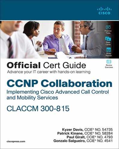
Understanding call legs and call flows is very important for the upcoming sections and chapters. A single call leg includes all the Layer 7 signaling and media for establishment of a given session between two devices. An end-to-end call has multiple call legs that establish separate sessions with different devices. Figure 8-1 shows all the call legs for a call that traverses the enterprise LAN and is sent to the service provider network. A diagram of these call legs, like the one in Figure 8-1, is referred to as a call flow. Basically, a call flow is a grouping of Layer 7 signaling and media information that pertains to the devices involved in a specific call. A call flow differs slightly from the Layer 1, 2, and 3 network topology diagrams used by network engineers. Network topology diagrams are usually more granular than application level diagrams such as call flows. Each hop of a call flow contains a call leg that traverses a network at Layer 1, 2, and 3, but these layers are usually omitted from a call flow diagram.
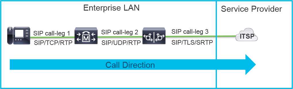
Figure 8-1 Call Flow Diagram Detailing the Application Hops in a Given Call
Keeping an up-to-date call flow diagram for application layer signaling and media along with an up-to-date network topology is very beneficial to any administrator’s troubleshooting, designing, and planning activities. Remember that the call flow does not end at the service provider. There are many more call legs and hops as the call traverses the network and other service provider networks, although they are usually omitted from an enterprise call flow as they are not usually known.
Tip
Call flow diagrams may include Layer 4 transport information, which is often useful for troubleshooting.
From the perspective of CUBE, there is always an inbound call leg and an outbound call leg for a session traversing the SBC. The inbound call leg consists of the ingress and egress SIP signaling involving a SIP user agent client (UAC). This UAC may be the ITSP, Cisco Unified CM, or a third-party SIP client. CUBE answers this signaling and takes the role of user agent server (UAS) for that call leg. CUBE then uses information from the ingress SIP messaging coupled with the configuration defined by the administrator to make a logical call routing decision. Upon deciding where to route the call, CUBE assumes the role of UAC and originates a new SIP session, with the UAS determined by the previous call routing logic. This second SIP session is the outbound call leg. Figure 8-2 illustrates inbound and outbound call legs with respect to the SIP signaling and call directions.
![]()

Figure 8-2 B2BUA Operation with Inbound and Outbound Call Legs
Note the following in Figure 8-2:
• The inbound call leg starts on the side of the device where the first session establishment message is received.
• The outbound call leg consists of the side of the call where the device extends the call to the next hop with a new session establishment message.
• Both inbound and outbound call legs consist of bidirectional (sent and received) signaling messages.
• This figure shows a high level SIP three-way handshake that consists of the INVITE, 200 OK, and ACK messages as CUBE performs back-to-back user agent (B2BUA) functions.
Because B2BUA operation is not clearly defined by any RFC, the actual interworking varies greatly by SBC vendor. By default, CUBE works to echo any SIP signaling received on one call leg to the peer call leg. For example, with CUBE, a SIP 183 Session in Progress message received on the outbound call leg would be transmitted on the peer inbound call leg. Figure 8-2 illustrates this for a basic call setup through CUBE. For granular control, CUBE has many configurations that allow you to change the way CUBE handles interworking during specific scenarios; you can even outright block specific messages from being passed through CUBE. (These features are covered in Chapter 9, “CUBE Interworking Features.”)
Tip
It is very important to remember that the terms inbound call leg and outbound call leg refer to the direction of the call from perspective of the device you are currently working with rather than the direction of the overarching call. Inbound calls to your LAN from a service provider and outbound calls from your LAN to a service provider will always have an inbound call leg and an outbound call leg from CUBE’s perspective.
Because it is an SBC, CUBE’s core functionality is to interact with VoIP call legs and interwork connections between multiple LANs for the purpose of routing calls. The two main VoIP protocols that CUBE uses are H.323 and SIP. CUBE can natively interwork four different permutations of the calls with only a few commands; any combination of SIP–SIP, SIP–H.323, H.323–SIP, and H.323–H.323 calls can be routed through CUBE. Note that when SIP–SIP interworking is being performed, CUBE is acting as a back-to-back user-agent (B2BUA). For other scenarios, such as H.323–H.323, SIP–H.323, and H.323–SIP, CUBE is acting as an IP-to-IP gateway (IPIPGW). These interworking scenarios are disabled by default, but Example 8-1 details four allow-connections commands that are used to enable these permutations. This example also details the mode border-element command, which is required to enable a CUBE license, and the show cube status command, which is used for gathering a quick verification of the CUBE version running on the IOS platform.
Example 8-1 Sample CUBE Configuration for Protocol Interworking
rtp-cube# show run | section voice serv
voice service voip
 mode border-element license capacity 100
 allow-connections h323 to h323
 allow-connections h323 to sip
 allow-connections sip to h323
 allow-connections sip to sip

rtp-cube# show cube status
CUBE-Version : 12.7.0
SW-Version : 16.12.1a, Platform ISR4321/K9
HA-Type : none
Licensed-Capacity : 100
Tip
CUBE versions are directly tied to IOS versions. Upgrading or downgrading IOS also upgrades or downgrades CUBE. When running multiple feature and services, you should always consult the applicable feature roadmaps and release notes to ensure that key features are not lost when performing downgrades.
IOS Dial Peers
A dial peer is an IOS command set that allows an administrator to accept and route calls through CUBE. In modern IOS deployments, dial peers come in two flavors: Plain Old Telephony Service (POTS) dial peers and voice over IP (VoIP) dial peers. POTS dial peers are used to interface with analog and digital connections, such as Foreign Exchange Station (FXS), Foreign Exchange Office (FXO), Ear and Mouth (E&M), E1 R2, T1/E Primary Rate Interface (PRI), and Basic Rate Interface (BRI). These legacy connections are used by IOS voice gateways to interoperate with private branch exchange (PBX) systems, PSTN service providers, and analog endpoints such as fax machines. Because the CCNP blueprint explicitly states that the CLACCM 300-815 exam covers CUBE dial peers, POTS dial peers are not discussed in this chapter. Instead, this chapter discusses VoIP dial peers and how they operate for SIP.
Dial peers can best be compared to the concept of static routing commands used for Layer 3 packet routing. Dial peers are created and match criteria statements are defined using wildcards and regular expressions (regex). Two logical operation descriptions of dial peers appear in debugging output: inbound dial peers for association with inbound call legs and outbound dial peers for association with and creation of outbound call legs. A dial peer contains a host of configurations that allow administrators and CUBE to exert control and perform interworking on the matching call legs of a session. A number of commands can be used to control various aspects of a call, such as DTMF relay, codecs/media operation, Layer 4 transport, VoIP protocol usage, encryption, calling/called translations, and SIP header interworking.
A three-level hierarchy for configuration preference defines which commands and their actions are applied to a given call leg on CUBE. The following is the command preference order, starting with the most explicit preference:
![]()
1. Dial peer configuration commands: These IOS commands are applied to inbound and outbound dial peers used by a session. These commands take precedence over all other configurations.
2. Voice class tenant configuration commands: A voice class tenant is a CLI command structure that facilitates grouping of system-level commands for specific tenants. Multitenancy is a feature in CUBE that enables administrators to host multiple organizations, customers, or other differentiated services on the same CUBE. Through the use of the voice class tenant command, an administrator can configure a host of settings for a specific tenant while also configuring different system-level settings for a different tenant. When these settings are applied to a dial peer, the dial peer inherits all of the command settings defined on the tenant. Dial peer commands still override voice class tenant settings when both exist.
3. Global configuration commands: Commands applied to sip-ua, voice service voip, or sip subsection of voice service voip are applied to all calls traversing CUBE. These commands can be overwritten by voice class tenant or dial peer–level configurations.
The following sections detail how to configure these dial peers to match on either an inbound call leg or an outbound call leg.
Inbound Dial Peer Matching
Every session that is established through CUBE uses an inbound dial peer. The dial peer selected is assigned to the inbound call leg, and the configuration defined by the administrator is leveraged by CUBE to exert control over the signaling and media negotiation for that call leg. Commands on the inbound dial peer also influence aspects of IOS call routing decisions and outbound dial peer selection, as discussed later in this chapter.
When IOS receives a new session and VoIP signaling message on a listening IP address and port, CUBE processes the following sequence of events for the inbound call leg:
Step 1. CUBE applies global number translations or inbound SIP profiles.
Step 2. CUBE filters dial peers based on virtual routing and forwarding (VRF) criteria.
Step 3. CUBE selects an inbound dial peer based on the defined matching commands.
Step 4. CUBE applies configurations such as more translations, SIP profiles, and binds to the VoIP signaling message.
Step 5. CUBE sends an acknowledgement message to stop retransmission of the VoIP signaling message from the sending device. For SIP, this is usually in the form of a 100 Trying message.
Table 8-2 show the IOS selection preference and the commands used to define the matching preference on dial peers. Defining any of these commands on a VoIP dial peer enables that dial peer for inbound selection. CUBE examines all dial peers that are configured with the commands found in the rightmost column of a given row of the table. CUBE examines different portions of the ingress VoIP signaling message and compares them to the wildcards and regex defined by match criteria commands. (Wildcards and regex are covered later in this chapter.) If a valid match is found, inbound dial peer hunting stops. Inbound dial peer hunting moves to the next row’s match criteria only when zero eligible matching dial peers have been found for the specific match criteria. For rows that have more than one command in the rightmost column, the commands have equal weight, and all dial peers with those match criteria commands are processed at the same time. This process is repeated for each row of the table until an applicable match for given match criteria has been found.
![]()
Table 8-2 Inbound SIP Dial Peer Selection Preference

Tiebreakers and Longest and Most Specific Matching Logic
![]()
The dial-peer preference command does not influence inbound dial peer selection when there are multiple dial peers with the same match criteria that could be selected, based on the ingress VoIP signaling message. CUBE uses the concept of the longest and most specific match to determine the priority. “Longest” and “most specific” refer to how many numeric digits (or alphanumeric characters for URIs) are matched on a regular expression run against a given input. In short, a dial peer with a match criteria command containing a more exact match will always be leveraged over a dial peer that is less exact. Example 8-2 shows two potential dial peers that can match the called number 1001. The first dial peer, 1000, has an exact match on the first digit (1), but the second dial peer (1001) has an exact match on three digits (100). Thus, dial peer 1001 is the longest, most specific match for the given called number and is therefore used as the inbound dial peer for this example. When two inbound dial peers of given match criteria have the same match length and are still tied, IOS selects the first of the tied dial peers according to the order of the running configuration. This is true for both URI and number matching criteria commands.
Example 8-2 Sample Configuration for Inbound Dial Peer Matching Based on Called Number
!
dial-peer voice 1000 voip
 incoming called-number 1...
!
dial-peer voice 1001 voip
 incoming called-number 100.
!
Because IOS only moves to the next row’s match criteria when zero applicable matching dial peers have been found, there is a possibility that a match criteria command with a better longest and most specific match may not be used if IOS finds an applicable match on a dial peer with a higher-preference match criteria command. For example, a dial peer with an exact match incoming calling or answer-address command may not ever be examined by IOS when a catch-all incoming called-number . command exists. IOS selects the dial peer with the incoming called-number command in this scenario because it satisfies matching conditions of being the longest and most specific match for that row’s match criteria (even if the match is a single digit). Likewise, if an applicable incoming uri command can match on a SIP header, the incoming calling and incoming called-number commands will never be examined.
Dial Peer Wildcards and Regex
For the dial peer match criteria commands that match on numeric strings, you can configure IOS wildcards and regex to define the range of numbers you would like a dial peer to service. Table 8-3 shows the different dial peer wildcard options, limited regex values, and usage examples and descriptions. You will see an example of regex and wildcard commands in the upcoming Example 8-4 for inbound dial peer matching using incoming called-number statements.
![]()
Table 8-3 Regex and Wildcard Commands Used by IOS Dial Peers

Dial Peer Filtering
As mentioned earlier in this chapter, dial peers are first filtered before the match criteria are examined. When the signaling is received on an interface with a VRF tag assigned, all dial peers are filtered to include only those associated to the VRF instance of the ingress interface. The VRF association is created by binding the dial peer to the interface with the VRF instance. The VRF instance–to–dial peer association is created when a dial peer is bound to an interface that has been assigned to a VRF instance with the vrf forwarding command. VRF instances are often employed alongside voice class tenant configurations discussed earlier in the chapter.
Figure 8-3 shows a SIP message received by CUBE, the filtering that occurs, and the dial peer match criteria evaluated from the different parts of the SIP message (refer to Table 8-2).

Figure 8-3 Sample Mapping of Dial Peer Match Criteria Commands and a SIP INVITE Message
Dial Peer 0, the Default Inbound Dial Peer
As mentioned at the beginning of this section, CUBE always associates an inbound call leg with an inbound dial peer. This is true even when no configured dial peer satisfies the IOS match criteria condition checks laid out in the previous paragraphs. When this scenario occurs, the default dial peer 0 is used as the inbound dial peer. This is a less-than-ideal situation in most cases because dial peer 0 is not configurable and contains a set of static capabilities that may affect session establishment in a negative way:
![]()
• Dial peer 0 has no DTMF relay mechanisms.
• Dial peer 0 advertises all voice codecs for VoIP calls.
• Dial peer 0 uses fax-rate voice.
• Voice activity detection (VAD) is enabled for dial peer 0.
• Dial peer 0 does not support RSVP.
• Dial peer 0 does not support IVR for basic telephone service (POTS) calls.
• Direct inward dialing (DID) is enabled for dial peer 0.
• Dial peer 0 does not support VRF instances.
Given these issues, it is better to configure an inbound dial peer than to match dial peer 0.
Although dial peer 0 is the default and not configurable, you can assign another VoIP dial peer on CUBE as the system default inbound dial peer. This dial peer can then be configured with various parameters and will be matched in place of dial peer 0. This gives you flexibility to change the parameters leveraged when the default dial peer is selected. Example 8-3 shows the commands for enabling a VoIP dial peer as the system default to enable capabilities not available with dial peer 0. At the end of the example, the show dial-peer voice command is used to verify that this dial peer has the system default attribute.
Example 8-3 Sample Configuration Showing the Creation of a Default Inbound Dial Peer
Router# show run | section 999
dial-peer voice 999 voip system
 dtmf-relay rtp-nte
 codec g711ulaw
 fax rate 9600
 no vad

Router# show dial-peer voice 999 | i default
        peer type = voice, system default peer = TRUE, information type = voice,
Matching Inbound Call Legs Using incoming called-number Commands
![]()
This chapter has already discussed the order of operations IOS uses for matching inbound calls to an inbound dial peer. This section examines how to use the incoming called-number command to perform a match on the numeric phone number and avoid matching dial peer 0.
Say that two phone calls are received at CUBE from a peer SIP user agent and require matching an inbound dial peer. CUBE finds these called numbers in the SIP INVITE Request-URI:
• INVITE sip:[email protected]:5060 SIP/2.0
• INVITE sip:[email protected]:5060 SIP/2.0
This example assumes that the enterprise PSTN access code is 9; that is, 9 is the code that users of end devices must dial to reach the public PSTN. Given the called number 14085267209, we can assume that dial peer 2 in Example 8-4 will be used as the inbound dial peer due to the regex match of a single dot (any character). Since the called number 14085267209 does not start with a 9, dial peer 22 will not be used. Further, we can observe that the called number 918005532447 matches dial peers 2 and 22 in various ways. Since these are all incoming called number statements, they are all evaluated to find the longest, most explicit match. The match on dial peer 2 for 918005532447 is a single digit: the leading 9. The match on dial peer 22 is four digits, so this is a longer, more explicit match (918xx5xxxxxx of 918005532447). Because dial peer 22 is the longest, most specific match, it will be used as the inbound dial peer for this call. Example 8-4 shows the use of the show dial-peer voice summary command, which indicates these dial peers are administratively up and operationally up, which means they are eligible for inbound dial peer matching based on their matching criteria commands. The same logic observed in this example can be replicated to the incoming calling or answer-address commands.
Example 8-4 A Sample Configuration Showing Inbound Dial Peers
rtp-cube# show run | section dial-peer
!
dial-peer voice 2 voip
 session protocol sipv2
 incoming called-number .
!
dial-peer voice 22 voip
 session protocol sipv2
 incoming called-number 91[2-9]..[2-9]......
!

rtp-cube# show dial-peer voice summary
dial-peer hunt 0
             AD                             PRE PASS SESS-SER-GRP  OUT
TAG    TYPE  MIN  OPER PREFIX  DEST-PATTERN FER THRU SESS-TARGET    STAT PORT KEEPALIVEVRF
2      voip  up   up                         0  syst                                   NA
22     voip  up   up                         0  syst                                   NA
Matching Inbound Call Legs Using URIs
URI-based dial peer matching for SIP makes use of voice class uri commands, which are configured with subcommands that use standard regex to match on different portions of a SIP header’s URI. URIs in SIP headers have a few distinct parts that can be leveraged for dial peer matching, and Table 8-4 details the order of operations used to evaluate a SIP URI. (For more information on SIP URI structuring, refer to Chapter 2, “VoIP Protocols: SIP and H.323.”)
![]()
Table 8-4 Voice Class URI Match Preference Order Used by CUBE

Tip
Match preferences 1 and 2 can be reversed with the command voice class uri sip preference user-id host, which instructs CUBE to check the user ID before checking the host portion of the URI.
Example 8-5 shows the syntax for the voice class uri command along with the optional subcommands. The name option is an administrator-defined name, and the regexMatch option is a regex string up to 32 characters long for user ID/host matches and 128 characters long for pattern matches.
Example 8-5 Voice Class URI Command Syntax
! SIP URI
voice class uri name sip
 host regexMatch
!
voice class uri name sip
 user-id regexMatch
!
voice class uri name sip
 phone regexMatch
!
voice class uri name sip
 pattern regexMatch
!
! Tel URI
voice class uri name tel
 phone regexMatch
!
voice class uri name tel
 pattern regexMatch
!
Tip
Up to 10 host commands can be configured on a single voice class uri command. Phone, pattern, and user-id only one definition per voice class uri command.
Using the information in Example 8-5, Example 8-6 details an inbound SIP message and a match that is configured to occur on the SIP Via header. This involves first defining a voice class uri to match the host IPv4 address. The voice class uri is then added to a dial peer using the incoming uri command. Any call that has a Via header containing IPv4 address 172.18.110.65 then uses dial peer 2 as the inbound dial peer.
Example 8-6 A Sample Depicting a Voice Class URI Match Using the Via SIP Header
# Inbound INVITE
INVITE sip:[email protected]:5060 SIP/2.0
Via: SIP/2.0/UDP 172.18.110.65:5060;branch=z9hG4bKBB1BE5
From: <sip:[email protected]>;tag= 4FD707ED-1319
To: <sip: [email protected]:5060>

! Voice Class URI Configuration
voice class uri viaHeader sip
 host ipv4:172.18.110.65
!
dial-peer voice 2 voip
 session protocol sipv2
 incoming uri via viaHeader
!
Example 8-7 shows how to define various voice class uri statements to further illustrate voice class uri usage. For example, voice class uri HOST sip can perform a match on many different types of host URIs, including regex matches, DNS fully qualified domain names (FQDNs), and IPv4 and IPv6 addresses. voice class uri USER sip and voice class uri UserRegex sip show how to match aspects of the user ID portion of a URI.
At the end of Example 8-7 are more regex samples that use the pattern command to perform more complex regex matches on any aspect of the URI. voice class uri ipRegex sip is a one-line statement that matches 172.18.110.101, 172.18.110.103, 172.18.110.104, or 10.10.10.10 via the pipe regex character (|), which indicates a ternary OR operation, and thus matches the first regex statement OR the second regex statement within the parentheses.
With a bit of practice, you can leverage voice class uri statements to match dial peers in ways that match statements such as incoming called-number, answer-address, and incoming calling do not allow. You can then apply these statements to a dial peer by using the syntax defined in the right column in Table 8-2. Example 8-7 ends with the assignment of multiple incoming uri commands to a dial peer for inbound dial peer examination for the Via, Request-URI, To, and From SIP header URIs.
Example 8-7 A Collection of Miscellaneous Voice Class URI Commands and Their Uses
! Creation
voice class uri HOST sip
 host (.*).webex.com
 host dns:ccnpcollab.lab
 host ipv4:172.18.110.42
 host ipv6:[2000::27E:95FF:FE8C:9991]
!
voice class uri USER sip
 user-id testUsername
!
voice class uri UserRegex sip
 user-id test(.*)
!
voice class uri patternRegex sip
 pattern 86753.*
!
voice class uri hostRegex sip
 pattern (.*).cisco.com
!
voice class uri portRegex sip
 pattern :5065
!
voice class uri ipRegex sip
 pattern (172.18.110.10[134]|10.10.10.10)
!
! Assignment
dial-peer voice 2222 voip
 session protocol sipv2
 incoming uri via HOST
 incoming uri request hostRegex
 incoming uri to patternRegex
 incoming uri from portRegex
!
Tip
All inbound matching commands can be defined on a dial peer at the same time. For example, the incoming called-number and incoming uri statements can both reside on the same inbound dial peer. The dial peer match criteria commands are still evaluated according to the preference order in Table 8-2.
Now that we have covered inbound dial peer matching techniques, the next section discusses how CUBE makes call routing decisions and selects outbound dial peers.
Outbound Dial Peer Matching
The previous sections of this chapter detail how to match an inbound call leg to an inbound dial peer. This section examines how to achieve CUBE’s main functionality and route calls to the next-hop call agent. Here we look at outbound dial peers. IOS has an order of operations that defines the method of selecting outbound dial peers. Table 8-5 details this order of operations.
IOS examines each row’s match criteria and dial peer match criteria commands for an applicable match to route a call to the next-hop call agent. If a match is found, outbound dial peer matching checks stop, and the call is routed using the configuration on that dial peer. If zero eligible dial peer matches are found for a row’s match criteria commands, the next row’s match criteria is examined. This process repeats until there are no more dial peers to check. Unlike with inbound dial peers, there is no default outbound dial peer. If no matches are found on any match criteria command, the call fails with a SIP 404 Not Found error and cause code 1 for an unallocated number.
![]()
Table 8-5 Outbound SIP Dial Peer Selection Preference

Outbound Dial Peer Hunting Logic and Tiebreakers
![]()
When attempting to route a call and perform an outbound dial peer selection, IOS uses the logic dictated by the dial-peer hunt command to determine which dial peer of a given match criteria should be used. The default configuration for dial-peer hunt is 0, which indicates “Longest match in phone number, explicit preference, random selection.” As this suggests, the concept of longest, most specific match applies to outbound dial peers just as it applies to inbound dial peers. When two dial peers with a given match criteria command can route a call, the one with the most explicitly defined digits takes precedence. If both dial peers have the same number of explicit digits, IOS looks at the administrator’s defined preference command. The default dial peer preference is 0, with that value, zero, also being the highest (most important) preference. If there is still a tie, IOS selects one of the two dial peers at random. This type of hunting can be changed by using the command syntax shown in Example 8-8. To view the current outbound dial peer hunting, you use the show dial-peer voice summary command and check the first line of the output for the current configuration. In Example 8-8, the show command output also indicates that the two dial peers configured for outbound call routing are administratively up and operationally up. For an outbound dial peer to be up/up, both an outbound matching command and next-hop session information must be configured. Omitting either of these items will remove the dial peer from outbound call routing selection. (The following sections provide more information about these two prerequisites and their required commands.)
Example 8-8 CLI Output Detailing Dial Peer Hunt Usage Definitions
rtp-cube(config)# dial-peer hunt ?
  <0-7>  Dial-peer hunting choices, listed in hunting order within each choice:
0 - Longest match in phone number, explicit preference, random selection.
  1 - Longest match in phone number, explicit preference, least recent use.
  2 - Explicit preference, longest match in phone number, random selection.
  3 - Explicit preference, longest match in phone number, least recent use.
  4 - Least recent use, longest match in phone number, explicit preference.
  5 - Least recent use, explicit preference, longest match in phone number.
  6 - Random selection.
  7 - Least recent use.

rtp-cube# show dial-peer voice summary
dial-peer hunt 0
             AD                             PRE PASS SESS-SER-GRP  OUT
TAG    TYPE  MIN  OPER PREFIX  DEST-PATTERN FER THRU SESS-TARGET    STAT PORT KEEPALIVE VRF
3      voip  up   up           1408.......        0  syst ipv4:172.18.110.91            NA
33     voip  up   up           9T                 0  syst ipv4:172.18.110.65            NA
Routing Calls with destination-pattern and session target
![]()
Most deployments route calls based on the called number. In this scenario, the most common outbound dial peer command is destination-pattern. This command utilizes dial peer wildcards and regex to perform a match on the called number. However, unless you instruct CUBE where to send the call when this dial peer is matched, the destination-pattern command alone does not offer much value. You must also configure a session target that defines the Layer 3 addressing information of the next-hop device CUBE will attempt to establish a session with and route the call toward.
Let’s say that CUBE receives two different phone calls, each with a different SIP INVITE message. The inbound dial peer matching has been completed, and you now need to select an eligible outbound dial peer to route the call. The following called numbers are found in the SIP INVITE’s Request-URI:
• INVITE sip:[email protected]:5060 SIP/2.0
• INVITE sip:[email protected]:5060 SIP/2.0
Example 8-9 shows two dial peers configured on CUBE. For the first number, 14085267209, dial peer 3 can be used to route the call based on the destination-pattern 1408....... command matching 1408xxxxxx of the called number 14085267209. IOS creates an outbound TCP SIP connection to the IPv4 address 172.18.110.91 as per the configured outbound session transport, session protocol, and session target commands. For the second number, 918005532447, dial peer 33 and 333 both match on the same number of digits (the leading 9). As a result, with the default dial peer hunting scheme, IOS looks at the preference assigned to the dial peer. Dial peer 333 has a preference of 1, and dial peer 33 has a preference of 2. This means dial peer 333 is used for the outbound connection. CUBE then establishes a UDP SIP session with 172.18.110.66 as per the two commands session protocol and session target. Because the session transport command is not configured, the dial peer assumes the default global outbound transport type, which would be configured in sip subsection of voice service voip using the same session transport command. If that has not been defined either, UDP will be used as the default value for outbound session transport.
Example 8-9 A Sample Configuration for Multiple Outbound Dial Peers
rtp-cube# show run | section ice 3
dial-peer voice 3 voip
 destination-pattern 1408.......$
 session protocol sipv2
 session target ipv4:172.18.110.91
 session transport tcp
!
dial-peer voice 33 voip
 preference 2
 destination-pattern 9..........$
 session protocol sipv2
 session target ipv4:172.18.110.65
 huntstop
!
dial-peer voice 333 voip
 preference 1
 destination-pattern 9..........$
 session protocol sipv2
 session target ipv4:172.18.110.66
!
Tip
Dial peers assume the default session protocol H.323 when the session protocol command is omitted from a VoIP dial peer.
![]()
IOS selects only one dial peer at a time for outbound call routing purposes. If a call setup failure occurs on the selected outbound dial peer, the next best outbound dial peer is used, and the outbound dial peer selection process proceeds normally. In this scenario, if the call setup signaling for dial peer 3 and 14085267209 failed, IOS would attempt to select a new dial peer. The remaining dial peers, 33 and 333, do not match the called number, and thus the call fails completely. With the second number, 918005532447, if dial peer 333 fails during the call setup signaling, dial peer 33 is attempted for outbound call routing purposes. If session establishment on this dial peer also fails, IOS typically continues hunting for eligible outbound dial peers. However, dial peer 33 in this example has the command huntstop, which instructs IOS to stop call routing and dial peer hunting if a call setup failure is observed on a session attempting to use that dial peer. As a result, dial peer 3 is never evaluated, and the call fails completely. The huntstop command should be applied to the last dial peer in a sequence of similar dial peers to avoid routing calls to undesired locations and potentially creating unwanted call loops. Note that if IOS establishes/connects a session using an outbound dial peer and the call fails later for any reason, dial peer hunting does not resume.
Table 8-6 describes the commands shown in Example 8-9.
Table 8-6 Outbound Dial Peer Commands

Tip
The commands show dial-peer voice numeric-tag or show run all | dial-peer voice numeric-tag can be used to view every setting of a dial peer, including the default settings not shown with a standard show run command. Replace numeric-tag with the numeric identifier assigned to the dial peer you want to view.
The session target command is a very important command for outbound call routing. After all, if IOS is not instructed where to send a call, the dial peer is not eligible for outbound call routing. Unfortunately, the context-sensitive help using the question mark (?) leaves much to be desired. Table 8-7 details all the different options for the session target command.
Table 8-7 Inputs for the session target target-address Command

Note
Session targets for SAF, loopback, and enumerations are beyond the scope of the CLACCM 300-815 exam but have been included in the table to provide a complete list. In addition, older IOS versions may accept arguments such as ras and settlement providers, which are no longer supported by CUBE.
The session target dns command has a few wildcard macro options that you can use in creative ways to influence DNS queries sourced from a device. Table 8-8 describes the wildcard values and provides examples.
Table 8-8 DNS Wildcards

Matching Outbound Dial Peers Using URIs
![]()
Just like their inbound counterparts, outbound dial peer matching commands can leverage SIP URIs. The destination uri command allows the outbound dial peer lookup and matches on the host portion of the Request-URI. Example 8-10 shows the commands required to enable call routing based on URI with CUBE. The call-route url command instructs CUBE to route calls based on the Request-URI. The voice class uri command is then leveraged to define the match statement for which IOS should check the Request-URI header. This is then applied to the outbound dial peer with destination uri CUCM. The session target command is then defined as session target sip-uri, which instructs IOS to derive the IP address of the next hop from the ingress Request-URI. Because we are using this for matching purposes, it is rtp-cucm.ccnpcollab.lab. The command requri-passing is needed because in normal operation, CUBE replaces the Request-URI and To headers with the IP address defined by the session target. With this command in place, CUBE passes the received URI in those two headers.
Example 8-10 also shows debugging using this configuration to route an inbound SIP INVITE message received with the Request-URI [email protected]. Inbound dial peer matching debugging has been excluded as the example focuses on the outbound dial peer operation. When performing outbound dial peer selection, CUBE selects dial peer 777, based on the destination uri statement configured using the voice class uri and host dns statements. When the outbound dial peer is selected, CUBE determines that the session target for the selected outbound dial peer is a SIP URI, and thus a DNS resolution is required to ascertain the IP address of the FQDN. Next, CUBE passes the Request-URI header from the inbound SIP message to the outbound SIP message, which is then put on the line and sent to the IP address gleaned from the DNS resolution.
Example 8-10 A Sample Configuration and Debugging Detailing How to Route Calls Based on the Request-URI Header
### Configuration
!
voice service voip
 sip
  call-route url
  requri-passing
!
voice class uri CUCM sip
 host dns:rtp-cucm.ccnpcollab.lab
!
dial-peer voice 777 voip
 session protocol sipv2
 destination uri CUCM
 session target sip-uri
!

### Debugging
005275: *Apr  9 18:11:42.529: //-1/xxxxxxxxxxxx/SIP/Msg/ccsipDisplayMsg:
Received:
INVITE sip:[email protected]:5060 SIP/2.0

005560: *Apr  9 18:11:42.537: //-1/824242DB804A/DPM/dpMatchPeersCore:
   Match Rule=DP_MATCH_DEST_URI; URI=sip:[email protected]:5060
005562: *Apr  9 18:11:42.537: //21/824242DB804A/CCAPI/ccCallSetupRequest:
   [..truncated..]
   Guid=824242DB-79C9-11EA-804A-B636EC901AA2, Outgoing Dial-peer=777

005622: *Apr  9 18:11:42.538: //16/665021018033/SIP/Info/verbose/16384/sipSPI_ipip_TargetTypeIsSipUri: Session Target is 'sip-uri'
005626: *Apr  9 18:11:42.539: //-1/xxxxxxxxxxxx/SIP/Info/verbose/5120/sipSPIGetOutboundHostAndDestHost: CCSIP: DNS resolution required..session target is 'sip-uri'

005978: *Apr  9 18:11:42.547: //16/665021018033/SIP/Info/verbose/16384/sipSPI_ipip_CopyUriFromIncToOutLeg: requri-passing: Req-URI is passed from Incoming to Outgoing Leg
005980: *Apr  9 18:11:42.547: //16/665021018033/SIP/Info/verbose/16384/sipSPI_ipip_GetReqUriFromTDContainer: Incoming Req-URI = sip:[email protected]:5060
005984: *Apr  9 18:11:42.547: //16/665021018033/SIP/Info/verbose/16384/sipSPI_ipip_CopyUriFromIncToOutLeg: Outgoing request-uri = sip:[email protected]:5060
005985: *Apr  9 18:11:42.547: //16/665021018033/SIP/Info/verbose/16384/sipSPI_ipip_CopyUriFromIncToOutLeg: requri-passing: To Hdr is passed from Incoming to Outgoing

006042: *Apr  9 18:11:42.549: //16/665021018033/SIP/Msg/ccsipDisplayMsg:
Sent:
INVITE sip:[email protected]:5060 SIP/2.0
Note
If a fully qualified domain name is in use for the Request-URI header, a successful DNS resolution needs to occur before it is possible to establish a session with the remote user agent.
Many other outbound dial peer matching commands are covered in the following sections.
Dial Peer Aggregation and Summarization Techniques
As an enterprise grows to include more and more devices that need to communicate with public networks, the number of dial peers that need to be configured for various scenarios also grows. Up to this point in the chapter, only a few dial peers have been used in the examples to illustrate specific topics. Imagine a scenario where there are many discontiguous direct inward dialing (DID) ranges that CUBE needs to handle for inbound calls, and there are many different dialing patterns required for outbound calls. There may be two or more Unified CM clusters with multiple call processing nodes for application redundancy. Similarly, there may be redundancy on the service provider network, with multiple IP addresses and trunks for PSTN redundancy. If you were to attempt a configuration that handles these variable and permutations by using the configurations examined up to this point, the number of dial peers required would be very high. The greater the number of dial peers, the greater the administrative overhead for maintaining and troubleshooting. Luckily, a few aggregation and summarization techniques can be used with CUBE to ease the administrative burden in scenarios like this.
E.164 Pattern Maps
![]()
One aggregation technique involves the use of an E.164 pattern map. With traditional dial peer configuration, you can configure only a single destination-pattern or incoming called-number command per dial peer. Even with regex and wildcards defined for maximum matches, this can mean a lot of dial peers. By using E.164 pattern maps, you can define a list of dial peer wildcard regex patterns as E.164 pattern entries and then apply an entire E.164 pattern map to a dial peer with either the incoming called e164-pattern-map or destination e164-pattern-map command. This effectively means that one dial peer can be configured to handle hundreds of incoming called number and destination pattern regex statements! Example 8-11 shows a sample configuration that can be used as a starting point for most CUBE deployments. In this example, e164-pattern-map 1 is used to match many of the different local, long-distance, and international dialing patterns used in the North American numbering plan (NANP). These all start with the enterprise PSTN outcall number 9. The last E.164 pattern matches 911 and 9911, depending on how an end user can dial the emergency number from an endpoint. This E.164 pattern map is then assigned to an inbound dial peer and an outbound dial peer for routing calls from the enterprise to the service provider network. In e164-pattern-map 2, there are multiple DID ranges defined; they refer to numbers owned by the enterprise. These numbers are then assigned to dial peers for routing inbound calls from the service provider PSTN to Unified CM on the enterprise LAN. The 4 dial peers in this configuration could easily be more than 16 dial peers with the traditional incoming called-number and destination-pattern commands.
Example 8-11 A Sample Configuration Using e164-pattern-map
! OUTBOUND Calls
voice class e164-pattern-map 1
 description E164 Pattern Map for PSTN Number Ranges
 e164 9[2-9]......$
 e164 91[2-9]..[2-9]......$
 e164 9011T
 e164 9?911$
!
dial-peer voice 1 voip
 description Incoming from CUCM to CUBE
 incoming called e164-pattern-map 1
 session protocol sipv2
!
dial-peer voice 11 voip
 description Outbound from CUBE to PSTN
 destination e164-pattern-map 1
 session protocol sipv2
 session target ipv4:172.18.110.65
!
! INBOUND CALLS
voice class e164-pattern-map 2
 description E164 Pattern Map for DID Number Ranges
 e164 1408.......$
 e164 1919574....$
 e164 1919392....$
 e164 +1T
!
dial-peer voice 2 voip
 description Incoming from PSTN to CUBE
 incoming called e164-pattern-map 2
 session protocol sipv2
!
dial-peer voice 22 voip
 description Outbound from CUBE to CUCM
 destination e164-pattern-map 2
 session protocol sipv2
 session target ipv4:172.18.110.48
!
Note that E.164 patterns maps can also be loaded from a .cfg file on the flash or a network location such as HTTP or FTP. When using a configuration file, up to 5000 E.164 entries can be present to allow for even greater aggregation and control. This file could be used manually or even levered for network automation purposes. Imagine a scenario where DIDs change regularly. Rather than change the E.164 pattern maps by hand, you could use a third-party DID management tool for DID management and tracking. This tool could output a .cfg file, in the required format, to a network location. You could then have CUBE access and load this file at a given time by using the voice class e164-pattern-map load and configuring a Kron policy with the kron command set, as shown in Example 8-12. You can use the command show voice class e164-pattern-map to view the contents of a static loaded E.164 pattern map. (For more information on IOS Kron policies, see https://www.cisco.com/c/en/us/td/docs/ios-xml/ios/cns/configuration/15-s/cns-15-s-book/cns-cmd-sched.html.)
Example 8-12 A Sample Showing Kron and E.164 Pattern Map Usage
!
voice class e164-pattern-map 11
 url http://http-host/config-files/pattern-map.cfg
!
dial-peer voice 11
 incoming called e164-pattern-map 11
 Session protocol sipv2
!
kron occurrence e164-pattern-load at 0:00 Sun recurring
 policy-list e164-pattern-load
!
kron policy-list e164-pattern-load
 cli voice class e164-pattern-map load 11
!
Session Server Groups
![]()
It is possible to aggregate multiple session target commands into one logical group by using the voice class server-group command. A server group can contain up to five IPv4 or IPv6 entries and is applied to an outbound dial peer. Using server groups along with E.164 pattern maps can greatly reduce the number of dial peers configured on a system when the next-hop devices leverage application redundancy through clustering. Example 8-13 shows a sample voice-class server-group command with IPv4 and IPv6 entries. This server group is set up for the round-robin hunting scheme. The default hunting scheme uses the preference defined by the administrator. The command show voice class server-group can be leveraged to view elements of a server group.
Example 8-13 A Sample Configuration Detailing Voice Class Server Group Usage
!
voice class server-group 22
 description CUCM Servers
 hunt-scheme round-robin
 ipv4 172.18.110.91 port 5060 preference 1
 ipv4 172.18.110.61 port 5060 preference 2
 ipv6 2000::245:1DFF:FED2:991 port 5060 preference 3
!
voice class e164-pattern-map 2
 description E164 Pattern Map for DID Number Ranges
 e164 1408.......$
 e164 1919574....$
 e164 1919392....$
 e164 +1T
!
dial-peer voice 2 voip
 description Incoming from PSTN to CUBE
 incoming called e164-pattern-map 2
 session protocol sipv2
!
dial-peer voice 22 voip
 description Outbound from CUBE to CUCM
 destination e164-pattern-map 2
 session protocol sipv2
session server-group 22
!
DNS SRV Load Balancing
As you might have noticed, there is not a DNS entry available in the voice class server-group configuration. In fact, DNS has a built-in load balancing mechanism. By leveraging DNS SRV load balancing, you can use a single session target dns entry to service any number of IP addresses and thus aggregate session targets and dial peers. RFC 2782 defines DNS SRV and indicates that a DNS SRV query has the following format:
_Service._Proto.Name TTL Class SRV Priority Weight Port Target
The fields in the SRV record are as follows:
• _Service: The name of the service being used.
• _Proto: The transport protocol used to communicate with the server.
• Name: The domain name for the request.
• TTL: The time to live, in seconds, which indicates how long the record will be cached by the DNS client.
• Class: SRV records belong to the INTERNET (IN) class with code type 22.
• Weight: The priority of the entry. The larger the weight, the higher the priority. The default is 0.
• Port and Target: The port and hostname of the device providing the service.
Upon receiving a DNS SRV query from a DNS client, a DNS server responds to the DNS SRV query with multiple A or AAAA records. Depending on the weight of these results, the DNS client can perform a second DNS lookup on the A or AAAA record to retrieve the IP address. CUBE can assume the role of a DNS client and attempt to perform different DNS SRV lookups, depending on the session protocol, session transport, session target dns, and voice-class sip url commands configured on the dial peer. Example 8-14 shows the different types of SRV lookups CUBE performs, along with the dial peer configurations that triggered the lookups.
Example 8-14 A Sample Configuration for DNS SRV Usage with Dial Peers
! _sip._udp. DNS SRV Query on port 5060
dial-peer voice 1 voip
 session protocol sipv2
 session transport udp
 session target dns:ccnpcollab.lab
!
! _sip._tcp. DNS SRV Query on port 5060
dial-peer voice 1 voip
 session protocol sipv2
 session transport tcp
 session target dns:ccnpcollab.lab
!
! _sip._tcp. DNS SRV Query on Port 5061
dial-peer voice 1 voip
 session protocol sipv2
 session transport tcp tls
 session target dns:ccnpcollab.lab
!
! _sips._tcp. DNS SRV Query on port 5061
dial-peer voice 1 voip
 session protocol sipv2
 session transport tcp tls
 session target dns:ccnpcollab.lab
 voice-class sip url sips
!
An administrator can force CUBE to skip the DNS SRV query by simply including a port at the end of the session target dns command. For example, session target dns:ccnpcollab.lab will perform a DNS SRV query while session target dns:ccnpcollab.lab:5060 will perform a regular DNS A record query.
CUBE can be configured to interface with an external DNS server or can be configured to perform DNS SRV lookups locally by also acting as a DNS server. In Example 8-15, the DNS name server is configured with the ip name-server command. If CUBE is the local DNS server, this command references CUBE’s IP address. Next, the IP domain lookup needs to be enabled. Then, depending on the dial peer configuration, one of the four groupings of SRV commands is configured by using ip host commands. The A record is defined at the end of a command. Finally, the A record–to–IP address mapping is defined in the last set of ip host commands.
Example 8-15 A Reference Configuration That Can Be Leveraged for Local DNS SRV Lookups
!
ip name-server 172.18.110.42
!
ip domain lookup
!
ip host _sip._udp.ccnpcollab.lab srv 1 50 5060 1.ccnpcollab.lab
ip host _sip._udp.ccnpcollab.lab srv 1 50 5060 2.ccnpcollab.lab
ip host _sip._udp.ccnpcollab.lab srv 1 50 5060 3.ccnpcollab.lab
!
ip host _sip._tcp.ccnpcollab.lab srv 1 50 5060 1.ccnpcollab.lab
ip host _sip._tcp.ccnpcollab.lab srv 1 50 5060 2.ccnpcollab.lab
ip host _sip._tcp.ccnpcollab.lab srv 1 50 5060 3.ccnpcollab.lab
!
ip host _sip._tcp.ccnpcollab.lab srv 1 50 5061 1.ccnpcollab.lab
ip host _sip._tcp.ccnpcollab.lab srv 1 50 5061 2.ccnpcollab.lab
ip host _sip._tcp.ccnpcollab.lab srv 1 50 5061 3.ccnpcollab.lab
!
ip host _sips._tcp.ccnpcollab.lab srv 1 50 5061 1.ccnpcollab.lab
ip host _sips._tcp.ccnpcollab.lab srv 1 50 5061 2.ccnpcollab.lab
ip host _sips._tcp.ccnpcollab.lab srv 1 50 5061 3.ccnpcollab.lab
!
ip host 1.ccnpcollab.lab 10.10.10.1
ip host 2.ccnpcollab.lab 10.10.10.2
ip host 3.ccnpcollab.lab 10.10.10.3
!
When debugging DNS issues on IOS, use the following show and debug commands to view currently cached IP addresses and debug the DNS SRV query process:
show host
debug ip domain
debug ip dns view
debug ccsip transport
Putting It Together
Together, E.164 pattern maps, session server groups, and DNS SRV queries can greatly reduce the total number of dial peers and the amount of administrative overhead involved in large collaboration deployments. The following section covers some advanced call routing scenarios. The summarization and aggregation techniques covered in this section can also be applied to the topics covered in the next section. Example 8-16 shows a sample configuration that leverages all of these summarization and aggregation techniques.
Example 8-16 A Reference Configuration That Leverages the Aggregation and Summarization Techniques Presented So Far
! OUTBOUND Calls from LAN to ITSP
voice class e164-pattern-map 1
 description E164 Pattern Map for PSTN Number Ranges
 e164 9[2-9]......$
 e164 91[2-9]..[2-9]......$
 e164 9011T
 e164 9?911$
!
dial-peer voice 1 voip
 description Incoming from CUCM to CUBE
 incoming called e164-pattern-map 1
 session protocol sipv2
!
dial-peer voice 11 voip
 description Outbound from CUBE to PSTN
 destination e164-pattern-map 1
 session protocol sipv2
 session target dns:myITSP.itspDomain.com
!
! INBOUND CALLS from ITSP to LAN
voice class e164-pattern-map 2
 description E164 Pattern Map for DID Number Ranges
 e164 1408.......$
 e164 1919574....$
 e164 1919392....$
 e164 +1T
!
voice class server-group 22
 description CUCM Servers
 hunt-scheme round-robin
 ipv4 172.18.110.91 port 5060 preference 1
 ipv4 172.18.110.61 port 5060 preference 2
!
dial-peer voice 2 voip
 description Incoming from PSTN to CUBE
 incoming called e164-pattern-map 2
 session protocol sipv2
!
dial-peer voice 22 voip
 description Outbound from CUBE to CUCM
 destination e164-pattern-map 2
 session protocol sipv2
 session server-group 22
!
Advanced Call Routing Techniques
So far in this chapter, we have looked at some common scenarios for matching inbound dial peers on incoming call legs, routing, and establishing an outbound call leg using an outbound dial peer. A key point to remember is that there is no standard configuration for routing calls through CUBE. The commands detailed in the previous sections give you granular control over how sessions are established and how inbound and outbound call legs are handled with CUBE. These commands can be leveraged in many different combinations and permutations to meet the call routing requirements of a business. The following sections show how to use the commands from the previous section to achieve advanced call routing requirements in various scenarios.
Dial Peer Groups (DPGs)
![]()
As you have already seen in this chapter, the inbound dial peer selected for an inbound call leg can play a role in the selection of outbound dial peers. One way to force a call to use a specific outbound dial peer if a specific inbound dial peer is selected is to use a dial peer group (DPG). A DPG creates a static association between an inbound dial peer and one or more outbound dial peers. This is the first option in Table 8-5 because no other outbound dial peer matching criteria are evaluated when a DPG exists on an inbound dial peer matched on the inbound call leg.
Example 8-17 shows a DPG configured with the command voice class dpg number. Dial peers are assigned with the dial peer subcommand, and a preference can optionally be applied. The default preference is 0 (which is also the highest preference). The DPG is then applied to the inbound dial peer by using the destination dpg command. In this scenario, the called number 14085267209 would match dial peer 4 as the inbound dial peer due to the exact match incoming called-number 14085267209 command. Because this dial peer is configured with a destination dpg command, IOS looks at the dial peer configured as the destination for the call. The dial peers configured on the DPG are ordered by preference, and IOS selects the highest-preference dial peer for the outbound dial peer. In this example, only dial peer 400 is configured, and it is selected as the outbound dial peer. An outbound call leg session is set up using TCP SIP with the IP address returned by the DNS query on the FQDN (sj-cucm.ccnpcollab.lab), as per the session transport, session protocol, and session target commands.
Note
In Example 8-17, destination-pattern has the value AAAAA, which does not match the called number 14085267209. IOS still selects this dial peer as the outbound dial peer. The reasoning is that the destination-pattern command is not evaluated when selecting an outbound dial peer defined by a DPG. The destination-pattern command is only required to place the outbound dial peer in an administratively up and operationally up state, as discussed earlier in this chapter. As a result, it is best to set destination-pattern for dial peers used in DPGs to a value such as AAAAA so that it is not easily selected erroneously for normal outbound call routing lookups on dial peers that do not have DPGs assigned. The command show voice class dpg can be used to view the contents of a given dial peer group.
Example 8-17 A Sample Dial Peer Group Configuration
!
voice class dpg 400
 dial-peer 400 preference 1
!
dial-peer voice 4 voip
 session protocol sipv2
destination dpg 400
 incoming called-number 14085267209
!
dial-peer voice 400 voip
destination-pattern AAAAA
 session protocol sipv2
 session target dns:sj-cucm.ccnpcollab.lab
 session transport tcp
!
Sourced-Based Call Routing with Dial Peer Groups
Source-based routing involves routing a call from a specific source to a static predefined destination, regardless of the calling/called number. The source match is performed by the voice class uri command assigned to an inbound dial peer. All calls with this source match the incoming uri statement, which is one of the first inbound match criteria checked. Then a DPG is assigned to the same inbound dial peer to force CUBE to use a specified outbound dial peer configured by the administrator. Example 8-18 shows voice class uri assigned to dial peer 5 to match all calls from a specific IP address in the SIP From header. When any call with a From header containing the IP address 172.18.110.65 is received, inbound dial peer 5 is selected, and the DPG is leveraged to select outbound dial peer 500 for outbound call routing. Note that dial peer 500 has destination-pattern set to AAAA, which forces the dial peer into an operationally up state. destination-pattern is not leveraged during this call as the DPG has already selected this dial peer as the outbound dial peer for the call.
Example 8-18 A Sample Configuration for Source-Based Routing
!
voice class uri 5 sip
 host ipv4:172.18.110.65
!
voice class dpg 500
 dial-peer 500
!
dial-peer voice 5 voip
 session protocol sipv2
 destination dpg 500
 incoming uri from 5
!
dial-peer voice 500 voip
 session protocol sipv2
 session target ipv4:172.18.110.91
 destination-pattern AAAA
!
Dial Peer Provision Policy Routing
![]()
A dial peer provision policy (DPP) allows you to use information from the inbound SIP header URIs as values for looking up an outbound dial peer. A DPP is created and then assigned to an inbound dial peer. When that inbound dial peer is leveraged for an inbound call leg, the policy is invoked, and outbound dial peers are evaluated according to the defined policy. The policy may define a single match criteria or two match criteria attributes that need to be evaluated on the outbound dial peers. When two match criteria attributes are configured on the same policy preference, both attributes are evaluated for matches at the same time. If either match statement fails to match the call properly, the outbound dial peer is not selected.
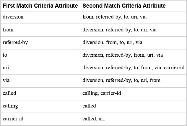
You can define two policies per DPP with the preference command. This preference also determines the order in which each policy will be evaluated. Policy preference 2 will be evaluated only when policy preference 1 returns zero applicable dial peer matches. Only one of the secondary attributes can be selected. The secondary attributes are filtered based on the primary attribute entered. Table 8-9 defines the permutations of primary and secondary policy attributes for the policy preference command.
Table 8-9 The Permutations of Match Criteria Attributes for a Dial Peer Provision Policy
The last DPP requirement is to configure the outbound dial peers to match by using the match attributes selected in the policy. Using the information from Table 8-9, you can now examine Table 8-10, which maps the attributes to their respective outbound dial peer match criteria commands.
Table 8-10 The Mapping of Dial Peer Match Criteria Commands to the Dial Peer Policy Syntax

Example 8-19 uses the information from Table 8-9 and Table 8-10 to show two specific scenarios using dial peer groups. Both of these scenarios use a common ingress SIP INVITE message, and the Request-URI, From, and To headers are displayed. Two voice-class uri commands are used: one for the From Header user ID and the second for the To Header user ID. A DPP has been created, with two preference options. The first preference instructs CUBE to search for an outbound dial peer that matches both the FROM and TO headers. Dial peer 12345 is outfitted with both destination uri-from FROM and destination uri-to TO, which point to the voice class uri commands defined earlier. The second policy is invoked only if the first policy returns zero matches. This second policy instructs IOS to look for whether the called number and dial peer 11111 has been configured with an exact match destination-pattern 14085267209 command.
Example 8-19 An Example of DPP Use on a Sample SIP INVITE Message
### Received INVITE
INVITE sip:14085267209@172.18.110.58:5060 SIP/2.0
From: <sip:18005532447@172.18.110.65>;tag=1
To: <sip: 14085267209@172.18.110.58:5060>
### Configurations
!
voice class uri FROM sip
 user-id 18005532447
!
voice class uri TO sip
 user-id 14085267209
!
voice class dial-peer provision-policy 1
 description match From AND To header. If false, try called number
 preference 1 from to
 preference 2 called
!
dial-peer voice 1234 voip
 session protocol sipv2
 destination provision-policy 1
 incoming called-number .
!
dial-peer voice 12345 voip
 destination uri-from FROM
 destination uri-to TO
 session protocol sipv2
 session target ipv4:172.18.110.48
!
dial-peer voice 11111 voip
 destination-pattern 14085267209
 session protocol sipv2
 session target ipv4:172.18.110.48
!
Dial Peer Groups Versus Dial Peer Provision Policies
DPGs and DPPs both enable you to influence outbound dial peer matching and call routing based on the incoming call leg and incoming dial peer. The main difference between the two options is that DPGs are far more static and less customizable. That is, the mapping of inbound dial peer to outbound dial peer for matching does not leave much room for intricate call routing. With a DPP, on the other hand, there is far more room for customization. You can leverage DPP to force CUBE to perform an outbound dial peer lookup using specific match criteria commands. These commands can use traditional dial peer wildcard and regex statements. The customization possible with a DPP can be useful for solving complex call routing requirements.
Intercluster Lookup Service (ILS) Call Routing on CUBE
As discussed in Chapter 4, “Unified CM Call Routing and Digit Manipulation,” SIP trunks can be configured to send the x-cisco-dest-route-string SIP header for outbound SIP INVITE messages when the Unified CM SIP profile setting Send ILS Learned Destination Route String is enabled. This header is very beneficial to CUBE as it may be placed in between two Unified CM clusters for ILS call routing. CUBE has a set of configurations you can leverage to assist with call routing in this type of deployment. Example 8-20 shows the configuration required to get a single direction working for ILS with CUBE between two Unified CM clusters.
Example 8-20 ILS Route String CUBE Configuration
!
voice class uri CISCO sip
 pattern cisco.com
!
voice class route-string 1
 pattern svs-alpha-c1.cisco.com
!
voice class sip-hdr-passthrulist 1
 passthru-hdr x-cisco-dest-route-string
!
dial-peer voice 1 voip
 description INBOUND dial-peer
 session protocol sipv2
 incoming uri request CISCO
 voice-class sip call-route url
 voice-class sip requri-passing
 voice-class sip pass-thru headers 1
!
dial-peer voice 2 voip
 description OUTBOUND dial-peer
 session protocol sipv2
 session target ipv4:10.122.249.70
 destination route-string 1
 voice-class sip call-route dest-route-string
!
The first thing you should notice about Example 8-20 is that it includes many of the commands previously discussed in this chapter. ILS can send alphanumeric SIP URIs, so CUBE needs to leverage these command sets to properly handle alphanumeric URIs. At the beginning of the example, you can see voice class uri configured for the pattern cisco.com, which will be used later to match the inbound dial peer, based on the domain portion of the SIP request. Next, the command voice class route-string defines a numeric tag and regex pattern for matching the x-cisco-dest-route-string SIP header. This will later be applied to the outbound dial peer. Next, the voice class sip-hdr-passthrulist command is configured with passthru-hdr for the x-cisco-dest-route-string SIP header that Unified CM will be supplying. (This is a defined header to pass through CUBE from the inbound call leg to the outbound call leg.) This command is discussed in more detail later in this chapter, but for now, just note that it is required here to ensure that the remote Unified CM server receives the destination route string information sent by the originating Unified CM server.
The next configuration is the inbound dial peer (dial peer voice 1 voip), which matches inbound SIP requests based on the CISCO voice class URI. The voice-class uri command should be well known by this point in the chapter; the syntax to apply to dial peer 1 is incoming uri request CISCO. Next, there are a few new variants of the voice-class sip command we looked at earlier in the chapter. Both voice-class sip call-route url and voice-class sip requri-passing operate the same as their goal voice service voip configuration counterparts commands described earlier in the this chapter:
• The voice-class sip call-route url command, when applied globally or on a dial peer, instructs CUBE to look at the entire SIP Request-URI rather than at the E.164 numeric-only user portion of the Request-URI header. Without this command configured, you would see a 484 Address Incomplete error along with cause code 28.
• The voice-class sip requri-passing command instructs CUBE to pass the Request-URI from the inbound call leg to the outbound call leg without modification. Remember that without this command, CUBE replaces the domain portion of the Request-URI with the session target configured on the outbound dial peer.
Finally, the inbound dial peer is configured to pass through the SIP headers from the aforementioned sip-hdr-passthrulist via the voice-class sip pass-thru headers command.
The outbound dial peer, created with dial-peer voice 2 voip, is configured as you would expect except for two new commands that are exclusive to the ILS feature:
• The destination route-string command references the voice class route-string and pattern configured earlier. During call routing operations, CUBE compares the received value in the x-cisco-dest-route-string header to any available destination route-string/voice class route-string patterns to determine if an outbound dial peer can be matched successfully.
• The voice-class sip call-route dest-route-string command enables CUBE for route string based call routing. This can be configured globally via the voice service voip and sip subsection, but for the sake of brevity, it has been configured only on the outbound dial peer, which is also configured with the destination route-string command.
With the configuration from Example 8-20 in place on CUBE, you can now route ILS calls for a remote Unified CM server through CUBE. (Refer to Chapter 4 for ILS configuration on Unified CM.) The debugging sample in Example 8-21 shows Unified CM sending a call to CUBE for [email protected] by using debug voip dialpeer along with debug voip ccapi inout and debug ccsip messages. You can see that the following steps occur:
Step 1. A SIP INVITE message is received for [email protected] with the X-cisco-dest-route-string value svs-alpha-c1.cisco.com.
Step 2. An inbound dial peer match for dial peer 2 is configured to match based on the cisco.com domain portion of the received Request-URI. This dial peer match also applies the commands for URI call routing, Request-URI passing, and header passthrough that are required for this type of call.
Step 3. The dial peer debugging shows CUBE checking the received route string against available dial peers and ultimately arriving at a match on dial peer 2 due to the two route string configurations applied to that dial peer.
Step 4. CUBE sends a SIP INVITE message to the session target configured on the dial peer. Notice that, due to the configuration on the inbound dial peer, the outbound SIP INVITE message contains the original Request-URI [email protected] rather than [email protected], along with the full x-cisco-dest-route-string, which has been successfully passed from the inbound call leg to the outbound call leg.
Example 8-21 ILS Route String Debugging Sample on CUBE
Received:
INVITE sip:[email protected] SIP/2.0
Via: SIP/2.0/TCP 10.122.249.59:5060;branch=z9hG4bK4416af0eda
From: <sip:[email protected]>;tag=438~393fe797-c548-472f-baf3-3bcafad7a475-18924723
To: <sip:[email protected]>
Call-ID: [email protected]
X-cisco-dest-route-string: <sip:svs-alpha-c1.cisco.com>
Aug  2 00:35:12.198: //-1/054FE5800000/CCAPI/cc_api_call_setup_ind_common:
   [..truncated..]
   Incoming Dial-peer=1, Progress Indication=NULL(0), Calling IE Present=TRUE,

Aug  2 00:35:12.200: //-1/054FE5800000/DPM/dpMatchPeersCore:
   Match Rule=DP_MATCH_DEST_ROUTE_STR; Destination Route-string=svs-alpha-c1.cisco.com

Aug  2 00:35:12.201: //-1/054FE5800000/DPM/dpMatchPeersMoreArg:
   Result=SUCCESS(0)
   List of Matched Outgoing Dial-peer(s):
     1: Dial-peer Tag=2

Aug  2 00:35:12.201: //49/054FE5800000/CCAPI/ccCallSetupRequest:
   [..truncated..]
   Guid=054FE580-0001-0000-0000-00293BF97A0A, Outgoing Dial-peer=2

*Aug  2 00:35:12.206: //50/054FE5800000/SIP/Msg/ccsipDisplayMsg:
Sent:
INVITE sip:[email protected] SIP/2.0
Via: SIP/2.0/UDP 172.18.110.58:5060;branch=z9hG4bK883D
From: <sip:[email protected]>;tag=9A9706-1298
To: <sip:[email protected]>
Call-ID: [email protected]
X-cisco-dest-route-string: <sip:svs-alpha-c1.cisco.com>
Next-Hop Availability Through SIP OPTIONS
CUBE can be configured to monitor the reachability of a next-hop session target on a dial peer by using out-of-dialog (OOD) SIP OPTIONS messages at defined intervals. The voice-class sip options-keepalive command applied on a dial peer sends a SIP OPTIONS message every 60 seconds when the dial peer is up. If there is no response, CUBE retries five more times before marking the dial peer as busyout. At this point, CUBE sends a SIP OPTIONS message to the session target every 30 seconds, with 5 retries. If the device responds, the dial peer is placed back into an active state. When a dial peer is busyout, it is ineligible for outbound call routing selection.
Dial peers are placed into busyout when one of the following occur:
![]()
• There are zero responses to an OOD SIP OPTIONS message and all retries are exhausted
• A 503 Service Unavailable Response is received
• A 505 SIP Version Not Supported Response is received
All other error codes including 4xx level error codes are considered a valid response and keep the dial peer active.
Note that a normal voice-class sip options-keepalive command does not track elements in a server group. Thus you should configure a voice-class sip options-keepalive profile to ensure that the status of every server group entry is checked. Example 8-22 shows a sample server group and keepalive profile configuration. A dial peer displays as active in show call active voice summary even when elements of the server group are down. To view the element status, you can issue show voice class sip-options-keepalive for the keepalive profile defined on the dial peer.
Example 8-22 A Sample OPTIONS Keepalive Profile Used with a Server Group
rtp-cube# show run | section server-group 33|voice 33 voip|options-keepalive
!
voice class sip-options-keepalive 33
 down-interval 30
 up-interval 60
 retry 5
!
voice class server-group 33
 ipv4 172.18.110.48
 ipv4 172.18.110.65
!
dial-peer voice 33 voip
 destination-pattern 1234
 session protocol sipv2
 session server-group 33
 voice-class sip options-keepalive profile 33
!

rtp-cube# show dial-peer voice summary
dial-peer hunt 0
             AD                            PRE PASS SESS-SER-GRP OUT
TAG    TYPE  MIN  OPER DEST-PATTERN FER THRU SESS-TARGET  STAT   PORT KEEPALIVE
33     voip  up   up   1234          0  syst SESS-SVR-GRP:33          active

rtp-cube# show voice class sip-options-keepalive 33
Voice class sip-options-keepalive: 33            AdminStat: Up
 Description:
 Transport: system               Sip Profiles: 0
 Interval(seconds) Up: 60                Down: 30
 Retry: 5

  Peer Tag      Server Group    OOD SessID      OOD Stat        IfIndex
  --------      ------------    ----------      --------        -------
  33            33                              Active          9

  Server Group: 33               OOD Stat: Active
   OOD SessID   OOD Stat
   ----------   --------
   3            Busy
   4            Active
 OOD SessID: 3                   OOD Stat: Busy
  Target: ipv4:172.18.110.48
  Transport: system              Sip Profiles: 0

 OOD SessID: 4                   OOD Stat: Active
  Target: ipv4:172.18.110.65
  Transport: system              Sip Profiles: 0
Tip
The command voice-class sip options-ping is used for in-dialog SIP OPTOINS messages (that is, SIP OPTIONS messages sent during an active session). This differs from voice-class sip options-keepalive, which sends an out-of-dialog (OOD) SIP OPTIONS keepalive message for checking next-hop reachability and service.
Verify and Troubleshoot IOS Call Routing
![]()
When deploying or operating CUBE, you might at some point need to investigate a call failure. You should work to determine the fault of the failure and employ corrective actions. Unlike Unified CM, CUBE does not have the same level of persistence storage that can be found in a fully-fledged server with dedicated hard drive disk space. CUBE uses the local IOS logging buffer to store debugging information, when enabled. Debugging is not usually left running in order to avoid inadvertently oversubscribing CPU and memory services. The downside is that you cannot perform an analysis on a call failure if debugging was not enabled. CUBE call failure troubleshooting is almost always done by reproducing the failure after IOS debugging is enabled and then gathering the data before it is overwritten in the logging buffer.
If you decided to keep debugging enabled and increased the logging buffer to a very high limit, there would still be a very small window of time before the debugging information would overwrite itself. Depending on how long it takes for a failure to occur and be reported by a customer, the logs might be long gone. This time window decreases exponentially as the number of calls per second handled by CUBE—and therefore the number of logs written to the buffer—increases. IOS syslogs can be leveraged to send IOS logs and debugging information to a dedicated syslog server, but you must be careful not to oversubscribe CPU and memory processes, thus causing more harm. With devices that handle thousands of calls, this might not be an option.
With SIP CUBE, the following debug commands can often be used to determine faults with call routing:
debug voip dialpeer
debug voice translation
debug ccsip messages
debug ccsip error
debug ccsip info
debug ccsip transport
debug voip ccapi inout
For more intrinsic issues, the commands debug ccsip all or debug ccsip verbose can be enabled, but you should never enable everything with these commands without first verifying that CPU usage is low enough that you will not impact production traffic.
Tip
Before enabling any debugging in CUBE, you should use show processes cpu sort and show processes cpu history to verify that CPU usage is not already above 50%. Enabling debugging may cause unwanted call failures due to CPU spikes.
The configuration in Example 8-23 can be leveraged to mitigate CPU spikes and ensure valid data collection when enabling debugging. These commands enable timestamps in the debugging down to the millisecond, with explicit sequence numbering to verify whether any logging data has been dropped. The buffer in this case is set to 10 million bytes, and logging to the console and monitor are disabled. These settings help mitigate CPU spikes that occur when trying to print debugging information to multiple terminals in real time. The queue limit and rate limit have been set to high limits to avoid dropping messages when very busy debugging is occurring. Finally, IEC syslogs have been enabled to provide some extra error logging when IOS is responsible for a call failure.
Example 8-23 A Reference Configuration That Can Be Used to Define Logging Parameters on IOS Gateways
service timestamps debug datetime msec localtime show-timezone year
service timestamps log datetime msec localtime show-timezone year
service sequence-numbers
logging buffered 10000000
no logging console
no logging monitor
logging queue-limit 10000
logging rate-limit 10000
voice iec syslog
When troubleshooting or verifying a dial plan, be sure to use the information in Tables 8-2 and 8-4 from the beginning of the chapter. It is a good practice to re-verify the dial peer being matched by a session in debugging even when you are confident in the configuration. Many issues are due to matching an undesired incorrect dial peer due to a misconfiguration. If a call is active, you can use the command show call active voice brief | include pid, as shown in Example 8-24, to filter the output to the lines that contain the dial peer matched on the incoming call leg (Answer) and outgoing call leg (Originate). If the call completed recently, the history variant of the same command can be leveraged: show call history voice br | i pid. The dial-control-mib retain-timer and dial-control-mib max-size commands can be leveraged to increase the show call history table. If there are many calls on the device, you should examine the caller ID information next to Answer and Originate to track your test call.
Example 8-24 show Command Output Detailing the Inbound and Outbound Dial Peer Match
Router# show call active voice brief | include pid
<ID>: <CallID> <start>ms.<index> (<start>) +<connect> pid:<peer_id> <dir> <addr> <state>
362B : 109 2251638910ms.1 (*20:01:46.396 EDT Tue Sep 17 2019) +2510 pid:1 Answer 7777 active
362B : 110 2251638930ms.1 (*20:01:46.416 EDT Tue Sep 17 2019) +2470 pid:11 Originate 1234 active
Basic CUBE Call Routing Debug Analysis
In this section, we examine a very basic inbound and outbound call through CUBE by using debugging. Example 8-25 shows the information using the commands mentioned so far in this section. This example shows a basic inbound dial peer with an incoming called number statement and an outbound dial peer with the destination pattern matching on the called number 14085267209. In the debugging output, you can see a received SIP message with the called URI [email protected]. CUBE attempts to match this call to any VRF instances for filtering dial peers, but none are found. Next, there is an attempt to match the call based on the called number, and you can see an incoming dial peer match of 1. With the inbound dial peer match done, CUBE must now route this call somewhere. A dial peer lookup is performed, and dial peers 2 and 3 are found. CUBE evaluates both dial peers to determine the longest, most specific match and finds that dial peer 2 has a more explicit match and thus is used. If the call fails on dial peer 2, dial peer 3 can be used as a backup.
The dial peer’s session target is a DNS entry, so CUBE must perform a DNS SRV query, which returns an A record, which is then queried to return the IP address 172.18.110.61. The dial peer has TCP as the session transport, so a TCP socket is established, and then the SIP INVITE message is built and sent to Unified CM, using the information of dial peer 2. Figure 8-4 illustrates debug outputs from a sample call using this process.
Example 8-25 A Basic Call Example and Debugging Walkthrough
! Config
dial-peer voice 1 voip
 session protocol sipv2
 incoming called-number .
 codec g711ulaw
!
dial-peer voice 2 voip
 preference 1
 destination-pattern 1408526....$
 session protocol sipv2
 session target dns:sj-cucm.ccnpcollab.lab
 session transport tcp
 codec g711ulaw
!
dial-peer voice 3 voip
 huntstop
 preference 2
 destination-pattern 1408.......$
 session protocol sipv2
 session target dns:rtp-cucm.ccnpcollab.lab
 session transport udp
 codec g711ulaw
!
! Debugs, Received INVITE
010303: Oct 14 14:54:40.960 EDT: //-1/xxxxxxxxxxxx/SIP/Msg/ccsipDisplayMsg:
Received:
INVITE sip:[email protected]:5060 SIP/2.0
Call-ID: [email protected]
! Debugs, VRF Checking
010314: Oct 14 14:54:40.961 EDT: //-1/000000000000/SIP/Info/info/8192/resolve_sig_ip_address_to_bind: VRF id = 0
010315: Oct 14 14:54:40.962 EDT: //-1/xxxxxxxxxxxx/SIP/Info/info/8192/resolve_sig_ip_address_to_bind: ip_best_local_address 172.18.110.62 for SIP
! Debugs, Inbound dial-peer searching
010370: Oct 14 14:54:40.968 EDT: //-1/E9A61FCE80DD/SIP/Info/verbose/67584/sipSPIGetShrlPeer: Try match incoming dialpeer for Calling number: : 18005532447
010388: Oct 14 14:54:40.969 EDT: //-1/E9A61FCE80DD/DPM/dpAssociateIncomingPeerCore:
   Calling Number=18005532447, Called Number=14085267209, Voice-Interface=0x0,
   Timeout=TRUE, Peer Encap Type=ENCAP_VOIP, Peer Search Type=PEER_TYPE_VOICE,
   Peer Info Type=DIALPEER_INFO_SPEECH
010409: Oct 14 14:54:40.970 EDT: //-1/E9A61FCE80DD/DPM/dpAssociateIncomingPeerCore:
   Match Rule=DP_MATCH_INCOMING_DNIS; Called Number=14085267209
010414: Oct 14 14:54:40.971 EDT: //-1/E9A61FCE80DD/DPM/dpAssociateIncomingPeerCore:
   Result=Success(0) after DP_MATCH_INCOMING_DNIS; Incoming Dial-peer=1
010578: Oct 14 14:54:40.984 EDT: //-1/E9A61FCE80DD/CCAPI/cc_api_call_setup_ind_common:
   Interface=0x7FDF3EC2BF48, Call Info(
   Calling Number=18005532447,(Calling Name=)(TON=Unknown, NPI=Unknown, Screening=Not Screened, Presentation=Allowed),
   Called Number=14085267209(TON=Unknown, NPI=Unknown),
   Calling Translated=FALSE, Subscriber Type Str=Unknown, FinalDestinationFlag=TRUE,
   Incoming Dial-peer=1, Progress Indication=NULL(0), Calling IE Present=TRUE,
   Source Trkgrp Route Label=, Target Trkgrp Route Label=, CLID Transparent=FALSE), Call Id=71
! Debugs, Outbound dial-per selection
010629: Oct 14 14:54:40.989 EDT: //-1/E9A61FCE80DD/DPM/dpMatchPeersMoreArg:
   Result=SUCCESS(0)
   List of Matched Outgoing Dial-peer(s):
     1: Dial-peer Tag=2
     2: Dial-peer Tag=3
010633: Oct 14 14:54:40.990 EDT: //-1/E9A61FCE80DD/DPM/MatchNextPeer:
Result=Success(0); Outgoing Dial-peer=2 Is Matched (8 digits)
010634: Oct 14 14:54:40.990 EDT: //-1/E9A61FCE80DD/DPM/MatchNextPeer:
Result=Success(0); Outgoing Dial-peer=3 Is Matched (5 digits)
010716: Oct 14 14:54:40.995 EDT: //71/E9A61FCE80DD/CCAPI/ccCallSetupRequest:
   Calling Number=18005532447(TON=Unknown, NPI=Unknown, Screening=Not Screened, Presentation=Allowed),
   Called Number=1000(TON=Unknown, NPI=Unknown),
   Redirect Number=, Display Info=
   Account Number=18005532447, Final Destination Flag=TRUE,
   Guid=E9A61FCE-EDEA-11E9-80DD-E8A5F2283ACD, Outgoing Dial-peer=2
! DNS SRV and A Record Query
011005: Oct 14 14:54:41.018 EDT: //-1/xxxxxxxxxxxx/SIP/Info/notify/8192/sip_dns_type_srv_query: TYPE SRV query for _sip._tcp.sj-cucm.ccnpcollab.lab and type:1
011006: Oct 14 14:54:47.024 EDT: //-1/xxxxxxxxxxxx/SIP/Info/info/8192/sip_dns_type_a_aaaa_query: DNS query for sj-cucm.ccnpcollab.lab and type:1
011009: Oct 14 14:54:47.026 EDT: //-1/xxxxxxxxxxxx/SIP/Info/info/8192/sip_dns_type_a_aaaa_query: IP Address of sj-cucm.ccnpcollab.lab is:
011010: Oct 14 14:54:47.026 EDT: //-1/xxxxxxxxxxxx/SIP/Info/info/8192/sip_dns_type_a_aaaa_query: 172.18.110.61
! Sent INVITE
011129: Oct 14 14:54:47.037 EDT: //72/E9A61FCE80DD/SIP/Msg/ccsipDisplayMsg:
Sent:
INVITE sip:[email protected]:5060 SIP/2.0
Call-ID: [email protected]

Figure 8-4 A Visualization of the Call and Debugging Information Analyzed in This Section
Example 8-26 demonstrates show commands you can use to view various aspects of active SIP sessions on CUBE. For example, you can use show sip-ua calls called-number or show sip-ua calls calling-number to gather lots of useful SIP signaling and RTP media information during an active call. The command show call active voice brief provides more information about a call, such as TX/RX counters for sent/received RTP packets along with other media and signaling information. You can use the compact form of the command (show call active voice compact) to get a quick at-a-glance view of an active call’s codec and remote media IP address. Finally, you can get complete media information for a call by using show voip rtp connections.
Note
IOS XE gateways require the command media bulk-stats to be configured via voice service voip in order to leverage TX/RX statistics.
Example 8-26 show Command Output for the Debugging Information from Example 8-25, Showing Similar Information
sj-cube# show call active voice brief
12C6 : 71 3459414160ms.1 (14:54:40.987 EDT Mon Oct 14 2019) +8780 pid:1 Answer 18005532447 active
 dur 00:00:23 tx:1140/228000 rx:1100/228000 dscp:0 media:0 audio tos:0xB8 video tos:0x0
 IP 172.18.110.65:6000 SRTP: off rtt:0ms pl:0/0ms lost:0/0/0 delay:0/0/0ms g711ulaw TextRelay: off Transcoded: No ICE: Off
 media inactive detected:n media contrl rcvd:n/a timestamp:n/a
 long duration call detected:n long duration call duration:n/a timestamp:n/a
 LostPacketRate:0.00 OutOfOrderRate:0.00
 LocalUUID:867251d0ebfc5155adc48564c2cff41b
 RemoteUUID:54e59c8c00105000a000c4b36aba1b5a
 VRF: NA

12C6 : 72 3459420210ms.1 (14:54:47.037 EDT Mon Oct 14 2019) +2690 pid:2 Originate 14085267209 active
 dur 00:00:23 tx:1100/228000 rx:1140/228000 dscp:0 media:0 audio tos:0xB8 video tos:0x0
 IP 14.50.214.108:28968 SRTP: off rtt:0ms pl:0/0ms lost:0/0/0 delay:0/0/0ms g711ulaw TextRelay: off Transcoded: No ICE: Off
 media inactive detected:n media contrl rcvd:n/a timestamp:n/a
 long duration call detected:n long duration call duration:n/a timestamp:n/a
 LostPacketRate:0.00 OutOfOrderRate:0.00
 LocalUUID:54e59c8c00105000a000c4b36aba1b5a
 RemoteUUID:867251d0ebfc5155adc48564c2cff41b
 VRF: NA

sj-cube# show voip rtp connection
VoIP RTP active connections :
No. CallId     dstCallId  LocalRTP RmtRTP   LocalIP                RemoteIP          MPSS  VRF
1     71         72         8046     6000     172.18.110.62        172.18.110.65     NO    NA
2     72         71         8048     28968    172.18.110.62        14.50.214.108     NO    NA
Found 2 active RTP connections

sj-cube# show call active voice compact
 <callID>  A/O FAX T<sec> Codec       type        Peer Address       IP R<ip>:<udp>        VRF
Total call-legs: 2
        71 ANS     T30    g711ulaw    VOIP        P18005532447    172.18.110.65:6000       NA
        72 ORG     T30    g711ulaw    VOIP        P14085267209    14.50.214.108:28968      NA

sj-cube# show sip-ua calls calling-number 18005532447
Total SIP call legs:2, User Agent Client:1, User Agent Server:1
SIP UAC CALL INFO
Call 1
SIP Call ID                : [email protected]
   State of the call       : STATE_ACTIVE (7)
   Substate of the call    : SUBSTATE_NONE (0)
   Calling Number          : 18005532447
   Called Number           : 14085267209
   Called URI              : sip:[email protected]:5060
   Bit Flags               : 0xC04018 0x90000100 0x80
   CC Call ID              : 72
   Local UUID              : 54e59c8c00105000a000c4b36aba1b5a
   Remote UUID             : 867251d0ebfc5155adc48564c2cff41b
   Source IP Address (Sig ): 172.18.110.62
   Destn SIP Req Addr:Port : [172.18.110.61]:5060
   Destn SIP Resp Addr:Port: [172.18.110.61]:5060
   Destination Name        : sj-cucm.ccnpcollab.lab
   Number of Media Streams : 1
   Number of Active Streams: 1
   RTP Fork Object         : 0x0
   Media Mode              : flow-through
   Media Stream 1
     State of the stream      : STREAM_ACTIVE
     Stream Call ID           : 72
     Stream Type              : voice-only (0)
     Stream Media Addr Type   : 1
     Negotiated Codec         : g711ulaw (160 bytes)
     Codec Payload Type       : 0
     Negotiated Dtmf-relay    : inband-voice
     Dtmf-relay Payload Type  : 0
     QoS ID                   : -1
     Local QoS Strength       : BestEffort
     Negotiated QoS Strength  : BestEffort
     Negotiated QoS Direction : None
     Local QoS Status         : None
     Media Source IP Addr:Port: [172.18.110.62]:8048
     Media Dest IP Addr:Port  : [14.50.214.108]:28968
Application Signaling and Media Binding
Ensuring that a remote device can properly route responses and media back to the source device is of the utmost importance when establishing any session that requires bidirectional communication. It all starts with the network path used for routing packets between the two devices charged with establishing the session. If roundtrip networking between the two devices is incorrect, the devices in charge of establishing sessions will not be able to function properly. For VoIP, this can lead to call setup failures, one-way and no-way audio situations, or loss of access to the devices. Thus, it is very important to ensure that there is a good round-trip network path to facilitate bidirectional communication for media and signaling.
Before jumping into application protocols, let’s first examine a good bidirectional network path between two devices. Figure 8-5 shows a sample network device, Device 1, which has two uplinks to two different LANs. The first interface, Gig0, has the IP address 9.9.9.9, and the second interface, Gig1, has the IP address 10.10.10.10. These two interfaces connect to their respective default gateways. (The IP address of each of these gateways is omitted as it is not relevant to the example.) The default gateways connect to a WAN, which facilitates connection to the remote location that has a default gateway and Device 2, with one uplink and IP address 12.12.12.12. For the examples in the next sections, Device 1 needs to send a request packet to Device 2, which then sends a response packet back to Device 1, finishing the communication session. The examples detail every hop of the network these packets use to communicate and transport the request and response packets. (The data in the request and response is not relevant for these examples and has been omitted.)

Figure 8-5 A Sample Topology That Used in Upcoming Examples
Figure 8-6 illustrates a scenario in which Device 1 and Device 2 attempt to communicate by using Gig0 and IP address 9.9.9.9 as the source IP address and exit interface for the request. In this scenario, the request involves the following steps:
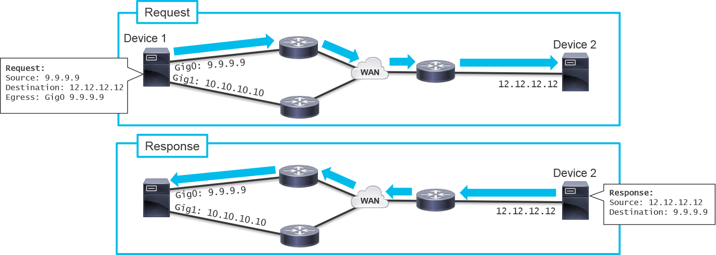
Figure 8-6 A Baseline Working Scenario with good Network Routing
Step 1. Device 1 initiates the communication by checking the local routing and adjacency tables to determine where to send the packet and which interface should be used as the exit interface for the IP address 12.12.12.12. The results show that Gig0 should be used for routing packets to the remote IP address of Device 2.
Step 2. Device 1 builds the request with the source IP address 9.9.9.9 and routes the packet toward the default gateway by using the egress interface Gig0.
Step 3. Device 1’s default gateway receives the packet then routes it to the WAN.
Step 4. The routing steps in the WAN are omitted, but the WAN does contain all the routing information required to send the packet to Device 2’s default gateway.
Step 5. Device 2’s default gateway has no problem sending the packet to Device 2 because they reside on the same LAN.
Step 6. The request is processed by Device 2, and a response should be generated.
In the scenario shown in Figure 8-6, the response involves the following steps:
Step 1. Device 2 builds a response packet with the source IP address 12.12.12.12 and destination address 9.9.9.9 as this was the source of the received request packet. Since Device 2 and Device 1 reside on different networks, the response packet sourced from Device 2 and sent to Device 1 must be sent to the local default gateway for Device 2.
Step 2. Device 2’s default gateway receives the packet and performs a routing lookup to find out where to send the packet. This check determines that a route exists through the WAN.
Step 3. The WAN is easily able to route the packet to Device 1’s default gateway.
Step 4. Device 1’s default gateway and Device 1 are on the same LAN, so routing the packet to Device 1 is easy.
Step 5. The response packet is received, and the communication session completes successfully.
Figure 8-6 illustrates that when a valid Layer 3 IP address routing on the LAN and WAN has been configured, establishing roundtrip sessions between two devices goes well. Figure 8-7 shows exactly the same scenario as Figure 8-6, but in this case, Device 1 sends the packet from the other egress interface, Gig0, with source IP address 10.10.10.10. Device 1 does not know it, but the default gateway for Device 2 was not configured with routing information for 10.10.10.10, so a failure will occur. In the scenario shown in Figure 8-7, you see the following actions for the request:

Figure 8-7 An Example of Bad Network Response Routing
Step 1. Device 1 initiates the communication by checking the local routing and adjacency tables to determine where to send the packet and which interface to use as the exit interface for IP address 12.12.12.12. The results show that Gig1 should be used for routing packets to the remote IP address of Device 2.
Step 2. Device 1 builds the request packet with source IP address 10.10.10.10 and sends the packet out Gig1 toward the default gateway for that LAN segment.
Step 3. The default gateway receives the packet and routes it over the WAN toward Device 2’s default gateway.
Step 4. The WAN has all the information required to properly route the packet to Device 2’s default gateway.
Step 5. Device 2’s default gateway receives the packet and forwards it to Device 2 since they are on the same LAN segment.
Step 6. The request is received successfully, and a response should be generated.
In the scenario illustrated in Figure 8-7, the response involves the following steps:
Step 1. Device 2 builds a response packet with the source IP address 12.12.12.12 and the destination address 10.10.10.10 as this was the source of the received request packet. Because Device 2 and Device 1 reside on different networks, the response packet sourced from Device 2 and sent to Device 1 must be sent to the local default gateway for Device 2.
Step 2. The default gateway receives the packet and performs a routing table lookup to determine where to send this packet. Here is where a problem occurs: There are no default routes on Device 2’s default gateway, and there are no routes for Interface 2 of Device 1’s Gig1 interface IP address 10.10.10.10.
Step 3. Device 2’s default gateway drops the response packet, and the communication session fails because Device 1 does not get a response from Device 2.
The good news is that the scenario illustrated in Figure 8-7 is easy to fix. In fact, there are two ways to solve the problem:
• You can fix routing on LAN 2’s default gateway so that there is a route back to Device 1’s Interface 2.
• You can change the routing on Device 1 to send the packet out Interface 1 rather than Interface 2, thus assuming the IP address assigned to Interface 1 as the source IP address. This allows the remote device’s default gateway to properly route the response packet.
Now you might be wondering why we have all this talk about Layer 3 IP routing in a book about Layer 7 application protocols such as SIP. The fact is, scenarios like this arise all the time in the real world. Response packet routing might not be possible when packets are sourced from a specific network IP address. This situation may arise because of security settings, due to design elements, or because of suboptimal network routing. Additional complexity arises when logical interfaces such as loopback interfaces are in play. If Interface 1 in Figure 8-7 were a loopback rather than a physical interface, the route-changing solution would not be an option because you cannot route packets out a logical interface.
Fortunately, there is a third option: You can use application protocol binding. Application protocol binding involves “spoofing” the source of an application packet to influence response routing at Layer 3. Figure 8-8 illustrates a scenario that follows the same rules as Figure 8-6 and Figure 8-7. Without any protocol binding, the same scenario shown in Figure 8-7 would play out. Fortunately, however, in Figure 8-8, the network administrator has leveraged an application protocol binding command on Device 1 to bind request traffic to Gig0 with the IP address 9.9.9.9.

Figure 8-8 A Sample Scenario Illustrating Good Network Response Routing with Application Protocol Binding
In the scenario illustrated in Figure 8-8, the request involves the following steps:
Step 1. Device 1 initiates the communication by checking the local routing and adjacency tables to determine where to send the packet and which interface to use as the exit interface for IP address 12.12.12.12. The results show that Gig1 should be used for routing packets to the remote IP address of Device 2.
Step 2. Because the administrator leveraged application protocol binding for Gig1, Device 1 spoofs the source of the request packet from that interface while still routing the packet out the physical interface, as per the lookup from step 1.
Step 3. A response packet with the source IP address 9.9.9.9 is created, and the packet is sent out interface Gig1 toward that LAN segment’s default gateway.
Step 4. The default gateway routes across the WAN to LAN 2’s default gateway, as normal, sending the packet to Device 2.
Step 5. The request is processed by Device 2, and a response should be generated.
In the scenario illustrated in Figure 8-8, the response involves the following steps:
Step 1. Device 2 builds a response packet with source IP address 12.12.12.12 and destination address 9.9.9.9 as this was the source of the received request packet. Because Device 2 and Device 1 reside on different networks, the response packet sourced from Device 2 and sent to Device 1 must be sent to the local default gateway for Device 2. Note here that Device 2 does not know that the packet was sent from Gig1. The source has been spoofed to look as if the packet came from Gig0.
Step 2. Regardless of the source IP address of the request packet, because Device 2 and Device 1 reside on different LAN segments, Device 2 must route the response packet to the local default gateway for further routing decisions.
Step 3. Device 2’s default gateway receives the packet and performs a lookup to determine where to route the packet. Because the destination of this response is Gig0 of Device 1, Device 2’s default gateway determines that it must route this response packet across the WAN. This would not be possible without application protocol binding.
Step 4. The rest of the scenario plays out as expected: The LAN 1 default gateway receives the response packet and forwards it to Device 1, which receives the packet on Gig0.
Step 5. Due to the application protocol binding created by the administrator, the response packet is received, and the communication session completes successfully.
Tip
Leveraging application protocol binding on physical interfaces that traverse different network segments such as those shown in Figure 8-8 can increase the chances of asymmetric routing for responses.
![]()
Application protocol binding can be a very valuable tool for any network administrator. For many application protocols, such as TFTP, FTP, HTTP, SIP, H.323, MGCP, and SCCP, IOS binding commands can be leveraged to solve scenarios like the one illustrated in Figure 8-7. For SIP and CUBE, binding can be leveraged in two forms:
• Signaling/control binding: Used to change the source IP address information in Layer 3 packets and Layer 7 SIP headers
• Media binding: Used to change the IP source information observed in the SIP SDP message body
With SIP, binding commands can be applied in multiple places for granular control of calls established through CUBE. IOS examines a configuration in the following order and selects the first configuration found when determining the source address information for the session:
1. Binding commands configured on the dial peer selected for the inbound or outbound call leg
2. Binding commands configured on a voice class tenant, which is then assigned to a dial peer selected for the inbound or outbound call leg
3. Binding commands configured globally via voice service voip and sip, which affect any call leg when the previous two bindings do not exist
When none of the binding commands mentioned previously have been configured, CUBE and IOS leverage both the routing table and adjacency table by way of the Cisco Express Forwarding (CEF) table to determine the egress interface that will be used to route SIP packets to the network address on the session target. This interface’s network information is then used as the source information for the SIP packet. When good IP routing configurations have been put in place and no logical interfaces are used, application protocol binding is not required.
Tip
Remember that when application protocol binding is applied, the application packet only looks as if it was sent from the binding interface when it is received by the remote party. The application packet still egresses through a physical interface, as determined by IOS IP routing logic. When binding is used, always check the routing table and CEF table with show ip route and show ip cef to verify that the packet is being sent out the correct physical interface and to the correct next-hop IP address. Incorrect packet routing on the local device cannot be overcome with application protocol binding that influences response packet routing.
With CUBE, you enable binding with a few simple commands. Example 8-27 shows the binding commands that can be applied for SIP dial peers, voice class tenant commands, and global voice service voip to bind controls (SIP signaling) and media (SDP and RTP) to a specific source interface.
Example 8-27 A Reference Configuration for How to Apply Signaling and Media Binding with CUBE
! Dial-peer Bind, most specific
dial-peer voice 9999 voip
 session protocol sipv2
 voice-class sip bind control source-interface Loopback0
 voice-class sip bind media source-interface Loopback0
!
!  Voice Class Tenant Bind, secondary check
voice class tenant 8888
 bind control source-interface Loopback0
 bind media source-interface Loopback0
!
dial-peer voice 8888 voip
 session protocol sipv2
voice-class sip tenant 8888
!
! Global Bind, applies to all call-legs if the first two do not exist
voice service voip
 sip
  bind control source-interface Loopback0
  bind media source-interface Loopback0
!
Tip
Binding commands for media cannot be changed while there are active CUBE sessions until IOS-XE 17.3.
As mentioned earlier, when no binding is configured, the IOS CEF table is leveraged to determine the egress interface for routing packets to the remote IP address. The remote IP address used in the lookup may be the IP address defined on the dial peer’s session target, or it may be the SIP Via or Contact header IP address from an inbound SIP request. Example 8-28 shows a sample IP configuration, along with a dial peer that has a session target of 172.18.110.48. The CEF table shows that the egress interface is Gig0/0.206, which has source IP address 14.50.244.63. This IP address is used to source the packet sent from this device toward 172.18.110.48. You could leverage application protocol binding to source the packet from Loopback0 while still sending the packet out Gig0/0.206 but without using that as the source IP address.
Example 8-28 show Command Output Showing Which Interface Would Be Used to Send a Packet
rtp-cube# show ip interface brief | e una
Interface                  IP-Address      OK? Method Status                Protocol
GigabitEthernet0/0.206     14.50.206.50    YES manual up                    up
Loopback0                  172.18.110.68   YES NVRAM  up                    up

KYDAVIS-CME-2951# show ip cef 172.18.110.48
172.18.110.48/32
nexthop 14.50.206.1 GigabitEthernet0/0.206
SIP application protocol binding can also be leveraged to change the listening port for UDP, TCP, and TCP TLS traffic sent to CUBE. By default, CUBE always listens for inbound connections on SIP UDP/TCP port 5060 and TLS port 5061. This can be confirmed with the show sip-ua status command or show sip-ua connections {udp | tcp | tcp tls} brief. Example 8-29 shows these verification commands and the inbound listening IP addresses. By default, CUBE listens on all IP addresses for IPv4 and IPv6 (if configured). The listening addresses for IPv4 and IPv6 can be limited or changed by using global binding commands, as described in the previous paragraphs. Inbound UDP, TCP, or TCP TLS can be disabled by adding no transport {udp | tcp | tcp tls} to a sip-ua configuration. For outbound transport types, the configured session transport command is leveraged. CUBE’s default outbound transport type is UDP. Layer 4 UDP, TCP, and TLS CUBE interworking does not require any configuration.
Example 8-29 A Few show Commands That Detail the Listening IP Addresses and Ports for UDP, TCP, and TLS
rtp-cube# show sip-ua status
SIP User Agent Status
SIP User Agent for UDP : ENABLED
SIP User Agent for TCP : ENABLED
SIP User Agent for TLS over TCP : ENABLED
[..Truncated for brevity..]

rtp-cube# show sip-ua connections udp brief
[..Truncated for brevity..]

-------------- SIP Transport Layer Listen Sockets ---------------
  Conn-Id               Local-Address
 ===========    =============================
   0            [0.0.0.0]:5060:
   1            [::]:5060:
rtp-cube# show sip-ua connections tcp brief
[..Truncated for brevity..]

-------------- SIP Transport Layer Listen Sockets ---------------
  Conn-Id               Local-Address
 ===========    =============================
   0            [0.0.0.0]:5060:
   1            [::]:5060:
rtp-cube# show sip-ua connections tcp tls brief
[..Truncated for brevity..]

-------------- SIP Transport Layer Listen Sockets ---------------
  Conn-Id               Local-Address
 ===========    =============================
   0            [0.0.0.0]:5061:
   1            [::]:5061:
Digit, Header, and URI Manipulation
When interfacing with third-party service providers or other SBCs, there is a possibility that differing dial plans may be in use. The digit format used by one party to route a call may not be the format configured on the local endpoints or call processing agents, such as Unified CM. One of the most common examples is the use of the +E.164 dial plan by the service providers while the local LAN is configured with four-digit extensions, where the last four digits of the full +E.164 number are what the endpoint expects to be called. Chapter 1 and Chapter 4 discuss that deploying a globalized dial plan and placing the +E.164 number on the endpoint mitigates the need for these types of digit modifications on inbound calls. On the flip side, most enterprise deployments use an enterprise dial-out number such as 8 or 9, which is prefixed by a user who wants to dial an off-net number. This is used in dial planning on Unified CM and CUBE as a steering code to differentiate calls for endpoints on the network from calls that should be routed to an off-net location such as the ITSP. Because the enterprise dial-out number is used only by LAN endpoints to signal the need to reach the PSTN, most service providers do not want this number prefixed on a call. As a result, it must be stripped from the called number before the call is sent to the service providers. Again, assuming a globalized dial plan is in place this might already have been done by Unified CM and no digit stripping is required on the +E.164 number received by CUBE.
Likewise, SIP headers and URIs may need to be modified or removed to facilitate call routing and interworking with third-party devices. CUBE Enterprise can be leveraged to perform the required interworking for digits, SIP headers, and SIP URIs found in calls traversing the SBC. The next two sections detail how you can leverage translation rules and profiles to modify digits or SIP profiles and how you can use SIP copylists to modify any aspects of a SIP header, including the SIP URI.
Digit Manipulation
![]()
Digit manipulation involves changing the numeric numbers dialed during session establishment from one set of digits to another set of digits. Digit manipulation may be used to change the destination of a called number, change the caller ID of the calling party number, or block numbers entirely. With older IOS analog voice gateways, digit manipulation can occur in many different places. With CUBE, the options are much more limited. In most scenarios, digit manipulation on CUBE involves using voice translation rules and voice translation profiles to modify numeric digits in SIP headers.
Voice Translation Rules and Profiles
The process of creating and applying translation rules and profiles on CUBE involves the following steps:
Step 1. Define a voice translation rule container and individual actionable rules. Such a container can hold up to 100 actionable rules that perform input matches and output modifications based on the input match.
Step 2. Create a voice translation profile to reference a voice translation rule and bind the voice translation rule to a specific type of lookup. The lookups are as follows:
• Called: This type of lookup maps to the user ID in the SIP Request-URI header.
• Calling: This type of lookup maps to the user ID in the SIP From, Remote-Party-ID, P-Asserted-ID, or P-Preferred-ID header.
• Redirect-called: This type of lookup maps to the user ID in the SIP Diversion header.
• Redirect-target: This type of lookup maps to the user ID in the SIP Refer-To header.
• Callback-number: Unified Communications Manager Express uses this type of lookup to modify the callback number shown on an IP phone.
Step 3. The voice translation profile is applied to a dial peer for use with a call leg. Alternatively, a global inbound translation profile can be defined with the command voip-incoming translation-profile.
Example 8-30 shows the syntax for translation rules and translation profiles, and Example 8-31 shows the usage and application of translation profiles in IOS.
Example 8-30 The Command Syntax for Translation Rules and Profiles
!
voice translation-rule numeric-tag
 rule [1-100] /match-statement/ /modify-statement/
!
voice translation-profile word
 translate {called | calling  | redirect-target | redirect-called | callback-number} numeric-tag
!
Example 8-31 The Application of Translation Profiles to Global Configuration or Dial Peers
!
voip-incoming translation-profile word
!
dial-peer voice tag voip
 session protocol sipv2
 translation-profile outgoing word
 translation-profile incoming word
!
Tip
Incoming translation profiles are applied when a dial peer is selected as an inbound dial peer. Outbound translation profiles are applied when the dial peer is selected as an outbound dial peer for a given call leg.
Translation rule match statements use regex that are very similar to the regex and wildcards used with dial peer matching commands (refer to Table 8-3). In addition, voice translation rule match statements have their own wildcards that serve various purposes. Table 8-11 shows the wildcard statements specific to voice translation rule match statements.
Table 8-11 Translation Rule Match Statement Wildcards and Regex

Understanding Match and Modify Statements
As noted in Table 8-11, regex or digits wrapped in parentheses are considered a set. A set is usually escaped to avoid matching a literal ( or ) character. A set can be used to store the matched characters between the parentheses as a variable that can be used later in the modify statement. The sets are then referenced using an escaped number in the modify statement. For example, the very first set in a match statement is referenced with 1 in the modify statement, the next set is 2, and so on. � has a very special purpose of matching everything in the match statement; it is equivalent to the modify statement ampersand wildcard character (&). Example 8-32 shows a few variations using sets. The command test voice translation-rule can be used to test IOS translation rules and view the logic.
Example 8-32 An Example Detailing How Sets and Wildcards Work with Translation Rule Match and Modify Statements
! voice translation-rule 777 rule 1 /^111(222)333(444)555/ /12/ rule 2 /^14085267209/ /+�/ rule 3 /^4085267209/ /+1&/ rule 4 /^9(.*)/ /1/ rule 5 /+(.*)/ /1/ rule 6 /.*(....)/ /1/ ! Router# test voice translation-rule 777 111222333444555
Matched with rule 1
Original number: 111222333444555        Translated number: 222444
Router# test voice translation-rule 777 14085267209
Matched with rule 2
Original number: 14085267209    Translated number: +14085267209
Router# test voice translation-rule 777 4085267209
Matched with rule 3
Original number: 4085267209     Translated number: +14085267209
Router# test voice translation-rule 777 918005532447
Matched with rule 4
Original number: 918005532447   Translated number: 18005532447
Router# test voice translation-rule 777 +14085267209
Matched with rule 5
Original number: +14085267209   Translated number: 14085267209
Router# test voice translation-rule 777 14085151111
Matched with rule 6
Original number: 14085151111 Translated number: 1111
Administrators use everything except rule 1 of the match statement and modify statement examples in Example 8-32 in everyday deployments. Note the following process in Example 8-32:
Step 1. The first rule matches 111222333444555 and specifically has brackets around 222 and 444, which applies them as sets 1 and 2. These two sets are then referenced as 1 and 2, which change the number 2224444.
Step 2. The second rule matches 14085267209 and adds a leading plus character (+). The � is the wildcard for set 0, which references everything in the match statement.
Step 3. The third rule accomplishes the same thing but with a match of 4085267209. The modify statement adds a +1 prefix and uses the ampersand (&) wildcard to leverage everything found in the match statement.
Step 4. The fourth rule matches anything with a leading 9 and any other character designated by the dot (.) and asterisk (*). This is then grouped into set 1 and used in the modification statement. Since the 9 was not part of the set grouping, it is effectively stripped from the number. (This is a very common translation profile to apply in CUBE.)
Step 5. The fifth statement matches a literal plus (+) by escaping the character. If the plus were not escaped, it would be treated as a regex plus. The plus is then stripped by referencing set 1, which matches anything else in the number string with .*.
Step 6. The last statement illustrates how to strip a given input to a specific length, starting with the right-justified digits. In this case, 14085151111 becomes 1111 because the match statement matches any character and then assigns the last four digits of the numeric string as set 1.
Keep in mind that translation rule match statements are evaluated from the top down, like access control lists (ACLs). When an applicable match statement is found on a given rule, the hunting stops, and the modification statement is applied. No further rules are examined. You should order translation rule match statements so that more exact match statements are given lower rule numbers to ensure they appear higher in the list. The more inclusive regex match statements should be at the bottom of the list, by applying a larger rule number, to avoid greedily matching numbers they should otherwise not match and modify. To illustrate this, in Example 8-33, rule 1 shows an all-inclusive dot star match (.*). This is the regex equivalent of saying that anything goes. Rule 2 matches on 14085267209, but because the greedy match on rule 1 literally matches any value provided to the translation rule, IOS will never match rule 2.
Example 8-33 A Sample Translation Rule Illustrating Greedy Matches Affecting the Ability to Match Rules Further Down the List
voice translation-rule 666 rule 1 /.*/ /8675309/ rule 2 /^14085267209/ /+�/ Router# test voice translation-rule 666 14085267209
Matched with rule 1
Original number: 14085267209    Translated number: 8675309
Router# test voice translation-rule 666 9849848994489
Matched with rule 1
Original number: 9849848994489  Translated number: 8675309
Router# test voice translation-rule 666 AAAA
Matched with rule 1
Original number: AAAA   Translated number: 8675309
Blocking Calls with Translation Rules
As mentioned earlier in this chapter, translation rules can be used to block numbers. These rules use the same command syntax you are already familiar with, but the modify statement is dropped, and the match statement is prefixed with the reject statement. Example 8-34 shows the syntax for blocking a call on CUBE using translation rules. Notice that the translating profile is applied to the dial peer by using the call-block translation-profile incoming command, and the call-block disconnect-cause incoming command specifies the type of block reason signaled to the calling party.
Example 8-34 Command Syntax for Defining Call Blocking Using Translation Rules and Profiles
!
voice translation-rule numeric-tag
 rule 1 reject /match-statement/
!
voice translation-profile profile-name
 translate calling numeric-tag
!
dial-peer voice dial-peer-tag voip
 call-block translation-profile incoming profile-name
 call-block disconnect-cause incoming { call-reject | invalid-number | unassigned-number | user-busy}
!
Table 8-12 provides a mapping between the disconnect reason, SIP Response header, and Q.850 cause code.
Table 8-12 The Mapping of Disconnect Causes to SIP Responses and Q.850 Cause Codes

Note
voip-incoming translation-profile applies translations before the inbound dial peer match is made, which may affect call block matching on the inbound dial peer.
To test a translation rule for blocking calls, you can use the same test command used in the previous examples. Example 8-35 shows a block on the pattern 8675309 in addition to the application of this block pattern to a dial peer.
Example 8-35 A Sample Configuration and Verification of a Blocked Number on an Inbound Dial Peer
!
voice translation-rule 164
 rule 1 reject /8675309/
!
voice translation-profile CALLBLOCK
 translate calling 164
!
dial-peer voice 164 voip
 call-block translation-profile incoming CALLBLOCK
 call-block disconnect-cause incoming invalid-number
!

Router# test voice translation-rule 164 8675309
8675309 blocked on rule 1
Troubleshooting Voice Translations
When the test voice translation-rule command does not suffice, you might need to perform live debugging and examine the logic of debug voice translation. You can run this command along with other commands, such as debug ccsip messages and debug voip ccapi inout. Example 8-36 shows a very simply translation on an incoming SIP INVITE message that checks four match rules and finds a match on the last rule. This rule then modifies the called number in the SIP Request-URI from 4444 to 1234.
Example 8-36 Debugging Output Showing the Logic for Voice Translation Rules and Profiles
020464: Sep 21 17:42:31.023: //-1/xxxxxxxxxxxx/SIP/Msg/ccsipDisplayMsg:
Received:
INVITE sip:4444@172.18.110.58:5060 SIP/2.0

020528: Sep 21 17:42:31.028: //-1/054D9FB28175/RXRULE/regxrule_profile_translate_internal: number=4444 type=unknown plan=unknown numbertype=called
020529: Sep 21 17:42:31.028: //-1/054D9FB28175/RXRULE/regxrule_match: No match; number=4444 rule precedence=1
020530: Sep 21 17:42:31.028: //-1/054D9FB28175/RXRULE/regxrule_match: No match; number=4444 rule precedence=2
020531: Sep 21 17:42:31.028: //-1/054D9FB28175/RXRULE/regxrule_match: No match; number=4444 rule precedence=3
020532: Sep 21 17:42:31.028: //-1/054D9FB28175/RXRULE/regxrule_profile_match_internal: Matched with rule 4 in ruleset 999
020540: Sep 21 17:42:31.028: //-1/054D9FB28175/RXRULE/sed_subst: Successful substitution; pattern=4444 matchPattern=4444 replacePattern=1234 replaced pattern=1234
When non-numeric values are being used, translation rule match statements lose their ability to match effectively. This is very common in SIP, where the user ID portion of a header can be an alphanumeric entry. For such scenarios, a match and modification with voice class SIP profiles should be leveraged. The next few sections cover how to perform SIP header manipulation.
SIP Header Interworking
A SIP header has the following format:
Header: Value
The contents of Value in a SIP header can be almost anything. The goal of a SIP header is to carry data and provide the data in a consumable manner to the next-hop application, which handles the parsing of the SIP message. Many RFCs pertaining to SIP define required and optional SIP headers; in addition, there are vendor-proprietary headers and custom application headers. From an SBC’s perspective, it is nearly impossible to incorporate support for parsing, understanding, and interpreting every possible SIP header in existence.
RFC 3261 details a small list of required headers for every SIP request or SIP response. However, for most SBCs, there is a list of additional supported headers that are considered mandatory to handle SIP messages and session establishment. All headers outside this list are unsupported and may be dropped when creating additional requests and responses during session establishment. There is a problem here: Every SBC vendor or service provider may have a slightly different list of mandatory headers that need to be present for a session to successfully complete with another device.
Sometimes specific headers need to be passed seamlessly across an SBC, possibly without modification. Alternatively, there may arise a situation in which a specific header should not be sent across an SBC because the inclusion of a specific header may cause the upstream device to handle a session incorrectly, terminate a call prematurely, or behave in some other undesired fashion. This means the ability of an SBC to interwork headers from many different device types is of paramount importance.
Note
The Cisco document “Configurable Pass-Through of SIP INVITE Parameters” details the supported mandatory and supported non-mandatory CUBE headers .
Table 8-13 details many of the most common SIP headers that need to be interworked through CUBE. These headers are so important that each one has its own CLI command.
Table 8-13 Common SIP Headers

Tip
The command header-passing is often mistakenly configured on CUBE, although this command has no bearing on any SIP–SIP header interworking. This command is used to allow the passing of SIP headers to IOS-based TCL applications, which otherwise do not have access to such information.
In addition to the explicit CLI commands for the specific headers listed in Table 8-13, CUBE enables you to configure passthrough of any unsupported SIP header, as shown in Example 8-37. If a more refined approach is desired, rather than passing every unsupported header, you can define a list of unsupported headers that can be passed by using the commands shown in Example 8-38.
Example 8-37 Passthrough of Unsupported SIP Headers
voice service voip
 sip
pass-thru headers unsupp
Example 8-38 Defined List of Unsupported Headers
voice service voip
 sip
pass-thru headers 1
!
voice class sip-hdr-passthrulist 1
 passthru-hdr MyCustomHeader
 passthru-hdr-unsupp
Even more granularity is possible through the use of SIP profiles and SIP copylists, which allow you to add custom headers and manipulate not only SIP headers but anything in a SIP message. The next section dives into this topic.
SIP Normalization
With SIP normalization, a user agent manipulates SIP headers, header data, or SDP attributes. The need to modify portions of a SIP message may arise in a number of different scenarios, such as when formatting header fields to the preference of upstream devices, adding proprietary data to a SIP message, or modifying received SIP messages to enable smooth processing.
A SIP message, including the SIP headers and message bodies (for example, SDP), contains plaintext data. As a result, with SIP profiles you use regex to match portions of a SIP message and modify the matched portions to meet your needs. This process is similar to the translation rules and profiles discussed earlier in this chapter. The big difference is that a SIP profile is not constrained to just a phone number. For example, a message received from a device might contain a SIP header that is malformed or incorrectly formatted, and processing such a message could lead to unexpected behavior. SIP normalization is an effective tool for modifying such messages and ensuring that they are correctly formatted before processing.
![]()
SIP normalization is usually broken down into two main categories: preprocessing normalization and postprocessing normalization. Figure 8-9 displays both forms of SIP normalization and details the flow of operations for each. With preprocessing normalization, the following events occur:

Figure 8-9 Pre- and Postprocessing SIP Normalization
Step 1. The SIP message is received by the SBC as an IP packet.
Step 2. The SIP message is extracted from the IP packet and passed on to the SIP application.
Step 3. The SIP application performs the required preprocessing normalization, based on locally configured policies.
Step 4. The normalized message is passed on to the SIP stack, and the message is then interpreted for processing.
Step 5. Based on the results of processing, further action is performed. This could include immediately sending a response, passing the message to the peer call leg, or formulating a new request.
With postprocessing normalization, the following events occur:
Step 1. The SIP stack performs local logic, such as forming a new request or handling a message from the peer call leg.
Step 2. New SIP message data is created, and existing data from the peer leg may be added to the newly created SIP message. This message is then passed to the SIP application.
Step 3. The SIP application performs the required postprocessing normalization, based on locally configured policies.
Step 4. The normalized SIP message is encapsulated for transport over the LAN as an IP packet.
Step 5. The IP packet containing the SIP message is put on the wire and sent to the next hop.
SIP Profile Configuration
You configure a SIP profile by defining voice-class sip profile profile-id, where profile-id is a numeric identifier for the configured SIP profile. You can add statements to a SIP profile, where each statement consists of a request or a numbered response, the specific message being modified, a header type, and the actual header name. With a SIP profile, you can modify, add, or remove SIP message data. Example 8-39 and Table 8-14 show the command syntax used to configure a SIP profile for SIP header or SDP modification.
Example 8-39 SIP Profile Syntax Used for Header Modification
!
voice-class sip profile profile-id
 {request | response} message {sip-header | sdp-header} header-to-modify modify “value-to-match” “value-to-replace"
!
Table 8-14 SIP Profile Modification Syntax

You can also use SIP profiles to add proprietary headers to SIP messages. You do this by using the ADD statement in a SIP profile. The ability to add custom headers was introduced in IOS 15.5(2)T and IOS XE 3.13S. Example 8-40 and Table 8-15 show the command syntax for adding a SIP header or an SDP value to a SIP message.
Example 8-40 SIP Profile Syntax Used for Adding Headers
!
voice-class sip profile profile-id
 {request | response} message {sip-header | sdp-header} header-to-add add “value-to-add"
!
Table 8-15 SIP Profile Addition Syntax

You can also use a SIP profile to remove a value from a SIP message. This is a very powerful way of dropping headers that may be causing interworking issues. Example 8-41 and Table 8-16 detail the command syntax for header removal.
Example 8-41 SIP Profile Syntax Used for Removing Headers
!
voice-class sip profile profile-id
 {request | response} message {sip-header | sdp-header} header-to-remove remove
!
Table 8-16 SIP Profile Removal Syntax
Once a SIP profile has been defined, it can be applied to the global configuration under voice service voip and the SIP subsection, which allows for the profile to be run against any SIP message, regardless of the dial peers used. Global application of SIP profiles is also useful when you need to manipulate SIP messages that do not use dial peers (for example, SIP REGISTER messages, OOD OPTIONS messages). SIP profiles can also be applied to voice class tenant configurations or dial peers for more granular control of SIP messages on a per-call basis.
Example 8-42 shows the different levels of profile application. One thing to keep in mind is the order of operations for SIP profiles and that SIP profiles defined on a dial peer/tenant take precedence over a global SIP profile when they are modifying the same item.
Example 8-42 Different SIP Profile Application Levels
! Global Application
!
voice service voip
 sip
sip-profiles 1
!
! Tenant Application
!
voice class tenant 1
sip-profiles 1
!
! Dial-peer Application
!
dial-peer voice 1 voip
voice-class sip profiles 1
!
Outbound SIP Profiles
Outbound SIP profiles are the most common type of SIP profile used in CUBE deployments. These SIP profiles follow the postprocessing normalization process defined earlier in this chapter (refer to Figure 8-9). This modification occurs after call routing decisions are made and before the SIP message is placed on the wire and sent to the next hop as an IP packet. This modification can be applied to both SIP requests and responses as well as SIP headers and an SDP body.
A common use case of outbound SIP profiles is for adding or modifying a SIP Diversion header sent in an egress SIP INVITE message for authentication by an upstream device, such as a proxy or an ITSP. The SIP profile in this use case would be added to the outbound dial peer so that CUBE can modify the egress INVITE message before actually sending the message to the user agent that requires the header. Example 8-43 shows the configuration for the addition of a Diversion header. This method can be used when no Diversion header is received on the other call leg. Example 8-44 shows the modification performed by CUBE that takes place in this scenario.
Example 8-43 Adding a Diversion Header to an Egress INVITE Message
!
voice class sip-profiles 777
 request INVITE sip-header Diversion add “Diversion: <sip:[email protected]>"
!
dial-peer voice 777 voip
 destination-pattern 7777
 session protocol sipv2
 session target ipv4:172.18.110.65
voice-class sip profiles 777
codec g711ulaw
Example 8-44 shows debugging information for the configuration shown in Example 8-43. Notice the outbound dial peer match 777. This is where the outbound SIP profile is applied. Thus the addition of the new header occurs when the SIP profile is executed on the SIP INVITE request. The new SIP message containing the added header is then put on the wire and sent on the network.
Example 8-44 Debugging for Adding a Diversion Header
May 19 21:05:57.762: //125/6B6A2E000000/CCAPI/ccCallSetupRequest:
   Guid=6B6A2E00-0001-0000-0000-001A306E12AC, Outgoing Dial-peer=777

May 19 21:05:57.762: //-1/xxxxxxxxxxxx/SIP/Info/info/64/sipSPISetSipProfilesTag: voice class SIPProfiles tag is set : 777
May 19 21:05:57.763: //-1/xxxxxxxxxxxx/SIP/Info/info/64/sip_profiles_application_change_sip_headers:  New header added to the SIP message : Diversion: <sip:[email protected]>

May 19 21:05:57.764: //126/6B6A2E000000/SIP/Msg/ccsipDisplayMsg:
Sent:
INVITE sip:[email protected]:5060 SIP/2.0
[..Truncated for brevity..]
Diversion: <sip:[email protected]>
The previous two examples detail a situation in which a Diversion header is not present on the ingress SIP messaging. If a Diversion header is received on the ingress call leg, CUBE passes the Diversion header through to the outbound call leg. Example 8-45 shows how to modify a Diversion header that was received and passed through CUBE. Example 8-46 shows the received Diversion header field, CUBE SIP profile modification, and egress SIP message after modification. A good rule to remember is that a modification always occurs on a header that is present either by default or by being passed from one call leg to another.
Example 8-45 Modifying a Diversion Header in an Egress INVITE Message
!
voice class sip-profiles 888
 request INVITE sip-header Diversion modify “sip:(.*)>” “sip:[email protected]>"
!
dial-peer voice 888 voip
 destination-pattern 7777
 session protocol sipv2
 session target ipv4:172.18.110.65
voice-class sip profiles 888
codec g711ulaw
Example 8-46 shows the debugging for the configuration in Example 8-45. Notice that the outbound dial peer match occurs on dial peer 888, where the outbound SIP profile is applied. Because you receive an inbound SIP request with a Diversion header, this is going to be passed through CUBE and included in the outbound SIP request. The SIP profile is then able to modify that header because it is present in the outbound request. The final SIP message containing the modification is then put on the wire and sent across the network.
Example 8-46 Debugging Information for Modifying a Diversion Header
Sent:
INVITE sip:[email protected]:5060 SIP/2.0
[..Truncated for brevity..]
Diversion: <sip:[email protected]>;privacy=off;reason=unconditional;screen=yes
May 19 21:13:27.416: //147/77A2BB000000/CCAPI/ccCallSetupRequest:
   Guid=77A2BB00-0001-0000-0000-001D306E12AC, Outgoing Dial-peer=888
May 19 21:13:27.417: //-1/xxxxxxxxxxxx/SIP/Info/info/64/sipSPISetSipProfilesTag: voice class SIPProfiles tag is set : 888

May 19 21:13:27.418: //-1/xxxxxxxxxxxx/SIP/Info/info/64/sip_profiles_application_modify_remove_header: Header before modification : Diversion: <sip:[email protected]>;privacy=off;reason=unconditional;screen=yes
May 19 21:13:27.418: //-1/xxxxxxxxxxxx/SIP/Info/info/64/sip_profiles_application_modify_remove_header: Header after modification : Diversion: <sip:[email protected]>;privacy=off;reason=unconditional;screen=yes

Sent:
INVITE sip:[email protected]:5060 SIP/2.0
[..Truncated for brevity..]
Diversion: <sip:[email protected]>;privacy=off;reason=unconditional;screen=yes
A common misconception is that an outbound SIP profile can only be applied to an outbound dial peer. This is not the case. The term outbound SIP profile references the direction of SIP messaging that needs modification. For example, you might need to modify an outbound SIP message on an inbound call leg. You achieve this by applying the defined SIP profile to an inbound dial peer that is anchored to the call leg where you need to modify outbound SIP messaging.
An example of this use case would be changing a 100 Trying message sent from CUBE to a 100 Giving a Try message. The 100 Trying response is always sent after CUBE matches an inbound dial peer, and because this is an egress SIP message—from CUBE to the previous hop—this is where you would apply an outbound SIP profile. Example 8-47 shows the configuration needed to perform outbound SIP message modification on an inbound dial peer, and Example 8-48 shows the outbound SIP 100 Provisional response and the outbound SIP profile modification applied to this egress message. All of this is done by applying an outbound SIP profile to an inbound dial peer.
Example 8-47 Outbound SIP Profile on an Inbound Dial Peer
!
voice class sip-profiles 164
 response 100 sip-header SIP-StatusLine modify “100 Trying” “100 Giving a Try"
!
dial-peer voice 222 voip
 description INBOUND DIAL-PEER
 session protocol sipv2
 incoming called-number 7777
voice-class sip profiles 164
 dtmf-relay rtp-nte
 codec g711ulaw
Example 8-48 shows the debugging information for the configuration in Example 8-47. Notice the inbound dial peer match 222. This is where the outbound SIP profile is defined. CUBE attempts to send a 100 Trying response to the previous hop in order to let that UAC know that it is currently processing the message. Because you have an outbound SIP profile, it is first executed against the 100 Trying message. The message matches the statement and changes the value of the status line to 100 Giving a Try. The message is then put on the wire and sent across the network.
Example 8-48 Debugging Information from an Outbound SIP Profile on an Inbound Dial Peer
May 19 21:00:49.005: //-1/B33C85800000/CCAPI/cc_api_call_setup_ind_common:
   Incoming Dial-peer=222, Progress Indication=NULL(0), Calling IE Present=TRUE,

May 19 21:00:49.004: //-1/xxxxxxxxxxxx/SIP/Info/info/64/sipSPISetSipProfilesTag: voice class SIPProfiles tag is set : 164
May 19 21:00:49.005: //109/B33C85800000/SIP/Info/info/64/sip_profiles_application_modify_stat_line: Status-Line before modification : SIP/2.0 100 Trying
May 19 21:00:49.005: //109/B33C85800000/SIP/Info/info/64/sip_profiles_application_modify_stat_line: Status-Line after modification : SIP/2.0 100 Giving a Try

Sent:
SIP/2.0 100 Giving a Try
Via: SIP/2.0/TCP 172.18.110.48:5060;branch=z9hG4bK3ce13e40fa2
From: <sip:[email protected]>;tag=23232~1992ce86-77ac-43a7-91b7-90778966a9f5-30207641
To: <sip:[email protected]>
Call-ID: [email protected]
CSeq: 101 INVITE
Content-Length: 0
Inbound SIP Profiles
Like their outbound counterparts, inbound SIP profiles are used to manipulate aspects of a SIP message, including SIP headers and the SDP body. The syntax of an inbound SIP profile is exactly the same as that of an outbound SIP profile. The main differences between inbound and outbound SIP profiles are in their use and application.
Inbound SIP profiles modify ingress messages on CUBE globally or for each dial peer. Just as with outbound SIP profiles, you can apply an inbound SIP profile to an inbound or outbound dial peer. Inbound SIP profiles allow you to modify a SIP message before CUBE processes the message. This gives you great flexibility in modifying SIP messages and SDP bodies of inbound traffic before the traffic is actually processed by CUBE.
Inbound SIP profile support must be enabled globally before the feature can be used on a SIP message (see Example 8-49).
Example 8-49 Enabling Inbound SIP Profile Support
voice service voip
 sip
sip-profiles inbound
When inbound SIP profile support is enabled, you can start the process of defining a SIP profile. When the definition of the desired SIP profile is complete, you apply it to either global configuration or dial peers by postfixing the keyword inbound to the normal sip-profile command, as shown in Example 8-50.
Example 8-50 Applying an Inbound SIP Profile
! Global Application
!
voice service voip
 sip
sip-profiles 555 inbound
!
! Dial-peer Application
!
dial-peer voice 555 voip
voice-class sip profiles 555 inbound
!
Examples 8-51 and 8-52 show an inbound SIP profile being used to convert a received Date header in a SIP INVITE message from EST to GMT. RFC 3261 explicitly states that Date headers must be in the GMT format, and the reception of a nonstandard Date header would cause this call to fail. You can use an inbound SIP profile to perform the desired modification on the Date header before the CUBE application processes the message and, as a result, avoid undesired session termination.
Example 8-51 Configuring an Inbound SIP Profile
voice service voip
 sip
sip-profiles inbound
!
voice class sip-profiles 111
 request ANY sip-header Date modify “EST” “GMT"
!
dial-peer voice 1 voip
 session protocol sipv2
 incoming called-number 1234
voice-class sip profiles 111 inbound
codec g711ulaw
Example 8-52 shows the debugging information for the configuration in Example 8-51. Here you can see a received INVITE message with a Date header containing the problematic EST value. An inbound dial peer match occurs, and the inbound SIP profile defined on that dial peer is triggered. As a result, the EST is changed to GMT. This is all done before the SIP message is parsed by the SIP stack, thus circumventing the failure that may occur without the manual change to this header.
Example 8-52 Debugging Information for an Inbound SIP Profile
Received:
INVITE sip:[email protected]:5060 SIP/2.0
Via: SIP/2.0/UDP 172.18.110.65:5060;branch=z9hG4bK-16095-1-0
From: <sip:[email protected]:5060>;tag=1
To: sut <sip:[email protected]:5060>
Call-ID: [email protected]
CSeq: 1 INVITE
Contact: sip:[email protected]:5060
Max-Forwards: 70
Supported: timer
Date: Fri, 25 May 2018 21:01:13 EST
Session-Refresh: 1800;refresher=uac
Subject: Performance Test
Content-Type: application/sdp
Content-Length:   130

v=0
o=user1 53655765 2353687637 IN IP4 172.18.110.65
s=-
c=IN IP4 172.18.110.65
t=0 0
m=audio 6000 RTP/AVP 0
a=maxptime:20

May 25 21:07:12.568: //-1/xxxxxxxxxxxx/SIP/Info/verbose/64/ccsip_inbound_profile_populate_callinfo_in_ccb: Dial-peer 1 is used for inbound profiles config
May 25 21:07:12.568: //-1/xxxxxxxxxxxx/SIP/Info/info/64/sipSPISetSipProfilesTag: voice class SIP Profiles inbound tag is set : 111
May 25 21:07:12.568: //-1/xxxxxxxxxxxx/SIP/Info/info/64/sip_profiles_application_modify_remove_header: Header before modification : Date: Fri, 25 May 2018 21:01:13 EST
May 25 21:07:12.568: //-1/xxxxxxxxxxxx/SIP/Info/info/64/sip_profiles_application_modify_remove_header: Header after modification : Date: Fri, 25 May 2018 21:01:13 GMT
SIP Copylist
A SIP copylist is a special type of SIP profile that allows CUBE to copy contents from a SIP header as a variable that is stored in memory for later use. The value of this variable can then be used in an outbound SIP profile to manipulate SIP message data.
A SIP copylist can be used to expand on the Diversion header example previously demonstrated in the discussion of outbound SIP profiles. The application of a copylist in this example allows the modification statements to use a variable rather than statically defined data. Subsequently, this variable acts as a placeholder for a large number of potential patterns. Example 8-53 shows a sample configuration in which the copylist copies the user in the From header URI of the ingress INVITE message. CUBE then stores that value as variable u01. Then, by referencing this variable in the outbound SIP profile statement, the outbound SIP profile can be made to operate with potentially limitless patterns, as long as the patterns follow a specific syntax that allows the regex to properly match. When the outbound SIP profile executes its logic, it inserts the data from the variable u01. Example 8-54 displays the entire process and debugging for the full copylist scenario.
Example 8-53 SIP Copylist Example for a Diversion Header
!
voice class sip-copylist 2
 sip-header From
!
dial-peer voice 2 voip
 voice-class sip copy-list 2
!
voice class sip-profiles 888
 request INVITE peer-header sip From copy “<sip:(.*)@” u01
 request INVITE sip-header Diversion modify “sip:(.*)>” “sip:[email protected]>"
!
dial-peer voice 888 voip
 voice-class sip profiles 888
!
Example 8-54 shows the debugging information from CUBE for the configuration shown in Example 8-53. Here you can see a received INVITE with the From header containing user 1027. An inbound dial peer match occurs, and the SIP copylist is applied. You can see that the SIP copylist executes and successfully matches the value 1027, as you would expect. This value is then stored as variable u01 for later use. Outbound dial peer matching occurs, and the SIP profile defined on that dial peer is executed. The value from the u01 variable is then substituted in the SIP profile, which means 1027 is now placed in the Diversion header. Finally, you see the outbound SIP INVITE and modified Diversion header sent to the next hop, and the header contains the 1027 value copied from the inbound INVITE message's From header.
Example 8-54 Debugging Information for the SIP Copylist for a Diversion Header
Received:
INVITE sip:[email protected]:5060 SIP/2.0
Via: SIP/2.0/TCP 172.18.110.48:5060;branch=z9hG4bK3e82ddee05f
From: <sip:1027@172.18.110.48>;tag=23337~1992ce86-77ac-43a7-91b7-90778966a9f5-30207669

May 19 21:37:58.510: //-1/E46B84800000/CCAPI/cc_api_call_setup_ind_common:
   Incoming Dial-peer=2, Progress Indication=NULL(0), Calling IE Present=TRUE,

May 19 21:37:58.512: //201/E46B84800000/CCAPI/ccCallSetupRequest:
   Guid=E46B8480-0001-0000-0000-0020306E12AC, Outgoing Dial-peer=888

May 19 21:37:58.513: //-1/xxxxxxxxxxxx/SIP/Info/info/64/sipSPISetSipProfilesTag: voice class SIPProfiles tag is set : 888
May 19 21:37:58.513: //-1/xxxxxxxxxxxx/SIP/Info/info/64/sip_profiles_prefix_slash_in_copy_var_val: ret_dst: 1027
May 19 21:37:58.513: //202/E46B84800000/SIP/Info/info/64/sip_profiles_application_peer_copy_pattern: SIP Profiles COPY variable: u01 val: 1027
May 19 21:37:58.514: //-1/xxxxxxxxxxxx/SIP/Info/info/64/sip_profiles_application_modify_remove_header: Header before modification : Diversion: <sip:[email protected]>;privacy=off;reason=unconditional;screen=yes
May 19 21:37:58.514: //202/E46B84800000/SIP/Info/info/64/sip_profiles_check_and_get_variables_in_replace_pattern: Node found: COPY variable: u01 val: 1027
May 19 21:37:58.514: //202/E46B84800000/SIP/Info/info/64/sip_profiles_check_and_get_variables_in_replace_pattern: substituted_replace_pattern : sip:1027
May 19 21:37:58.514: //202/E46B84800000/SIP/Info/info/64/sip_profiles_check_and_get_variables_in_replace_pattern: configured_replace_pattern : @example.com>
May 19 21:37:58.514: //202/E46B84800000/SIP/Info/info/64/sip_profiles_check_and_get_variables_in_replace_pattern: Final substituted_replace_pattern : sip:[email protected]>
May 19 21:37:58.514: //-1/xxxxxxxxxxxx/SIP/Info/info/64/sip_profiles_application_modify_remove_header: Header after modification : Diversion: <sip:[email protected]>;privacy=off;reason=unconditional;screen=yes

May 19 21:37:58.514: //202/E46B84800000/SIP/Msg/ccsipDisplayMsg:
Sent:
INVITE sip:[email protected]:5060 SIP/2.0
[..Truncated for brevity..]
Diversion: <sip:[email protected]>;privacy=off;reason=unconditional;screen=yes
Common SIP Profiles
You might need to modify the URI of a SIP header to meet specific formatting requirements of the next hop. Example 8-55 shows how to modify the user portion, the host portion, or the entire URI. This modification can be used for any SIP header and is not limited to the Contact header.
Example 8-55 Modifying the User, Host, or Entire URI in a SIP Header
! User
!
voice class sip-profiles 1
 request ANY sip-header Contact modify “sip:(.*)@” “sip:7777@"
!
! Host
!
voice class sip-profiles 2
 request ANY sip-header Contact modify “@10.10.10.10>” “@example.com>"
!
! Modify the full URI, Both User and Host
!
voice class sip-profiles 3
 request ANY sip-header Contact modify “sip:(.*)>” “sip:[email protected]>"
!
A situation may arise in which you need to modify the received caller name in a SIP header. Normally this would happen if a caller ID (CLID) name such as Anonymous or Unknown is being received in a SIP message. The caller ID name is displayed in a SIP message as a quoted string between the specific header and the SIP URI, as shown here:
From: “MY CLID NAME” <sip:[email protected]>
Example 8-56 shows a way to match everything in the quotes within the content of the From header. The modification statement produces TEST CLID as the output in the From header content.
Example 8-56 Modifying the Caller ID Name
voice class sip-profiles 123
 request INVITE sip-header From modify “".*"” “"TEST CLID*""
Tip
The command clid strip can be defined under a dial peer to remove the caller ID name if removal rather than modification is desired.
If you do not want to advertise update capabilities on CUBE for a specific call leg, you can use the code in Example 8-57 to remove the UPDATE extension from the Allow header. The result of this SIP profile is that the SIP messages sent do not contain the UPDATE entry in the Allow header. Thus, a device receiving the message should not send an UPDATE message to this SBC for any reason.
Example 8-57 Removing UPDATE Advertisement on CUBE
voice class sip-profiles 200
 request ANY sip-header Allow-Header modify “, UPDATE” “"
 response ANY sip-header Allow-Header modify “, UPDATE” “"
You might experience a situation in which sending one of the hold methods defined in the hold/resume section produces issues with a remote device. Example 8-58 defines different methods of modifying the audio media attributes for a=sendonly or a=inactive and replacing them with a=sendrecv. The use of a pipe character (|) is the regex OR method and essentially presents a list of alternatives. Thus, the statement is looking for either audio direction attribute (a=) in parentheses, and if either is present, the modification takes place.
In addition, Example 8-58 details how to change the connection address that is all zeros, 0.0.0.0, to a real IP address. This can be defined for both requests and responses, depending on the direction of messaging that needs to be modified. You could, for example, replace 10.10.10.10 with the desired IP address.
Example 8-58 Hold/Resume or Audio Interop with a Provider
voice class sip-profiles 300
 request ANY sdp-header Audio-Attribute modify “(a=sendonly|a=inactive)” “a=sendrecv"
 request ANY sdp-header Audio-Connection-Info modify “0.0.0.0” “10.10.10.10"
 response ANY sdp-header Audio-Attribute modify “(a=sendonly|a=inactive)” “a=sendrecv"
 response ANY sdp-header Audio-Connection-Info modify “0.0.0.0” “10.10.10.10"
Example 8-59 shows how to insert the option user=phone into any To header in a SIP request or response. This example also details the concept of a set. Each set in regex is a grouping of data within a pair of parentheses. In Example 8-59, the SIP profile is grabbing everything between the < and > characters and storing it as set 1. The 1 is a back reference that allows IOS or IOS XE to call the data from the set 1 that was previous stored. Up to nine unique sets can be used within a SIP profile. The data in a set correlates with the order in which the data appears in a match statement.
Example 8-59 Modifying a To Header with Sets
voice class sip-profile 400
 request ANY sip-header To modify “<(.*)>” “<1;user=phone>"
 response ANY sip-header To modify “<(.*)>” “<1;user=phone>"
Later versions of CUBE allow a user to define a rule tag on a SIP profile. This capability was added to allow for the definite ordering of SIP profile statements and to facilitate quicker modification of statements. Without a rule tag, you must delete the statement and then add it back; otherwise, the statement is duplicated and placed at the end of the current list of statements. Example 8-60 shows a simple SIP profile with rule tags. This example also shows the modification of a SIP header into its shorthand form.
Example 8-60 A SIP Profile with Three Rules
voice class sip-profiles 1234
 rule 1 request INVITE sip-header From modify “From:” “f:"
 rule 2 request INVITE sip-header To modify “To:” “t:"
 rule 3 request INVITE sip-header Contact modify “Contact:” “m:"
The commands voice sip sip-profiles downgrade and voice sip sip-profiles upgrade can be used to either remove or add the rule statements from previously configured SIP profiles. Example 8-61 shows the use of these commands.
Example 8-61 Dynamic Rule Tag
CUBE# voice sip sip-profiles upgrade
CUBE# show run | section 1234
voice class sip-profiles 1234
 rule 1 request INVITE sip-header From modify “From:” “f:"
 rule 2 request INVITE sip-header To modify “To:” “t:"
 rule 3 request INVITE sip-header Contact modify “Contact:” “m:"

CUBE# voice sip sip-profiles downgrade
CUBE# show run | section 1234
voice class sip-profiles 1234
 request INVITE sip-header From modify “From:” “f:"
 request INVITE sip-header To modify “To:” “t:"
 request INVITE sip-header Contact modify “Contact:” “m:"
Tip
It is important to note that if rule tags are being used and you downgrade IOS to a version where rules tags are not present, the SIP profile will be lost. The rule tag command was introduced in IOS 15.5(2)T and IOS XE 3.15S. It is recommended to issue the voice sip sip-profiles downgrade command before downgrading software versions.
Troubleshooting SIP Profiles
SIP profiles allow for granular control over SIP messages, but improper configuration can lead to incorrect formatting of SIP messages, SIP headers, or SDP. Always refer to the applicable RFCs when manipulating any SIP messages to avoid violating the standard formatting of a header and causing undesired call failures. If a modified SIP message is no longer RFC compliant, an upstream device may respond with a 400 Bad Request or another 4xx client-level error indicating that the modification is not accepted.
Use the following debug commands to triage and troubleshoot SIP profile configuration and configuration issues:
debug ccsip messages
debug ccsip info
debug ccsip feature sip-profile
debug voip ccapi inout
debug voip uri
You can also leverage the Cisco SIP-Profile Test tool (see ) to test SIP profiles without the need to make any changes to a device or perform test calls. As shown in Figure 8-10, to use this tool, you input the SIP message you would like to modify, along with the proposed SIP profile. The tool then runs the SIP profile against the SIP message provided and displays the output before and after modification, highlighting the items that were modified or added.
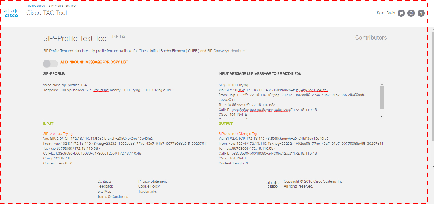
Figure 8-10 The SIP-Profile Test Tool
References
“Cisco Unified Border Element Configuration Guide,” https://www.cisco.com/c/en/us/td/docs/ios-xml/ios/voice/cube/configuration/cube-book.html
“Configurable Pass-through of SIP INVITE Parameters,” https://www.cisco.com/en/US/docs/ios-xml/ios/voice/cube_sip/configuration/15-0m/voi-conf-pass-thro.html
“Dial Peer Configuration Guide,” https://www.cisco.com/c/en/us/td/docs/ios-xml/ios/voice/dialpeer/configuration/15-mt/vd-15-mt-book/vd-dp-overview.html
“In Depth Explanation of Cisco IOS and IOS-XE Call Routing,” https://www.cisco.com/c/en/us/support/docs/voice/ip-telephony-voice-over-ip-voip/211306-In-Depth-Explanation-of-Cisco-IOS-and-IO.html
Inamdar, Kaustubh, Steve Holl, Gonzalo Salgueiro, Kyzer Davis, and Chidambaram Arunachalam. Understanding Session Border Controllers: Comprehensive Guide to Designing, Deploying, Troubleshooting, and Maintaining Cisco Unified Border Element (CUBE) Solutions. Hoboken: Cisco Press, 2018.
RFC 2782, “A DNS RR for specifying the location of services (DNS SRV),” https://tools.ietf.org/html/rfc2782
RFC 3261, “SIP: Session Initiation Protocol,” https://www.ietf.org/rfc/rfc3261.txt
Exam Preparation Tasks
As mentioned in the section “How to Use This Book” in the Introduction, you have a couple of choices for exam preparation: the exercises here, Chapter 11, “Final Preparation,” and the exam simulation questions in the Pearson Test Prep software online.
Review All Key Topics
Review the most important topics in the chapter, noted with the key topics icon in the outer margin of the page. Table 8-17 lists these key topics and the page number on which each is found.
![]()
Table 8-17 Key Topics for Chapter 8


Complete Tables and Lists from Memory
Print a copy of Appendix C, “Memory Tables” (found on the companion website), or at least the section for this chapter and complete the tables and lists from memory. Appendix D, “Memory Tables Answer Key” (also on the companion website), includes completed tables and lists to check your work.
Define Key Terms
Define the following key terms from this chapter and check your answers in the glossary: