Chapter 10. Unified CME and SRST
This chapter covers the following topics:
• Introduction to Unified CME and Unified SRST: This section provides an overview of Unified CME operation and Unified SRST operation with Unified CM for remote site redundancy.
• Unified CME Initial Configuration: This section discusses the items required to perform the initial configuration and registration of SIP IP phones with a Unified CME system, including manual and auto-registration of IP phones.
• Unified CME Dial Design: This section covers the main items required to understand and deploy a Unified CME dial plan, including Unified CME virtual dial peers and a refresher on IOS call routing for SIP trunks with Unified CME.
• Unified CME Call Coverage Features: This section details how to implement Unified CME features such as voice hunt groups, multicast paging, and call park.
• Survivable Remote Site Telephony (Unified SRST): The chapter ends with an overview of Unified SRST, along with the applicable configurations and items required to verify that the feature is working as expected.
This chapter covers the following CLACCM 300-815 exam topics:
• 2.1 Configure Cisco Unified Communications Manager Express for SIP phone registration
• 2.2 Configure Cisco Unified CME dial plans
• 2.3 Implement toll fraud prevention
• 2.4 Configure these advanced Cisco Unified CME features
• 2.4.a Hunt groups
• 2.4.b Call park
• 2.4.c Paging
• 2.5 Configure SIP SRST gateway
When deploying Unified Communications Manager (Unified CM) in an enterprise, there are various types of sites or locations, with varying sizes and user requirements. One of the most common types of locations is the enterprise remote branch office. Cisco Unified Communications Manager Express (Unified CME) provides call processing to Cisco IP phones for distributed enterprise branch office environments and retail deployments. Even branch offices within the same enterprise can have different communication needs and requirements. Unified CME meets this need by providing local call control, mobility, and conferencing alongside data applications on Cisco Integrated Services Router (ISR) devices.
As an enterprise extends its IP telephony deployments from central sites to remote branch offices and teleworkers, a critical factor in achieving a successful deployment is the capability to support backup call control at these remote locations. Cisco Unified Survivable Remote Site Telephony (Unified SRST) and Cisco Unified Enhanced Survivable Remote Site Telephony (Unified E-SRST) provide solutions for supporting redundant call control in remote branch offices and the homes of teleworkers for Unified CM registered endpoints.
This chapter covers topics related to Unified CME and Unified SRST configuration, implementation, and troubleshooting that are important to the CCNP CLACCM 300-815 exam. It discusses the initial configuration of SIP IP phones that register with Unified CME, provides a refresher on IOS call routing as it pertains to Unified CME (including Unified CME toll fraud prevention features), and examines a select few supplementary call features used by these IP phones. The chapter closes with an overview of Unified SRST and the configuration required for and the IOS Unified SRST gateway. This chapter includes relevant configuration snippets and debugging output to illustrate the topics covered.
“Do I Know This Already?” Quiz
The “Do I Know This Already?” quiz allows you to assess whether you should read the entire chapter. If you miss no more than one of these self-assessment questions, you might want to move ahead to the “Exam Preparation Tasks” section of the chapter. Table 10-1 lists the major headings in this chapter and the “Do I Know This Already?” quiz questions related to the material in each of those sections to help you assess your knowledge of these specific areas. The answers to the “Do I Know This Already?” quiz appear in Appendix A, “Answers to the ‘Do I Know This Already?’ Quiz Questions.”
Table 10-1 “Do I Know This Already?” Foundation Topics Section-to-Question Mapping

1. Which Cisco product provides backup call agent redundancy to remote branch IP phones in the event of a WAN failure?
a. Unified CM
b. Unified CME
c. Unified SRST
d. Cisco Unified Border Element
2. Which configuration commands are required for registering SIP IP phones with Unified CME? (Choose three.)
a. max-dn
b. max-ephone
c. max-pool
d. source-address
e. ip source-address
3. For each of the following descriptions, provide the appropriate IOS command.
4. When utilizing SIP IP phone auto registration with Unified CME, what is the first file provided by Unified CME to the IP phone with the MAC address AAAA.BBBB.CCCC via TFTP?
a. CTLAAAABBBBCCCC.tlv
b. ITLAAAABBBBCCCC.tlv
c. ITLFile.tlv
d. SEPAAAABBBBCCCC.cnf.xml
e. XMLDefault.cnf.xml
5. Which show command can be used to view information about Unified CME virtual dial peers created for SIP IP phones?
a. show running-config
b. show voice register global
c. show voice register dn
d. show voice register pool
6. Which command is required before registered SIP IP phones can call other SIP IP phones or endpoints behind a SIP trunk?
a. ip address trusted list
b. allow-connections sip to sip
c. registrar server
d. telephony-service
7. When implementing voice hunt groups with Unified CME, which operational mode starts ringing all hunt group members at the same time?
a. Sequential
b. Peer
c. Longest idle
d. Parallel
8. Which SIP message is used to instruct SIP IP phones to join a specific multicast paging IP address and port in order to receive an inbound page?
a. INVITE
b. NOTIFY
c. REFER
d. UPDATE
9. Which actions are performed to park a call in a basic call park slot and then pick up that call? (Choose two.)
a. Click the Transfer softkey and transfer the call to the call park extension.
b. Click the Park softkey and let the system select a park slot.
c. Dial the applicable feature access code (FAC) along with the call park extension to retrieve the parked call.
d. Dial only the call park extension to retrieve the parked call.
10. Which of the following supplementary features does Unified Enhanced SRST (E-SRST) provide? (Choose two.)
a. Shared-line support
b. Voice hunt groups
c. Voicemail
d. LDAP directory services
11. When configuring Unified SRST parameters on Unified CM, which enterprise parameter is used to define how long an IP phone remains registered with the Unified SRST gateway before re-attempting communication with the Unified CM cluster?
a. Maximum Hold Duration Timer
b. Connection Monitor Duration
c. Hold Reversion Duration
d. Gateway Poll Timer
12. Which voice register global commands are required when configuring Unified SRST on an IOS gateway? (Choose two.)
a. max-ephone
b. max-pool
c. max-dn
d. mode cme
e. source-address
Foundation Topics
Introduction to Unified CME and Unified SRST
Many enterprises have remote branches that interface with the enterprise over a wide area network (WAN) connection. With this deployment option, Cisco Unified Communication Manager (Unified CM) endpoints may register with a remote Unified CM server over the WAN connection, as shown in Figure 10-1.
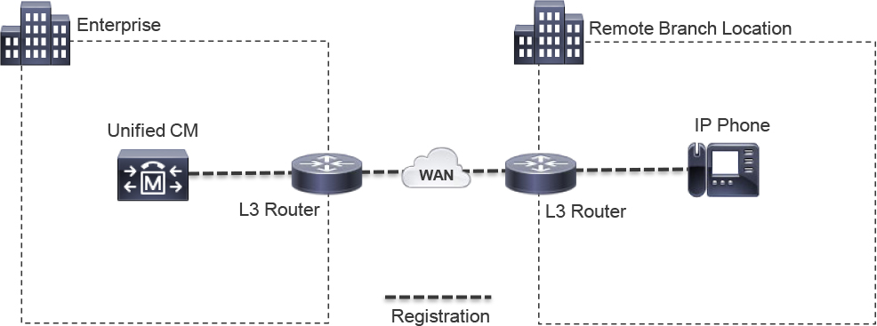
Figure 10-1 Remote Phone Registering to the Enterprise over the WAN
Depending on the size of the remote branch, there may be alternative deployment options that limit WAN utilization and dependency. For example, these locations may already have a Cisco IOS gateway performing routing, security, or other function, and the same Cisco ISR device can be leveraged to run Unified CME to provide local call agent and PSTN interoperability. In this scenario, the remote IP phones only use the WAN connection when calling endpoints on the enterprise, as shown in Figure 10-2.
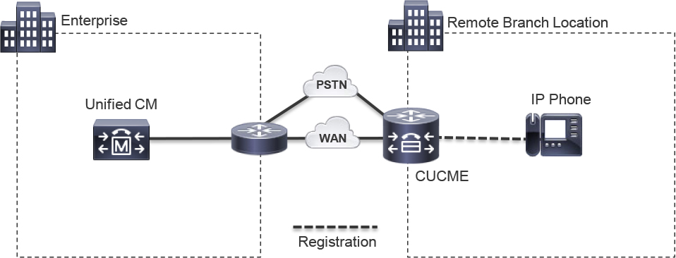
Figure 10-2 Remote Unified CME with Optional WAN Connection to the Enterprise
If a WAN and Unified CM deployment option is implemented, the local IOS gateway can still offer Unified SRST functionality. With Unified SRST, the local ISR acts as a backup call agent, and in the event of WAN outage, remote branch IP phones can register to the IOS Unified SRST gateway and continue with limited functionality, thus enabling continued business operation and customer satisfaction. Figure 10-3 illustrates the same deployment as Figure 10-2 except that the IP phone registers to Unified CM, with the Unified SRST gateway acting as a backup call agent in the event of an unexpected outage.
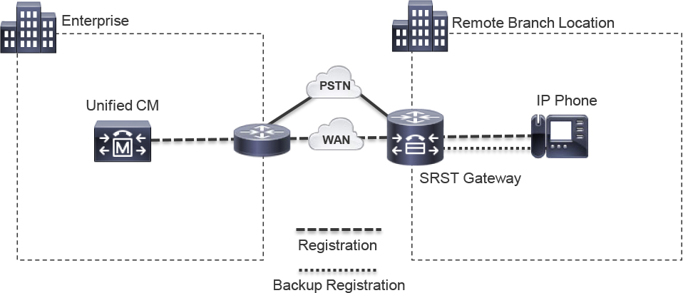
Figure 10-3 Remote Phone Registering to Enterprise with Backup Unified SRST Gateway
Unified CME Initial Configuration
Unified CME operates in IOS or IOS XE voice gateways on the ISR series of hardware routers or the Cloud Service Router (CSR) virtual machine. As a result, the Unified CME version is directly tied to the IOS version running on the platform. A single Unified CME system can register a finite number of SIP or SCCP IP phones, with the limiting factor being the hardware platform. For example, the largest ISR device that can run Unified CME at this writing is the ISR 4461, which can register 450 IP phones and manage 1200 directory numbers (DNs). You can configure Unified CME to provide many supplementary call features, including voice hunt groups, call park, paging, ad hoc conferencing, Music on Hold, Single Number Reach, Extension Mobility, and call queuing. Unified CME also provides access for enterprise IP phones to connect with public networks and external parties by way of traditional analog, digital, and IP connections; this chapter focuses on SIP trunks. As you read, you might notice that many of the dial plan and call routing commands used with Unified CME are like those used with CUBE, as described in earlier Chapter 8, “CUBE Call Routing and Digit Manipulation.”
Before starting a fresh Unified CME configuration, you should check the IOS–to–Unified CME compatibility matrix to verify the Unified CME version running on a given IOS version. For example, IOS XE Version 16.12.1a runs Unified CME Version 12.6. The given Unified CME version dictates the supported IP phone models and even the minimum supported firmware version that should be running on a given endpoint. Knowing this information before starting a deployment is crucial to avoiding issues with version and hardware incompatibility that might result in an IP phone not registering to Unified CME and losing valuable time during the implementation phase of a project. Be sure to consult the Unified CME roadmap to verify when specific features have been implemented to ensure that the right version has been selected to meet your business needs.
Note
Unified CME with the CSR platform supports only SIP IP phones and has a different feature set than the Unified CME counterpart that runs on ISR hardware. Refer to the official Virtual Unified CME documentation for more information about CSR features.
The Unified CM IOS Matrix can be found here:
https://www.cisco.com/c/en/us/td/docs/voice_ip_comm/cucme/requirements/guide/33matrix.html
The Unified CME Roadmap can be found here:
Virtual CME guide can be found here:
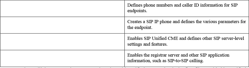
When you perform the initial configuration of SIP Unified CME, you need to complete a sequence of action items to enable the successful handling of SIP REGISTER requests from IP phones and, ultimately, successful registration of SIP IP phones:
![]()
• Global SIP application configuration: Global SIP parameters for registration and SIP-to-SIP calling should be enabled in the voice service voip configuration section. The registrar server command is required to allow a SIP application to process SIP REGISTER requests; without it, incoming SIP REGISTER requests from IP phones will be rejected with a “SIP/2.0 503 Service Unavailable - registrar unavail or not enabled” error. In addition, the allow-connections sip to sip command is required to allow SIP IP phones to call other SIP IP phones and place or receive calls from a service provider SIP trunk. Omitting this command results in a “404 Not Found” SIP error with Q.850 cause code 3 (indicating incompatible protocols) when attempting a SIP-to-SIP call.
With older versions of Unified CME, the IP address range of the IP phones should be defined in the ip address trusted list section under voice service voip to prevent the IOS toll fraud prevention feature from silently discarding (that is, dropping) the SIP REGISTER packet that is received from an untrusted source. With newer Unified CME versions (12.6 and later), the dynamic IP trusted list feature creates an entry in the IP trusted list based on the SIP Contact header observed during a successful SIP registration. When an IP phone unregisters, the entry in the trusted list is removed. Example 10-1 shows the static configuration required for older Unified CMEs, which involves defining the IP phone subnet 14.50.214.0 /24 as trusted. Later sections of this chapter highlight the dynamic IP trusted list feature in debugging examples and show command output to cover both scenarios.
• Global SIP CME configuration: SIP Unified CME should be enabled by using the mode cme voice register global command and defining a source address for SIP Unified CME traffic. In addition, the total number of IP phones and DNs needs to be configured by using max-pool and max-dn, respectively. The IP address defined by the source-address command should be a valid IP address of an interface that is up and active on the local router.
Example 10-1 Unified CME Initial Configuration Steps
! Step 1
voice service voip
 ip address trusted list
  ipv4 14.50.214.0 255.255.255.0
 allow-connections sip to sip
 sip
  registrar server
!
! Step 2
voice register global
 mode cme
 source-address 172.18.110.42
 max-pool 50
 max-dn 200
To confirm any custom or default configurations with SIP Unified CME, you can issue the command show voice register global. This command is also useful for finding the version of SIP Unified CME that is running on a device if the IOS–to–Unified CME compatibility matrix is not handy. Example 10-2 shows a truncated sample of output from this command. This command can also be used to view active registration statistics and other useful information about IP phones.
Example 10-2 Verification of Unified CME Global Configuration Parameters
rtp-cube# show voice register global
CONFIG [Version=12.6]
========================
  Version 12.6
  Mode is cme
  Max-pool is 50
  Max-dn is 200
[..truncated for brevity..]
Source-address is 172.18.110.42 port 5060
[..truncated for brevity..]
  Tftp path is system:/cme/sipphone
  Generate text file is disabled
  Tftp files are not created
[..truncated for brevity..]
Active registrations : 0
Total SIP phones registered: 0
With the global configuration complete, the Unified CME is ready to start registering SIP IP phones. One of two methods for registering phones can be leveraged, based on preference:
• Manual registration: This registration method involves creating one or many voice register dn entries for the directory numbers along with a unique voice register pool for each IP phone. This pool is also used to define other phone-level settings for each individual phone that will register with Unified CME. The DN and pool association must be done manually by a Unified CM administrator. With manual registration, the provisioning for each phone can be greatly customized before the phone registers.
• Auto-registration: This registration method involves defining a list of DNs to hand out to endpoints attempting to initiate SIP registration with Unified CME. The use of the voice register dn and voice register pool commands is automated by Unified CME, and the association of the two commands is also automatic. Once a phone is registered, you can create a tailored configuration by modifying the configuration settings created automatically by the system.
The following sections cover these two registration methods.
SIP Phone Manual Registration
To manually register a SIP IP phone, you need to configure a few key configuration sections. The process involves the following steps:
![]()
Step 1. Define a voice register dn with an extension. You can also define optional values, such as caller ID, phone display, and call forwarding settings, where needed. In addition, you can add shared line and max call information, although it is not required. You need to define a single unique voice register dn for each unique extension required.
Step 2. Create a voice register pool that references the MAC address of the endpoint requiring registration. The model of the endpoint registering using this pool and a mapping of the extension to a button on the phone’s display are also required for proper registration. A username and password should be configured to facilitate ad hoc authentication checks with CME during registration. Finally, you can modify optional parameters on the pool, such as the audio codec, DTMF relay, Layer 4 transport protocol, and phone display.
Step 3. Instruct Unified CME to generate a configuration file for the endpoint. Create the configuration file by issuing the create profile command under voice register global. This will create phone configurations files which take the name of SEP<mac-address>.cnf.xml. Without this step, Unified CME does not provide the configuration file requested by the IP phone during the TFTP phase of the phone boot process. Any time a voice register Unified CME command is modified, removed, or added to the system, you must re-issue the create profile command to instruct Unified CME to regenerate the TFTP configuration files from scratch. If you do not perform this step after a modification is made to the voice register configuration, the cnf.xml file becomes out of sync with the Unified CME voice register configuration, and the modification is not properly made on the IP phone.
Example 10-3 shows the configuration for three different voice register dn entries. The first entry defines the extension number 7777, and the name command defines the caller ID entry KYDAVIS-7777. The caller ID information is used in SIP messaging when establishing calls with other endpoints and remote parties. The label command controls the text for a given line on the display of the IP phone. The second voice register DN entry consists of the same commands, but this DN will be used as the primary extension of a second IP phone.
The last voice register dn entry defines the number 9999 and establishes call forwarding settings for busy and no answer (noan). These settings indicate that during a busy condition (that is, when the max number of calls have been surpassed), the attempted call forwards to 8888 rather than attempting to ring the 9999 extension. The timeout factor on the no answer call-forward setting is in seconds, and Example 10-3 indicates that after three 6-second ring cycles, the call is forwarded from extension 9999 to extension 8888. The caller ID name and line appearance label are defined in the same way as the previous two DNs. Finally, the DN is set to a shared line with a maximum number of concurrent calls set to maximum value of 16. The shared line functionality enables you to apply this voice register dn as a line appearance on more than one IP phone; this is illustrated in upcoming examples.
Example 10-3 Sample Configuration for Two Primary Extensions and One Shared Line Extension
!
voice register dn  1
 number 7777
 name KYDAVIS-7777
 label SIP-7777
!
voice register dn  2
 number 8888
 name PKINANE-8888
 label SIP-8888
!
voice register dn  3
 number 9999
 call-forward b2bua busy 8888
 call-forward b2bua noan 8888 timeout 18
 name SIP-SHARED
 label SIP-SHARED-9999
 shared-line max-calls 16
!
Example 10-4 shows two voice register pool entries configured. The first entry is for extension 8865, with a MAC address ending in A017, as defined by the id mac and type commands.
Note
You must use the id mac command before using the type command, or you will get the error “Please configure voice-register-pool id first.”
Next, the phone lines are associated with the voice register dn commands used earlier. The syntax of this association is as follows:
number line-appearance-number dn voice-register-dn-tag
In Example 10-4, you can see that the first phone defined for the pool has associated line appearance 1 (number 1) with voice register dn 1; in addition, it has line appearance 2 (number 2) with voice register dn 3, the shared line created previously. Likewise, phone 2 has associated line appearance 1 (number 1) with voice register dn 2 and line appearance 2 (number 2) with the shared line voice register dn 3.
Next, a username and password are defined on the phone. The IP phone uses the username and password in two different ways:
• The password defined on the pool is requested when attempting to enter the Admin Settings menu for the IP phone.
• The username and password are provided to answer ad hoc registration challenges in Unified CME when the IP phone sending a SIP REGISTER does not reside on the same subnet as the Unified CME voice register global source address. Even when the IP phones and Unified CME reside on the same subnet, the act of defining individual usernames and passwords should be completed as a best practice.
With the MAC address, phone type, and number association complete, optional parameters can be configured. In Example 10-4, you can see a description defined; this description influences the value displayed in the top left of the IP phone’s display, and the codec command changes the audio codec from the default of g728r8 to g711ulaw. If you want to define more than one codec, you can use voice-class codec instead of codec. (Refer to Chapter 9, “CUBE Interworking Features,” for more information on voice class codecs.) IP phones registered to SIP Unified CME default to UDP as the transport protocol type rather than TCP for registration. You can use the command session-transport tcp on a voice register pool to enable TCP transport and change the default value. Finally, you can define the dual-tone multifrequency (DTMF) relay mechanisms by using the dtmf-relay command.
![]()
Example 10-4 Sample Configuration for Two SIP IP Phones
!
voice register pool  1
 id mac C4B3.6ABA.A017
 type 8865
 number 1 dn 1
 number 2 dn 3
 username phone-one password C1sc0Vo1p
 description PHONE ONE
 codec g711ulaw
!
voice register pool  2
 id mac D0EC.35FF.6503
 type 8865
 number 1 dn 2
 number 2 dn 3
 username phone-two password C1sc0Vo1p
 description PHONE TWO
 codec g711ulaw
 session-transport tcp
 dtmf-relay rtp-nte
!
With the voice register DN commands and voice register pool commands configured, you need to instruct Unified CME to create the configuration XML files that the IP phone will request. Example 10-5 shows this process and also the verification of the configuration file generation. The output of the show voice register global command indicates whether TFTP files have been created and the locations of the system-generated files. You can further verify the TFTP configuration files by issuing the show voice register tftp-bind command, which details the location and alias of the TFTP files on the system.
Example 10-5 Creating and Verifying Configuration Files for SIP IP Phones
rtp-cme# conf t
rtp-cme (config)# voice register global
rtp-cme (config-register-global)# create profile

rtp-cme# show voice register global | include Tftp
  Tftp path is system:/cme/sipphone
  Tftp files are created, current syncinfo 1300381319824539

rtp-cme# show voice register tftp-bind
tftp-server url system:/cme/sipphone/syncinfo.xml alias syncinfo.xml
tftp-server url system:/cme/sipphone/SIPDefault.cnf alias SIPDefault.cnf
tftp-server url system:/cme/sipphone/softkeyDefault_kpml.xml alias softkeyDefault_kpml.xml
tftp-server url system:/cme/sipphone/softkeyDefault.xml alias softkeyDefault.xml
tftp-server url system:/cme/sipphone/skPublicConf_kpml.xml alias skPublicConf_kpml.xml
tftp-server url system:/cme/sipphone/skPublicConf.xml alias skPublicConf.xml
tftp-server url system:/cme/sipphone/skPersonalConf_kpml.xml alias skPersonalConf_kpml.xml
tftp-server url system:/cme/sipphone/skPersonalConf.xml alias skPersonalConf.xml
tftp-server url system:/cme/sipphone/featurePolicyDefault.xml alias featurePolicyDefault.xml
tftp-server url system:/cme/sipphone/SEPC4B36ABAA017.cnf.xml alias SEPC4B36ABAA017.cnf.xml
tftp-server url system:/cme/sipphone/SEPD0EC35FF6503.cnf.xml alias SEPD0EC35FF6503.cnf.xml
You can view the contents of a file by entering the more command in conjunction with the absolute path of the file, as shown in Example 10-6. The output in this example has been trimmed down greatly to illustrate the items configured earlier and show how the IOS commands translate to the XML configuration file that will be downloaded by the IP phone. Compare and contrast the output in Example 10-6 with the output in Example 10-1, Example 10-3, and Example 10-4 to get a better idea of exactly which items the IOS commands change.
Example 10-6 Verifying the Content of a SIP IP Phone Configuration File
rtp-cme# more system:/cme/sipphone/SEPC4B36ABAA017.cnf.xml
<sipPort>5060</sipPort>
<processNodeName>172.18.110.42</processNodeName>

<line button="1” lineIndex="1">
<featureLabel>SIP-7777</featureLabel>
<name>7777</name>
<displayName>KYDAVIS-7777</displayName>
<authName>phone-one</authName>
<authPassword>C1sc0Vo1p</authPassword>
<sharedLine>false</sharedLine>

<line button="2” lineIndex="2">
<featureLabel>SIP-SHARED-9999</featureLabel>
<name>9999</name>
<displayName>SIP-SHARED</displayName>
<authName>phone-one</authName>
<authPassword>C1sc0Vo1p</authPassword>
<sharedLine>true</sharedLine>

<preferredCodec>g711ulaw</preferredCodec>
<phoneLabel>PHONE ONE</phoneLabel>
<phonePassword>C1sc0Vo1p</phonePassword>
<versionStamp>1300381319824539</versionStamp>
In Unified CME Version 12.6 and above, the password for the IP phone username command should be a value between 6 and 15 alphanumeric characters; the password should include no special characters but should have at least one uppercase letter, one lowercase letter, and one numeric character. A password that does not meet these guidelines, such as cisco (as shown in Example 10-7), fails to be accepted, and IOS issues a guidance message about the proper password format.
Example 10-7 IP Phone Password Restrictions
rtp-cme(config-register-pool)# username cisco password cisco
Error: The password you have entered is invalid.
Your password must contain:
1. A minimum of 6 and a maximum of 15 alphanumeric characters,
   excluding symbols and special characters.
2. A minimum of one numeral, one uppercase alphabet, and one
   lowercase alphabet.
In the versions of IOS XE greater than 16.11, the password for voice features should be encrypted with AES and a master secret. You configure this by using the commands shown in Example 10-8. This command set will applies an extra level of password encryption to running configuration SIP password commands in the sip-ua, voice register global, and voice register pool configuration sections.
Example 10-8 Cisco Recommended AES Master-Key Configuration Password Encryption
!
password encryption aes
key config-key password-encrypt CISCO123
!
Tip
Before downgrading a Unified CME or CUBE deployment with password encryption, you should issue the command no password encryption; otherwise, older IOS-XE versions will be unable to decrypt the password in the running configuration.
Unified CME IP Phone Registration Overview
With the global configurations in place via voice service voip and voice register global along with the applicable configurations for each extension and IP phone defined by the respective voice register dn and voice register pool, you should be ready to register the endpoint. The following sequence of events occur with a phone registering to Unified CME:
![]()
Step 1. The IP phone requests the TFTP configuration file from Unified CME. This IP phone will be provided a TFTP server by way of Option 150, Option 66, or manual Alternate TFTP configuration via the phone settings. The TFTP file contains username/password, line information, and the call agent where registration should be attempted. (Review Example 10-6 for more information on the contents of the CNF.XML TFTP file.)
Step 2. The IP phone generates a SIP REGISTER message to Unified CME, based on the call agent information in the configuration file it received from Unified CME via TFTP.
Step 3. Unified CME performs trusted list verification to ensure that the IP phone’s IP address falls within an IP subnet that is permitted to be processed by the SIP application. If the IP phone’s subnet passes this check, the SIP REGISTER message is processed.
Step 4. If Unified CME and the IP phone are in different subnets, Unified CME challenges the IP phone for authentication by sending a SIP “401 Unauthorized” response that includes a SIP WWW-Authenticate header.
Step 5. The IP phone leverages the username/password from the TFTP configuration file received in step 1 to generate a new SIP REGISTER message and embed this credential information into the SIP Authorization header.
Step 6. Unified CME verifies that the information provided in the second SIP REGISTER message is valid. If the check passes, the registration is successful, and a SIP “200 OK” response is sent to the IP phone.
Step 7. The IP phone is now registered and performs periodic registration renewals to confirm registration.
When troubleshooting SIP Unified CME registration issues, the following debug commands can be very beneficial in understanding the steps just listed:
!
debug tftp events
!
debug voip iptrust
debug voip iptrust detail
!
debug ip tcp transaction
!
debug ccsip messages
debug ccsip error
!
debug voice register event
debug voice register error
debug voice register session
!
Example 10-9 illustrates the configuration steps just presented and these debug commands.
Example 10-9 Good Registration Based on the Previous Examples and Debug Commands
! Step 1, TFTP CNF.XML Download
Nov 16 18:25:02.717 EST: TFTP: Looking for SEPC4B36ABAA017.cnf.xml
Nov 16 18:25:02.717 EST: TFTP: Opened system:/cme/sipphone/SEPC4B36ABAA017.cnf.xml, fd 10, size 5802 for process 689
Nov 16 18:25:02.728 EST: TFTP: Finished system:/cme/sipphone/SEPC4B36ABAA017.cnf.xml, time 00:00:00 for process 689
! Step 2, REGISTER from IP Phone to Unified CME
Nov 16 18:25:09.729 EST: //-1/xxxxxxxxxxxx/SIP/Msg/ccsipDisplayMsg:
Received:
REGISTER sip:172.18.110.42 SIP/2.0
Via: SIP/2.0/UDP 14.50.214.117:5060;branch=z9hG4bK78414cf8
From: <sip:[email protected]>;tag=c4b36abaa01700040961ab81-46269f04
To: <sip:[email protected]>
Call-ID: [email protected]
Max-Forwards: 70
Session-ID: ff6075ea00105000a000c4b36abaa017;remote=00000000000000000000000000000000
CSeq: 101 REGISTER
User-Agent: Cisco-CP8865/12.5.1
Contact: <sip:[email protected]:5060;transport=udp>;+sip.instance="<urn:uuid:00000000-0000-0000-0000-c4b36abaa017>";+u.sip!devicename.ccm.cisco.com="SEPC4B36ABAA017";+u.sip!model.ccm.cisco.com="36225"
Content-Length: 0
Reason: SIP;cause=200;text="cisco-alarm:25 Name=SEPC4B36ABAA017 ActiveLoad=sip8845_65.12-5-1SR3-74.loads InactiveLoad=sip8845_65.12-1-1-12.loads Last=initialized"
Expires: 3600
! Step 3, Trusted List Check
Nov 16 18:25:09.722 EST: iptrust_silent_discard_authenticate
Nov 16 18:25:09.722 EST: iptrust_authenticateDynamicList: successfully authenticated
Nov 16 18:25:09.722 EST: iptrust_silent_discard_authenticate: ip[14.50.214.117] authenticate is passed by dynamic ip addr
! Step 4, Register processed and auth check + 401 Unauthorized
Nov 16 18:25:09.731 EST: VOICE_REG_POOL: Register request for (7777) from (14.50.214.117)
Nov 16 18:25:09.731 EST: auth absent
Nov 16 18:25:09.731 EST: VOICE_REG_POOL: Contact doesn't match any pools
Nov 16 18:25:09.731 EST: //53/2A615A7B806E/SIP/Error/ccsip_spi_register_incoming_registration:
 Registration Authorization failed with authorization header=

Nov 16 18:25:09.732 EST: //53/2A615A7B806E/SIP/Msg/ccsipDisplayMsg:
Sent:
SIP/2.0 401 Unauthorized
Via: SIP/2.0/UDP 14.50.214.117:5060;branch=z9hG4bK78414cf8
From: <sip:[email protected]>;tag=c4b36abaa01700040961ab81-46269f04
To: <sip:[email protected]>;tag=BEB7362B-1B18
Call-ID: [email protected]
Server: Cisco-SIPGateway/IOS-16.12.1a
CSeq: 101 REGISTER
WWW-Authenticate: Digest realm="",nonce="032AD1371312218B",algorithm=MD5,qop="auth"
Content-Length: 0
! Step 5, New Register with Authorization header
Nov 16 18:25:09.745 EST: //-1/xxxxxxxxxxxx/SIP/Msg/ccsipDisplayMsg:
Received:
REGISTER sip:172.18.110.42 SIP/2.0
Via: SIP/2.0/UDP 14.50.214.117:5060;branch=z9hG4bK7ffb6b72
From: <sip:[email protected]>;tag=c4b36abaa01700040961ab81-46269f04
To: <sip:[email protected]>
Call-ID: [email protected]
Max-Forwards: 70
Session-ID: ff6075ea00105000a000c4b36abaa017;remote=00000000000000000000000000000000
CSeq: 102 REGISTER
User-Agent: Cisco-CP8865/12.5.1
Contact: <sip:[email protected]:5060;transport=udp>;+sip.instance="<urn:uuid:00000000-0000-0000-0000-c4b36abaa017>";+u.sip!devicename.ccm.cisco.com="SEPC4B36ABAA017";+u.sip!model.ccm.cisco.com="36225"
Authorization: Digest username="phone-one",realm="",uri="sip:172.18.110.42",response="df9e6b9321586852e0a296fb362e73fa",nonce="032AD1371312218B",cnonce="7d87adc4",qop=auth,nc=00000001,algorithm=MD5
Content-Length: 0
Expires: 3600
! Step 6, Validate and Successful Registration
Nov 16 18:25:09.747 EST: VOICE_REG_POOL: Register request for (7777) from (14.50.214.117)
Nov 16 18:25:09.747 EST:  function :: voice_reg_validate_pool_credential: encrypt_mode is TRUE
Nov 16 18:25:09.748 EST: VOICE_REG_POOL: Registration successful for 7777, registration id is 11

Nov 16 18:25:09.751 EST: //53/2A615A7B806E/SIP/Msg/ccsipDisplayMsg:
Sent:
SIP/2.0 200 OK
Via: SIP/2.0/UDP 14.50.214.117:5060;branch=z9hG4bK7ffb6b72
From: <sip:[email protected]>;tag=c4b36abaa01700040961ab81-46269f04
To: <sip:[email protected]>;tag=BEB7362B-1B18
Call-ID: [email protected]
Server: Cisco-SIPGateway/IOS-16.12.1a
CSeq: 102 REGISTER
Supported: X-cisco-cme-sis-9.0.0
Supported: X-cisco-srtp-fallback
Contact: <sip:[email protected]:5060>;expires=3600;x-cisco-newreg
Expires:  3600
Content-Length: 0
In addition to debug commands, you can use multiple show commands to view the registration status of IP endpoints and gather useful information when troubleshooting Unified CME IP phone registration issues. The command show voice register global (shown in Example 10-10) details the total number of registered devices and some other statistics about registration. The show voice register pool all brief command provides an at-a-glance view of Unified CME IP phone registration. This command also shows the line appearances and DN mapping along with the pool number, MAC address, and IP information of the registered endpoint. Finally, you can use the show ip address trusted list command to view the trusted list information, including the dynamic trusted list discussed earlier.
Example 10-10 Verification Commands for SIP IP Phone Registration
rtp-cme# show voice register global
[..truncated for brevity..]
Total SIP phones registered: 2
  Total Registration Statistics
    Registration requests  : 12
    Registration success   : 12
    Registration failed    : 0
    unRegister requests    : 0
    unRegister success     : 0
    unRegister failed      : 0
    Auto-Register requests : 0
    Attempts to register
           after last unregister : 0
    Last register request time   : 18:25:09.754 EST Sat Nov 16 2019
    Last unregister request time :
    Register success time        : 18:25:09.755 EST Sat Nov 16 2019
    Unregister success time      :

rtp-cme# show voice register pool all brief
Pool ID              IP Address     Ln DN  Number  State
==== =============== ============== == === ======= ============
1 C4B3.6ABA.A017 14.50.214.117 1 1 7777$ REGISTERED
2 3 9999$ REGISTERED
2 D0EC.35FF.6503 14.50.214.118 1 2 8888$ REGISTERED
                                    2  3   9999$   REGISTERED

rtp-cme# show ip address trusted list
IP Address Trusted Authentication
 Administration State: UP
 Operation State:      UP

IP Address Trusted Call Block Cause: call-reject (21)

VoIP Dial-peer IPv4 and IPv6 Session Targets:
Peer Tag        Oper State      Session Target
--------        ----------      --------------

Configured IP Address Trusted List:
Dynamic IP Address Trusted List:
IP Address                                   Subnet Mask     Count Reason
-------------------------------------------- --------------- ----- ----------------
ipv4:14.50.214.117 2 Phone Registered
ipv4:14.50.214.118 2 Phone Registered
SIP Phone Auto-Registration
Consider the task of registering 450 IP phones, each with a unique DN. Using the steps shown in the previous section for two IP phones, you can see that while it is not an impossible task, it is very laborious and time-consuming. Furthermore, due to the number of required inputs, there is a very great chance for an input error. Simply mistyping a MAC address or another value could derail a deployment and lead to a lot of time spent troubleshooting the issue. Fortunately, Unified CME auto-registration exists to handle some of the configuration tasks for you and speed up initial Unified CME deployments.
Auto-registration begins the same way as manual registration: You configure voice service voip and voice register global the same way. However, then you use the auto-register configuration option under voice register global. First, you need to define the range of DNs that will be assigned on a first-come, first-served, round-robin basis. Next, you need to create a password for these phones. If needed, you can optionally define a template and tie it to the auto-register configuration by using the voice register template feature to provide even more default configurations to an auto-registered endpoint.
Example 10-11 shows the configuration for manual registration of phones and also the auto-registration configuration, which is highlighted in this example to stand out. You can see that AES password encryption with a master secret has been defined to ensure that the password for auto-registration is sufficiently encrypted in the running configuration. voice service voip is configured to enable the subnet for the IP phones, and SIP-to-SIP calling is enabled. The SIP registrar server command is enabled to allow the SIP application to process SIP REGISTER messages. The voice register global section is configured for mode cme, and the maximum number of pools (phones) and DNs (extension) are defined, along with the source address for Unified CME. Finally, the auto-registration configurations are enabled with service-enable, the password is enabled, and the first and last extension range is defined with the auto-assign command.
![]()
Example 10-11 SIP IP Phone Auto-Registration Configuration
!
password encryption aes
key config-key password-encrypt CISCO123
!
voice service voip
 ip address trusted list
  ipv4 14.50.214.0 255.255.255.0
 allow-connections sip to sip
 sip
  registrar server
!
voice register global
 mode cme
 source-address 172.18.110.62 port 5060
 max-dn 200
 max-pool 50
 auto-register
  service-enable
  password C1sc0Vo1p
  auto-assign 7000 to 7050
 create profile
!
With the global auto-registration configurations in place, you should be ready to register the endpoints. Phone auto-registration to Unified CME involves the following events, and Examples 10-12 through 10-19 show debug command output that goes with these steps:
![]()
Step 1. The IP phone requests the TFTP configuration file from Unified CME. This IP phone will be provided a TFTP server by way of Option 150, Option 66, or manual Alternate TFTP configuration on the phone. With auto-registration, the SEP<mac-address>cnf.xml file is not created because no pool or DN information exists yet. As a result, the IP phone downloads the XMLDefault.cnf.xml file provided by Unified CME’s TFTP service. This file contains enough information to keep the registration process moving along, such as the Unified CME IP address for accepting SIP REGISTER messages (see Example 10-12).
Example 10-12 Debug Snippet 1 for Good SIP IP Phone Auto-Registration
! Step 1, download XMLDefault.cnf.xml
018102: Nov 16 20:05:49.882 EST: TFTP: Looking for XMLDefault.cnf.xml
018103: Nov 16 20:05:49.883 EST: TFTP: Opened system:/its/vrf1/XMLDefault.cnf.xml, fd 10, size 3627 for process 696
018104: Nov 16 20:05:49.890 EST: TFTP: Finished system:/its/vrf1/XMLDefault.cnf.xml, time 00:00:00 for process 696
Step 2. The IP phone generates a SIP REGISTER message to Unified CME, based on the information in the configuration XMLDefault.cnf.xml file it received in the previous step (see Example 10-13).
Example 10-13 Debug Snippet 2 for Good SIP IP Phone Auto-Registration
! Step 2, Register sent from IP Phone to Unified CME
018132: Nov 16 20:05:51.485 EST: //-1/xxxxxxxxxxxx/SIP/Msg/ccsipDisplayMsg:
Received:
REGISTER sip:172.18.110.62 SIP/2.0
Via: SIP/2.0/UDP 14.50.214.118:5060;branch=z9hG4bK4ad22cd0
From: <sip:[email protected]>;tag=d0ec35ff6503005a17249b2d-5c77b5e9
To: <sip:[email protected]>
Call-ID: [email protected]
Max-Forwards: 70
Session-ID: ec61d2cf00105000a000d0ec35ff6503;remote=00000000000000000000000000000000
CSeq: 164 REGISTER
User-Agent: Cisco-CP8865/12.5.1
Contact: <sip:[email protected]:5060;transport=udp>;+sip.instance="<urn:uuid:00000000-0000-0000-0000-d0ec35ff6503>";+u.sip!devicename.ccm.cisco.com="SEPD0EC35FF6503";+u.sip!model.ccm.cisco.com="36225";video
Supported: replaces,join,sdp-anat,norefersub,resource-priority,extended-refer,X-cisco-callinfo,X-cisco-serviceuri,X-cisco-escapecodes,X-cisco-service-control,X-cisco-srtp-fallback,X-cisco-monrec,X-cisco-config,X-cisco-sis-7.0.0,X-cisco-xsi-8.5.1
Content-Length: 0
Reason: SIP;cause=200;text="cisco-alarm:25 Name=SEPD0EC35FF6503 ActiveLoad=sip8845_65.12-5-1SR3-74.loads InactiveLoad=sip8845_65.12-1-1-12.loads Last=initialized"
Expires: 3600
Step 3. Unified CME performs trusted list verification to ensure that the IP phone’s IP address falls within an IP subnet that is a source trusted by the SIP application (see Example 10-14).
Example 10-14 Debug Snippet 3 for Good SIP IP Phone Auto-Registration
! Step 3, Verify IP Trusted List
018127: Nov 16 20:05:51.476 EST: iptrust_silent_discard_authenticate
018128: Nov 16 20:05:51.476 EST: iptrust_silent_discard_authenticate: ip[14.50.214.118] authenticate is passed by config ip addr
Step 4. Unified CME begins the process of automatically creating a voice register dn and voice register pool for the phone, based on the MAC address information received in the SIP REGISTER message and the information provided by the administrator in the auto-register, voice register global command. In addition, Unified CME automatically creates a SEP<mac address>cnf.xml configuration file for the MAC address of the phone (see Example 10-15).
Example 10-15 Debug Snippet 4 for Good SIP IP Phone Auto-Registration
! Step 4, Create pool and dn
018133: Nov 16 20:05:51.486 EST: voice_reg_get_reg_expires_timer: no voice register pool found
018136: Nov 16 20:05:51.487 EST: VOICE_REG_POOL: Register request for (AUTO-REG) from (14.50.214.118)
018137: Nov 16 20:05:51.487 EST: VOICE_REG_POOL: Auto Registration request from Name:d0ec35ff6503 IP:14.50.214.118
018138: Nov 16 20:05:51.487 EST: VOICE_REG_POOL: Auto-register: available DN tag found: 2
018139: Nov 16 20:05:51.487 EST: VOICE_REG_POOL: Auto-register: available DN found: 7001
018140: Nov 16 20:05:51.487 EST: VOICE_REG_POOL: Auto-register: available pool tag found: 2
018155: Nov 16 20:05:51.495 EST: VOICE_REG_POOL: auto-register DN (2) and Pool (2), created for number (7001)
018156: Nov 16 20:05:51.495 EST: VOICE_REG_POOL: 2 out of 51 DN numbers in use
Step 5. Unified CME sends a 200 OK (see Example 10-16).
Example 10-16 Debug Snippet 5 for Good SIP IP Phone Auto-Registration
! Step 5, 200 OK to Register
018163: Nov 16 20:05:51.496 EST: //93/3B8C28998114/SIP/Msg/ccsipDisplayMsg:
Sent:
SIP/2.0 200 OK
Via: SIP/2.0/UDP 14.50.214.118:5060;branch=z9hG4bK4ad22cd0
From: <sip:[email protected]>;tag=d0ec35ff6503005a17249b2d-5c77b5e9
To: <sip:[email protected]>;tag=797A1512-E50
Call-ID: [email protected]
Server: Cisco-SIPGateway/IOS-16.12.1a
CSeq: 164 REGISTER
Supported: X-cisco-cme-sis-9.0.0
Supported: X-cisco-srtp-fallback
Contact: <sip:[email protected]:5060>;expires=3600;x-cisco-newreg
Expires:  3600
Content-Length: 0
Step 6. Unified CME sends an out-of-dialog (OOD) SIP NOTIFY message that includes action=restart in the SIP message body to instruct the IP phone to restart. The phone replies with a 200 OK message and restarts, as instructed (see Example 10-17).
Example 10-17 Debug Snippet 6 for Good SIP IP Phone Auto-Registration
! Step 6, Reset the IP Phone
018173: Nov 16 20:05:51.636 EST: VOICE_REG_POOL: Pool[2]: service-control (reset type: 1) message sent to sip:[email protected]
018176: Nov 16 20:05:51.638 EST: //0/000000000000/SIP/Msg/ccsipDisplayMsg:
Sent:
NOTIFY sip:[email protected]:5060;transport=udp SIP/2.0
Via: SIP/2.0/UDP 172.18.110.62:5060;branch=z9hG4bK492134
From: <sip:[email protected]>;tag=797A15A9-26CD
To: <sip:[email protected]>
Call-ID: [email protected]
CSeq: 101 NOTIFY
Max-Forwards: 70
User-Agent: Cisco-SIPGateway/IOS-16.12.1a
Event: service-control
Subscription-State: active
Contact: <sip:[email protected]:5060>
Content-Type: text/plain
Content-Length: 185

action=restart
RegisterCallId={[email protected]}
ConfigVersionStamp={2513463472421178}
DialplanVersionStamp={}
SoftkeyVersionStamp={2513463472421178}

018177: Nov 16 20:05:51.641 EST: //0/000000000000/SIP/Msg/ccsipDisplayMsg:
Received:
SIP/2.0 200 OK
Via: SIP/2.0/UDP 172.18.110.62:5060;branch=z9hG4bK492134
From: <sip:[email protected]>;tag=797A15A9-26CD
To: <sip:[email protected]>
Call-ID: [email protected]
Session-ID: ec61d2cf00105000a000d0ec35ff6503;remote=00000000000000000000000000000000
CSeq: 101 NOTIFY
Content-Length: 0
Step 7. Because the phone has performed a restart, as requested by Unified CME, the boot process starts again. This, in turn, means the phone re-requests the SEP<mac-address>cnf.xml file, just like in step 1. This file, which Unified CME created in step 4, is now provided to the IP phone by Unified CME’s TFTP service (see Example 10-18).
Example 10-18 Debug Snippet 7 for Good SIP IP Phone Auto-Registration
! Step 7, TFTP File Provided
018227: Nov 16 20:05:56.570 EST: TFTP: Looking for SEPD0EC35FF6503.cnf.xml
018228: Nov 16 20:05:56.570 EST: TFTP: Opened system:/cme/sipphone/SEPD0EC35FF6503.cnf.xml, fd 10, size 4841 for process 696
018229: Nov 16 20:05:56.579 EST: TFTP: Finished system:/cme/sipphone/SEPD0EC35FF6503.cnf.xml, time 00:00:00 for process 696
Step 8. The rest of the SIP registration process proceeds just like the manual registration process described earlier (refer to Example 10-9). However, note that the 401 Authentication request is not optional for auto-registered IP phones, and it always occurs (see Example 10-19).
Example 10-19 Debug Snippet 8 for Good SIP IP Phone Auto-Registration
! Step 8, Normal Registration
018274: Nov 16 20:06:03.690 EST: //-1/xxxxxxxxxxxx/SIP/Msg/ccsipDisplayMsg:
Received:
REGISTER sip:172.18.110.62 SIP/2.0
Via: SIP/2.0/UDP 14.50.214.118:5060;branch=z9hG4bK7439dbce
From: <sip:[email protected]>;tag=d0ec35ff6503005f542614bf-5f1dcbea
To: <sip:[email protected]>
Call-ID: [email protected]
Max-Forwards: 70
Session-ID: ec61d2cf00105000a000d0ec35ff6503;remote=00000000000000000000000000000000
CSeq: 166 REGISTER
User-Agent: Cisco-CP8865/12.5.1
Contact: <sip:[email protected]:5060;transport=udp>;+sip.instance="<urn:uuid:00000000-0000-0000-0000-d0ec35ff6503>";+u.sip!devicename.ccm.cisco.com="SEPD0EC35FF6503";+u.sip!model.ccm.cisco.com="36225"
Supported: replaces,join,sdp-anat,norefersub,resource-priority,extended-refer,X-cisco-callinfo,X-cisco-serviceuri,X-cisco-escapecodes,X-cisco-service-control,X-cisco-srtp-fallback,X-cisco-monrec,X-cisco-config,X-cisco-sis-7.0.0,X-cisco-xsi-8.5.1
Content-Length: 0
Reason: SIP;cause=200;text="cisco-alarm:23 Name=SEPD0EC35FF6503 ActiveLoad=sip8845_65.12-5-1SR3-74.loads InactiveLoad=sip8845_65.12-1-1-12.loads Last=reset-restart"
Expires: 3600

018277: Nov 16 20:06:03.692 EST: VOICE_REG_POOL: Register request for (7001) from (14.50.214.118)
018278: Nov 16 20:06:03.692 EST: VOICE_REG_POOL: Contact matches pool 2 number list 1
018279: Nov 16 20:06:03.692 EST: auth absent

018285: Nov 16 20:06:03.694 EST: //95/42D27E11811A/SIP/Msg/ccsipDisplayMsg:
Sent:
SIP/2.0 401 Unauthorized
Via: SIP/2.0/UDP 14.50.214.118:5060;branch=z9hG4bK7439dbce
From: <sip:[email protected]>;tag=d0ec35ff6503005f542614bf-5f1dcbea
To: <sip:[email protected]>;tag=797A44BF-191B
Call-ID: [email protected]
Server: Cisco-SIPGateway/IOS-16.12.1a
CSeq: 166 REGISTER
WWW-Authenticate: Digest realm="",nonce="E2BA9BDC25BF3BD7",algorithm=MD5,qop="auth"
Content-Length: 0

018286: Nov 16 20:06:03.699 EST: //-1/xxxxxxxxxxxx/SIP/Msg/ccsipDisplayMsg:
Received:
REGISTER sip:172.18.110.62 SIP/2.0
Via: SIP/2.0/UDP 14.50.214.118:5060;branch=z9hG4bK440ccd38
From: <sip:[email protected]>;tag=d0ec35ff6503005f542614bf-5f1dcbea
To: <sip:[email protected]>
Call-ID: [email protected]
Max-Forwards: 70
Session-ID: ec61d2cf00105000a000d0ec35ff6503;remote=00000000000000000000000000000000
CSeq: 167 REGISTER
User-Agent: Cisco-CP8865/12.5.1
Contact: <sip:[email protected]:5060;transport=udp>;+sip.instance="<urn:uuid:00000000-0000-0000-0000-d0ec35ff6503>";+u.sip!devicename.ccm.cisco.com="SEPD0EC35FF6503";+u.sip!model.ccm.cisco.com="36225"
Authorization: Digest username="auto2",realm="",uri="sip:172.18.110.62",response="cc90b13f84162334528efa91944805b9",nonce="E2BA9BDC25BF3BD7",cnonce="09f5f76e",qop=auth,nc=00000001,algorithm=MD5
Supported: replaces,join,sdp-anat,norefersub,resource-priority,extended-refer,X-cisco-callinfo,X-cisco-serviceuri,X-cisco-escapecodes,X-cisco-service-control,X-cisco-srtp-fallback,X-cisco-monrec,X-cisco-config,X-cisco-sis-7.0.0,X-cisco-xsi-8.5.1
Content-Length: 0
Reason: SIP;cause=200;text="cisco-alarm:23 Name=SEPD0EC35FF6503 ActiveLoad=sip8845_65.12-5-1SR3-74.loads InactiveLoad=sip8845_65.12-1-1-12.loads Last=reset-restart"
Expires: 3600

018289: Nov 16 20:06:03.701 EST: VOICE_REG_POOL: Register request for (7001) from (14.50.214.118)
018290: Nov 16 20:06:03.701 EST: VOICE_REG_POOL: Contact matches pool 2 number list 1
018291: Nov 16 20:06:03.701 EST:  function :: voice_reg_validate_pool_credential: encrypt_mode is                     TRUE
018292: Nov 16 20:06:03.701 EST:  function :: voice_reg_validate_pool_credential: encrypt_mode is                     TRUE
018293: Nov 16 20:06:03.701 EST: VOICE_REG_POOL: Contact matches pool 2 number list 1
018294: Nov 16 20:06:03.701 EST: VOICE_REG_POOL: No entry for (14.50.214.118) found in srst contact table
018295: Nov 16 20:06:03.701 EST: VOICE_REG_POOL: key(7001) contact(14.50.214.118:5060) add to contact table
018296: Nov 16 20:06:03.701 EST: VOICE_REG_POOL: No entry for (7001) found in contact table
018297: Nov 16 20:06:03.702 EST: voice_register_create_dialpeer: adding ip [14.50.214.118] to dynamic trust list
018298: Nov 16 20:06:03.702 EST: iptrust_addDynamicListEntry: Trying to add ip[14.50.214.118] is_configured_ip[0] in DynamicTrust list
018299: Nov 16 20:06:03.702 EST: iptrust_findDynamicListEntry: Trying to find ip[14.50.214.118] in Dynamic Trust list
018300: Nov 16 20:06:03.702 EST: iptrust_findDynamicListEntry: Entry NOT found in Dynamic Trust List
018301: Nov 16 20:06:03.702 EST: iptrust_addDynamicListEntry: successfully added

018310: Nov 16 20:06:03.703 EST: VOICE_REG_POOL: Registration successful for 7001, registration id is 2
018311: Nov 16 20:06:03.704 EST: VOICE REGISTER POOL-2 has registered. Name:SEPD0EC35FF6503  IP:14.50.214.118  DeviceType:Phone-8865

018312: Nov 16 20:06:03.704 EST: %SIPPHONE-6-REGISTER: VOICE REGISTER POOL-2 has registered. Name:SEPD0EC35FF6503  IP:14.50.214.118  DeviceType:Phone-8865


018320: Nov 16 20:06:03.706 EST: //95/42D27E11811A/SIP/Msg/ccsipDisplayMsg:
Sent:
SIP/2.0 200 OK
Via: SIP/2.0/UDP 14.50.214.118:5060;branch=z9hG4bK440ccd38
From: <sip:[email protected]>;tag=d0ec35ff6503005f542614bf-5f1dcbea
To: <sip:[email protected]>;tag=797A44BF-191B
Call-ID: [email protected]
Server: Cisco-SIPGateway/IOS-16.12.1a
CSeq: 167 REGISTER
Supported: X-cisco-cme-sis-9.0.0
Supported: X-cisco-srtp-fallback
Contact: <sip:[email protected]:5060>;expires=3600;x-cisco-newreg
Expires:  3600
Content-Length: 0
Tip
To view the OOD SIP NOTIFY message to reset the phone, you use debug ccsip non-call in addition to the debug commands mentioned earlier in this chapter.
You can use the same show commands as before to view the auto-registered information (see Example 10-20). Note the asterisk (*) beside the REGISTERED state in the show voice register pool all brief command output; this indicates that this phone’s pool information was created automatically during the auto-registration process.
Example 10-20 Verification of SIP Auto-Registered IP Phones
sj-cme# show voice register pool all brief
Pool ID              IP Address     Ln DN  Number               State
==== =============== ============== == === ==================== ============
1    C4B3.6ABA.A017  14.50.214.117  1  1   7000$                REGISTERED*
2    D0EC.35FF.6503  14.50.214.118  1  2   7001$                REGISTERED*
* Pool is created automatically with auto-registration
sj-cme# show voice register global
[..truncated for brevity..]
Active registrations : 2
  Total SIP phones registered: 2
  Total Registration Statistics
    Registration requests  : 6
Registration success : 2
    Registration failed    : 2
    unRegister requests    : 0
    unRegister success     : 0
    unRegister failed      : 0
Auto-Register requests : 2
sj-cme# show ip address trusted list
IP Address Trusted Authentication
 Administration State: UP
 Operation State:      UP

IP Address Trusted Call Block Cause: call-reject (21)

VoIP Dial-peer IPv4 and IPv6 Session Targets:
Peer TagOper StateSession Target
--------------------------------

Configured IP Address Trusted List:
ipv4 14.50.214.0 255.255.255.0
Dynamic IP Address Trusted List:
IP Address              Subnet Mask     Count Reason
----------------------- --------------- ----- ----------------
ipv4:14.50.214.117 1 Phone Registered
ipv4:14.50.214.118 1 Phone Registered
In the running configuration shown in Example 10-21, you can see the auto-generated voice register DN and pool. This configuration is persistent through reloads if you save the configuration issuing copy running-config startup-config or simply write memory. From here, you can manually apply custom configurations to the voice register dn and voice register pool sections. Remember to apply the changes to the phone by issuing the create profile command in voice register global configuration mode.
Example 10-21 IOS-Generated Auto-Register Configuration
!
voice register dn  1
 number 7000
 no-reg
!
voice register dn  2
 number 7001
 no-reg
!
voice register pool  1
 busy-trigger-per-button 2
 id mac C4B3.6ABA.A017
 type 8865
 number 1 dn 1
 dtmf-relay rtp-nte
 username auto1 password 6 EfYghCf[fYLNicME^BGIcXQHCNhX_AAAB
 description AUTO-REG
 codec g711ulaw
!
voice register pool  2
 busy-trigger-per-button 2
 id mac D0EC.35FF.6503
 type 8865
 number 1 dn 2
 dtmf-relay rtp-nte
 username auto2 password 6 EfYghCf[fYLNicME^BGIcXQHCNhX_AAAB
 description AUTO-REG
 codec g711ulaw
!
Unified CME Dial Design
With the IP phone registration complete, you can now start creating a dial plan for the system. Unified CME uses traditional basic telephone service and VoIP dial peers for routing calls to and from service providers and other third-party networks. This means the configuration commands used to establish SIP trunk call routing on Unified CME are the same as those used for CUBE (refer to Chapter 8). The main difference is that Unified CME automatically creates VoIP dial peers for each registered voice register dn and voice register pool combination. These automatic Unified CME virtual dial peers are used as the inbound dial peers for calls originating from the IP phone and as the outbound dial peers for calls from Unified CME destined to a given directory number.
Unified CME Virtual Dial Peers
Example 10-22 uses the IP phones registered manually earlier in this chapter to illustrate the dial peers generated by the system. The output of the command show dial-peer voice summary shows the virtual Unified CME dial peers created for the extensions defined earlier in the chapter. The IPv4 address used as the session target is the IPv4 address of the registered SIP IP phone. Notice that the directory number 9999 shows up with two dial peers. This is due to the use of the shared-line command (refer to Example 10-3) along with the association of this DN with multiple voice register pool commands.
![]()
Example 10-22 Verification of Unified CME Virtual Dial Peers
rtp-cme# show dial-peer voice summary
dial-peer hunt 0
             AD                             PRE PASS SESS-SER-GRP  OUT
TAG    TYPE  MIN  OPER PREFIX  DEST-PATTERN FER THRU SESS-TARGET    STAT PORT KEEPALIVE  VRF
40001  voip  up   up           8888$         0  syst ipv4:14.50.214.118:5                NA
40002  voip  up   up           9999$         0  syst ipv4:14.50.214.118:5                NA
40003  voip  up   up           7777$         0  syst ipv4:14.50.214.117:5                NA
40004  voip  up   up           9999$         0  syst ipv4:14.50.214.117:5                NA
Note that these dial peers do not show up in the running configuration. You need to issue the command show voice register pool with a particular pool tag to view the virtual dial peer configuration for the DNs associated with that pool. Example 10-23 shows a truncated version of this command and illustrates the configuration values and default configurations defined on voice register pool 1; it also includes the virtual dial peers created by Unified CME. These dial peer tag IDs match the show dial-peer voice summary output from Example 10-22. In addition to using show voice register pool, you can use the command show voice register dial-peers to examine all Unified CME virtual dial peers.
Example 10-23 Viewing Virtual Dial Peer Configuration
rtp-cme# show voice register pool 1
 Pool Tag 1
Config:
  Mac address is C4B3.6ABA.A017
  Type is 8865
  Number list 1 : DN 1
  Number list 2 : DN 3
  Description is PHONE ONE
  username phone-one password R^CHIaLfF[ShU]LTYFeDFIWUFfUDeH[[AAB
  registration Call ID is [email protected]
  contact IP address: 14.50.214.117 port 5060
Dialpeers created:
Dial-peers for Pool 1:
dial-peer voice 40003 voip
 destination-pattern 7777$
 session target ipv4:14.50.214.117:5060
 session protocol sipv2
 digit collect kpml
 codec  g711ulaw bytes 160
  after-hours-exempt   FALSE
dial-peer voice 40004 voip
 destination-pattern 9999$
 session target ipv4:14.50.214.117:5060
 session protocol sipv2
 digit collect kpml
 codec  g711ulaw bytes 160
  call-fwd-busy        8888
  call-fwd-noan-timeou 18
  call-fwd-noan        8888
  after-hours-exempt   FALSE
Example 10-24 shows show call active voice brief | include pid being issued to make a simple test call from extension 7777 to extension 8888. You can see that dial peers from Example 10-23 are used in this call. The inbound call leg (Answer) is bound to inbound dial peer 40003, which was confirmed to be associated to extension 7777 on voice register pool 1. The outbound call leg (Originate) is using outbound dial peer 40001, which is the dial peer for voice register pool 2 and extension 8888, as confirmed by Example 10-23. Remember that the allow-connections sip to sip command is required in voice service VoIP configuration; if it is not used, a call from one SIP IP phone to another fails with a “404 Not Found” SIP error with Q.850 cause code 3 (indicating incompatible protocols).
Example 10-24 A Call Between Two SIP IP Phones, Showing the Virtual Dial Peers
rtp-cme# show call active voice brief | include pid
<ID>:<CallID> <start>ms.<index>  +<connect> pid:<peer_id> <dir> <addr> <state>
1297 : 101 3270477390ms.1        +1850      pid:40003 Answer     7777  active
1297 : 102 3270477400ms.1        +1820      pid:40001 Originate  8888  active
When Unified CME receives a call for a shared line extension, such as the one configured in previous examples (9999), Unified CME attempts to send the call to all the IP phones simultaneously. If you issue show call active voice brief | include pid during the call setup, you see multiple outgoing dial peers for this call. The moment an IP phone answers the call, the other session establishment attempts are terminated with a SIP CANCEL message sent by Unified CME. If you reissue the command show call active voice brief | include pid after the call has connected, you now see one active outbound call and the dial peer of the endpoint that answered the call (see Example 10-25).
Example 10-25 A Call to a SIP Shared-Line Extension Detailing Two Outbound Virtual Dial Peers
rtp-cme# show call active voice brief | include pid
<ID>: <CallID> <start>ms.<index> (<start>) +<connect> pid:<peer_id> <dir> <addr> <state>
12A2 : 107 3273858320ms.1 () +-1 pid:2 Answer 1111 connecting
12A2 : 108 3273858340ms.1 () +-1 pid:40002 Originate 9999 connecting
12A8 : 109 3273858340ms.2 () +-1 pid:40004 Originate 9999 connecting

rtp-cme# show call active voice brief | include pid
<ID>: <CallID> <start>ms.<index> (<start>) +<connect> pid:<peer_id> <dir> <addr> <state>
12A2 : 107 3273858320ms.1 () +12930 pid:2 Answer 1111 active
12A2 : 108 3273858340ms.1 () +12900 pid:40002 Originate 9999 active
You can use the command show shared-line details to view more information about shared line details in Unified CME, as shown in Example 10-26. The output of this command shows the status of the shared line on each phone, the total number of active calls, and other information.
Example 10-26 Verification of SIP Shared Line Status
rtp-cme# show shared-line details

Shared-Line info details:

Shared-Line: '9999',  subscribed users: 2,  max calls limit: 16
Index        Users                  sub_id         peer_tag        Status
=====        =====                  ======         ========        ======
  1          [email protected]        10           40002           IDLE
  2          [email protected]        11           40004           IDLE
Free call queue size: 16,   Active call queue size: 0

Message queue size: 20,   Event queue size: 64
Unified CME SIP Trunking
To make or receive calls to a service provider, you need to create a dial plan. The dial plan implementation depends greatly on your configuration and integration with the service provider. Chapter 8 covers IOS call routing and digit manipulation for SIP trunks. The same concepts detailed in that chapter can be applied to SIP trunks with Unified CME. Example 10-27 and Example 10-28 illustrate a simple North American Unified CME dial plan that can be used as a starting point for SIP trunking with a service provider on with Unified CME.
The outbound call configuration assumes that the outbound dialing code 9 will be used to indicate the call is for the PSTN networks. Local, long-distance, international, and emergency match statements are configured via e164-pattern-map. A translation rule is created to strip the leading 9 and prefix a leading + to provide +E.164 formatting for the PSTN call. The first rule matches the emergency 911 number and ensures that the number is not incorrectly modified. The remaining three rules match local seven-digit numbers, and then long-distance and international calls are converted to the appropriate +E.164 format.
Next, translation rule 10 modifies the local four-digit directory number to an +E.164 number for caller ID purposes. Rule 99 of translation rule 10 serves as a catchall to modify any number value not modified by the other rules into an +E.164 toll-free number. The two translation rule sets are then applied to the calling and called party with the translation profile STRIP-9-FIX-DN. Finally, dial-peer voice 1 is created, with e164-pattern-map as the outbound matching criteria statement. The translation profile is configured in the outgoing direction so that the calling and called numbers are modified on outbound calls. session protocol sipv2 defines SIP as the signaling protocol for the dial peer, and session-target points to a DNS entry for the service provider.
Example 10-27 Sample Call Routing Configuration for an Inbound SIP Trunk with Unified CME
! OUTBOUND Calls from Unified CME to ITSP
voice class e164-pattern-map 1
 description E164 Pattern Map for PSTN Number Ranges
 e164 9[2-9]......$
 e164 91[2-9]..[2-9]......$
 e164 9011T
 e164 911$
!
voice translation-rule 9
 rule 1 /^911$/ /911/
 rule 2 /^9(.......)$/ /+19191/
 rule 3 /^9011(.*)/ /+1/
 rule 4 /^9(.*)/ /+1/
!
voice translation-rule 10
 rule 1 /^7777$/ /+14085267209/
 rule 2 /^8888$/ /+14085267209/
 rule 99 /.*/ /+18005532447/
!
voice translation-profile STRIP-9-FIX-DN
 translate called 9
 translate calling 10
!
dial-peer voice 1 voip
 description Outbound from Unified CME to PSTN
 translation-profile outgoing STRIP-9-FIX-DN
 destination e164-pattern-map 1
 session protocol sipv2
 session target dns:myITSP.itspDomain.com
 codec g711ulaw
!
Example 10-28 shows a sample configuration for calls from a service provider to Unified CME. Starting at the top, you can see e164-pattern-map 2 defining ranges of phone numbers that are owned by Unified CME. Next, voice translation-rule 2 changes full direct inward dialing (DID) numbers into the respective four-digit extensions that were configured previously on voice register dn entries. The last rule of this translation profile serves as a catchall to strip any number down to the last four digits. This is then applied to the called number by way of translation-profile DID-TO-DN. These settings are then combined on Dial Peer 2, which will be used as the inbound dial peer for calls from the service provider. The match statement e164-pattern-map 2 is used, and the translation profile is applied in the incoming direction.
Example 10-28 Sample Call Routing Configuration for an Outbound SIP Trunk with Unified CME
! INBOUND CALLS from ITSP to Unified CME
voice class e164-pattern-map 2
 description E164 Pattern Map for DID Number Ranges
 e164 1408.......$
 e164 18005532447$
 e164 +1T
!
voice translation-rule 2
 rule 1 /14085267209/ /7777/
 rule 2 /18005532447/ /9999/
 rule 99 /.*(....)$/ /1/
!
voice translation-profile DID-TO-DN
 translate called 2
!
dial-peer voice 2 voip
 description Incoming from PSTN to Unified CME
 translation-profile incoming DID-TO-DN
 incoming called e164-pattern-map 2
 session protocol sipv2
 codec g711ulaw
!
Tip
For more detailed information about the commands shown in Example 10-27 and Example 10-28, refer to Chapter 8.
Unified CME Call Coverage Features
Unified CME has numerous features that you can use to enhance the calling capabilities of the system. These features range from mobility features such as Extension Mobility and Single Number Reach to call coverage features such as night service, call pickup, call waiting, and voice hunt groups with optional call queuing. End users can even leverage features such as call park, transfer, hold/resume, paging intercom lines, and ad hoc conferencing if these features have been configured. Unified CME can also be integrated with Cisco Unity Connection (CUC) or Cisco Unity Express (CUE) via SIP or SCCP to provide voicemail functionality and additional features.
The following sections of cover the implementation and verification of the three features noted in the blueprint for the CLACCM 300-815 exam: voice hunt groups, call park, and paging. Some features discussed in the following sections use telephony-service and ephone-dn configuration parameters. Historically, these two configuration modes deal with SCCP endpoints, but features like call park and paging use these commands to provide services for both SIP and SCCP endpoints.
Configure Unified CME Hunt Groups
You can use Unified CME hunt groups to direct an inbound call to a pilot number that is assigned to a voice hunt group. A hunt group contains a list of member directory numbers that should receive a call when the pilot number is dialed. Voice hunt groups have a few different operational modes, each of which greatly changes the behavior of the hunt group’s calling logic.
The first hunt group mode is the sequential operational mode. Example 10-29 shows a sample configuration for this hunt group mode. This configuration contains the pilot number 1111 that, when called, sequentially calls the listed members. The members list consists of the list command with comma-separated directory numbers. A sequential hunt group always starts hunting with the first listed member. This means every call to a sequential hunt group in Example 10-29 starts with extension 7777. Each member of the hunt group is rung for the duration of the defined timeout value, in seconds. With the configuration shown in Example 10-29, extension 7777 is called for 18 seconds, and if there is no answer, Unified CME cancels the call to 7777 and extends the call to 8888. When all members of the hunt group have been attempted, and there is no answer, the final hunt group extension is presented the call. The phone-display command and the name command work together to ensure that the hunt group name is presented to the members of the hunt group. This process differentiates calls to different hunt groups when an extension belongs to multiple hunt groups. The final command shown in this example is the statistics collect command, which enables the collection of statistical information in the show voice hunt-group hunt-group-tag statistics command.
![]()
Example 10-29 Sample Configuration for a Sequential Hunt Group
!
voice hunt-group 1 sequential
 phone-display
 final 9999
 list 7777,8888
 timeout 18
 statistics collect
 pilot 1111
 name SEQUENTIAL
!
The second hunt group mode, illustrated in Example 10-30, is the peer hunt group operational mode. With the peer operational mode, calls are directed to the member list in a circular or round-robin manner. The difference between sequential and peer is that with the peer operational mode, for each new call to the pilot number, the hunt group presents the call to the next member in the hunt list. For example, the first call to pilot 2222 rings extension 7777. The next call to pilot 2222 rings 8888. A third call to the pilot 2222 starts over and rings 7777 again. If 7777 is unable to answer after 18 seconds, as per the timeout value, extension 8888 is presented the call. Similarly, if 8888 cannot answer the call, the final extension, 9999, is rung. The settings for displaying the hunt group name on IP phones and enabling collection of statistics are the same as for sequential mode.
Note
The final extension can be the pilot of another hunt group. This means you can ring a list of members in hunt group A, and if there is no answer, you ring the pilot of hunt group B, which contains another set of members.
Example 10-30 Sample Configuration for a Peer Hunt Group
!
voice hunt-group 2 peer
 phone-display
 final 9999
 list 7777,8888
 timeout 18
 statistics collect
 pilot 2222
 name PEER
!
The third hunt group mode is the parallel hunt group operational mode, sometimes also referred to as call blast mode in documentation (see Example 10-31). With parallel mode, all members of the hunt group have the call presented (or blasted) at the same time. When the timeout value is observed, the call is presented to the final extension. In Example 10-24, when the pilot 3333 is dialed, the call is presented to both 7777 and 8888. After 18 seconds, the call is presented to the final extension, 9999. The rest of the settings shown in Example 10-31 operate the same as the settings for the previous two examples.
Example 10-31 Sample Configuration for a Parallel Hunt Group
!
voice hunt-group 3 parallel
 phone-display
 final 9999
 list 7777,8888
 timeout 18
 statistics collect
 pilot 3333
 name PARALLEL
!
Example 10-32 shows the last hunt group operational mode, longest idle, which is somewhat self-explanatory. Hunting with this type of hunt group starts with the member that has been on-hook for the longest time. You can use the hops command to limit the number of times the call can forward to the next member of the hunt group list. Because a voice hunt group can contain up to 32 members, it may be beneficial to limit the total number of hops to a value such as two in order to speed up the process of reaching the final extension. With hops 2 in place, only the two longest idle hunt group members are presented the call, and if they do not answer, the call is presented to the final extension. The rest of the configuration settings in Example 10-32 operate the same as the settings in the previous three examples.
Example 10-32 Sample Configuration for Longest Idle Hunt Group
!
voice hunt-group 4 longest-idle
 phone-display
 final 9999
 list 7777,8888
 timeout 18
 statistics collect
 pilot 4444
 name LONGEST-IDLE
 hops 2
!
Tip
To change the operational mode of hunt groups, you need to completely remove the original hunt group by prefixing no in front of the voice hunt-group command.
You might need to give hunt group members the ability to log in and out of the hunt group with the softkey. This can be useful when using the hunting modes sequential and longest idle. Rather than ring a hunt group member who is not at his or her device, you can indicate that when a device is logged out, the device is omitted from the voice hunt group’s operational logic. By default, all members are logged in to the hunt group and can log out only by clicking the DND (Do Not Disturb) softkey. Example 10-33 illustrates how to enable the HLOG hunt group softkey as an alternative to the DND softkey for SIP phones and the configuration required to ensure that the default state of hunt group members is the logout state, through the command members logout. In addition, the command auto logout is used to ensure that after three rings with no answer, the hunt group member is placed in a logout state. This is useful for scenarios in which an agent has forgotten to click the DND or HLOG softkey when stepping away from his or her device. The show voice hunt-group command displays information about the hunt group and the login states of agents.
Example 10-33 Configuration Required for HLOG Softkey Usage
rtp-cme# show run | s telephony|hunt-group 5
!
telephony-service
 hunt-group logout HLog
!
voice hunt-group 6 sequential
members logout
 phone-display
 final 9999
 list 7777,8888
 timeout 18
 statistics collect
auto logout 3
 pilot 6666
 name HLOG-VHG
!

rtp-cme# show voice hunt-group 6
Group 6
    type: sequential
    pilot number: 6666, peer-tag 2147483643
    pilot name: HLOG-VHG
    secondary name: HLOG-VHG
    list of numbers:
        Member        Used-by       State  Login/Logout
        ======        =======       =====  ============
        7777          7777          up     logout
        8888          8888          up     login
    preference: 0
    preference (sec): 0
    timeout: 18
    final_number: 9999
    auto logout: 3
    stat collect: yes
    phone-display: yes
    hlog-block: no
    calls in queue: 0
    overwrite-dyn-stats: no
    members logout: yes
    present-call idle-phone: no
To perform debugging or verification of voice hunt groups, you can use the following commands:
show voice hunt-group vhg-tag

debug ccsip message
debug ccsip error
debug voice register error
debug voice register event
debug voice application
Configure Unified CME Multicast Paging
Unified CME paging allows a single IP phone to establish a one-way audio channel with many different endpoints simultaneously for short broadcasted messages. Whereas the Unified CME intercom feature is a one-to-one feature, Unified CME paging is a one-to-many feature. Unified CME paging makes use of a multicast address and port for distributing the audio from one SIP IP phone to all SIP IP phones listening on the specified multicast IP and port.
Note
The IP phones do not support multicast addresses in the 224.x.x.x range and support only ports with even numbers in the range 20480 to 32768.
The configuration of SIP paging is a straightforward four-step process (see Example 10-34):
![]()
Step 1. Configure telephony service with the max-dn command. This command makes it possible to use the ephone-dn command in step 2. If you fail to issue the max-dn command and then attempt step 2, you get the error “dn 1 exceeds max-dn 0.”
Step 2. Configure ephone-dn to reference the paging extension and multicast IP address and port.
Step 3. Apply the paging-dn command to the voice register pool endpoints that should receive pages from the extension created in step 2
Step 4. Re-create the TFTP configuration files by issuing create profile voice register global command and then applying the configuration to registered endpoints with apply-config.
Example 10-34 Multicast Paging Configuration Example
! Step 1
telephony-service
 max-dn 50
!
! Step 2
ephone-dn  1
 number 5555 no-reg primary
 paging ip 239.1.1.1 port 20480
!
! Step 3
voice register pool  1
 paging-dn 1
!
voice register pool  2
 paging-dn 1
!
! Step 4
voice register global
 create profile
 apply-config
!
If the IP phones are on the same VLAN, no additional configuration is required. If the IP phones traverse multiple Layer 2 subnets and three hops, additional multicast routing configuration may be required. The configuration of IGMP and PIM are beyond the scope of this book. Therefore, for the upcoming Unified CME examples, all the IP phones and Unified CME on the same subnet.
To test the configuration in Example 10-34, either of the IP phones should dial 5555. Unified CME receives the call and invokes ephone-dn with the paging extension. A SIP REFER message is then sent to all endpoints that have paging-dn configured. This SIP message, detailed in Example 10-35, instructs the endpoint to join the multicast IP address and port specified in the XML SIP message body. The call is answered on speakerphone with the MUTE button selected automatically. You can use debug ccsip non-call to view these messages.
Example 10-35 Multicast Paging REFER Message with XML Message Body and Multicast IP
040011: Nov 17 18:10:09.619 EST: //-1/xxxxxxxxxxxx/SIP/Msg/ccsipDisplayMsg:
Sent:
REFER sip:[email protected]:50132 SIP/2.0
Via: SIP/2.0/TCP 14.50.214.42:5060;branch=z9hG4bK17012D8
From: <sip:14.50.214.42>;tag=C3CFD61A-24A4
To: <sip:[email protected]>
Call-ID: [email protected]
CSeq: 101 REFER
Max-Forwards: 70
Contact: <sip:14.50.214.42:5060;transport=tcp>
User-Agent: Cisco-SIPGateway/IOS-16.12.1a
Timestamp: 1574032209
Refer-To: cid:0328505328
Content-ID: <0328505328>
Content-Type: multipart/mixed;boundary=uniqueBoundary
Referred-By: <sip:14.50.214.42>
Content-Length: 640

--uniqueBoundary
Content-Type:application/x-cisco-remotecc-request+xml

<x-cisco-remotecc-request>
<datapassthroughreq>
<applicationid>1</applicationid>
<transactionid>1</transactionid>
<stationsequence>StationSequenceLast</stationsequence>
<displaypriority>2</displaypriority>
<appinstance>0</appinstance>
<routingid>0</routingid>
<confid>0</confid>
</datapassthroughreq>
</x-cisco-remotecc-request>

--uniqueBoundary
Content-Type:application/x-cisco-remotecc-cm+xml

<?xml version="1.0"encoding="ISO-8859-1” ?><CiscoIPPhoneExecute><ExecuteItem Priority= “0” URL="RTPMRx:239.1.1.1:20480:100:off"/></CiscoIPPhoneExecute>
--uniqueBoundary--
You can use the command show ephone-dn paging to view information about the paging extension during an active page or even when the paging extension is idle (see Example 10-36).
Example 10-36 Verification of the Multicast Paging Feature on Unified CME
rtp-cme# show ephone-dn paging

        Paging Configuration
ephone-dn 1 ( IDLE )
 number 5555
 paging ip 239.1.1.1 port 20480
   voice reg pool 1     paging-dn 1  (OFF)
   voice reg pool 2     paging-dn 1  (OFF)

        Paging Control Info
skinnyPC[0] ephone-paging-dn 1  ( IDLE ) count 0
rtp-cme#
rtp-cme#
rtp-cme#
rtp-cme# show ephone-dn paging

        Paging Configuration
ephone-dn 1 (ACTIVE)
 number 5555
 paging ip 239.1.1.1 port 20480
   voice reg pool 1     paging-dn 1  (ON )
   voice reg pool 2     paging-dn 1  (ON )

        Paging Control Info
skinnyPC[0] ephone-paging-dn 1  (ACTIVE) count 1
                phone           ip address      next hop        port
pool#[peertag] 1[40003] 239.1.1.1 239.1.1.1 20480
sccp(ephone#[phone]): None
sip (pool[peer tag]): 1[40003](mcast) 1[40004](mcast) 2[40001](mcast) 2[40002](mcast) 2[40001](mcast) 2[40002](mcast)
Configure Unified CME Call Park
The Unified CME call park feature makes it possible to transfer a call to a predefined extension defined as a call park extension. The act of transferring the original call to the call park extension is known as parking. While a call is parked, the parked participant should hear hold music. If Music on Hold is not configured, tone on hold beeps may be played instead. At any point, the original extension or any other IP phone extension may retrieve the parked call and continue the call.
Call parking is often used as a mechanism to transfer calls between departments. For example, one department might receive a call and engage in conversation. For one reason or another, the call may need to be sent to another department. In this case, the user could simply transfer the call to the other department’s extension, or they might park the call and notify the other department through another means, such as with a page all, that a call has been parked and should be picked up. From here, another person can retrieve the parked call and resume the conversation.
Parking a Call
![]()
A call can be parked in two different ways:
• Basic call park: This involves parking a call via the Park softkey, which is included by default on most modern IP phones. With basic call park, the first available park slot is used to park the call, and the park-slot extension is shown on the IP phone screen as confirmation that the call has been parked successfully.
• Directed call park: This method of parking a call involves pressing the Transfer softkey and then dialing the desired park extension. Directed call park allows the park originator to direct the call to a specified park extension.
Tip
Attempting to transfer a call to a basic call park extension results in a park failure. Similarly, attempting to use the Park softkey when only directed call park is configured results in park failure.
The call park feature uses the ephone-dn CLI command set to define the call park extension parameters. A number command is used to define the extension that will hold the parked call while the call park command is leveraged to define call park parameters. Example 10-37 shows the syntax of the ephone-dn and park-slot commands, and Table 10-2 describes the different command options.
Example 10-37 IOS Command Syntax for ephone-dn and park-slot
ephone-dn dn-tag [dual-line | octo-line]
 park-slot [directed] [reservation-group group-number] [reserved-for extension-number] [[timeout seconds limit count] [notify extension-number [only]] {[recall] | [transfer extension-number]} [alternate extension-number] [retry seconds limit count]]
Table 10-2 ephone-dn and park-slot Attributes Explained
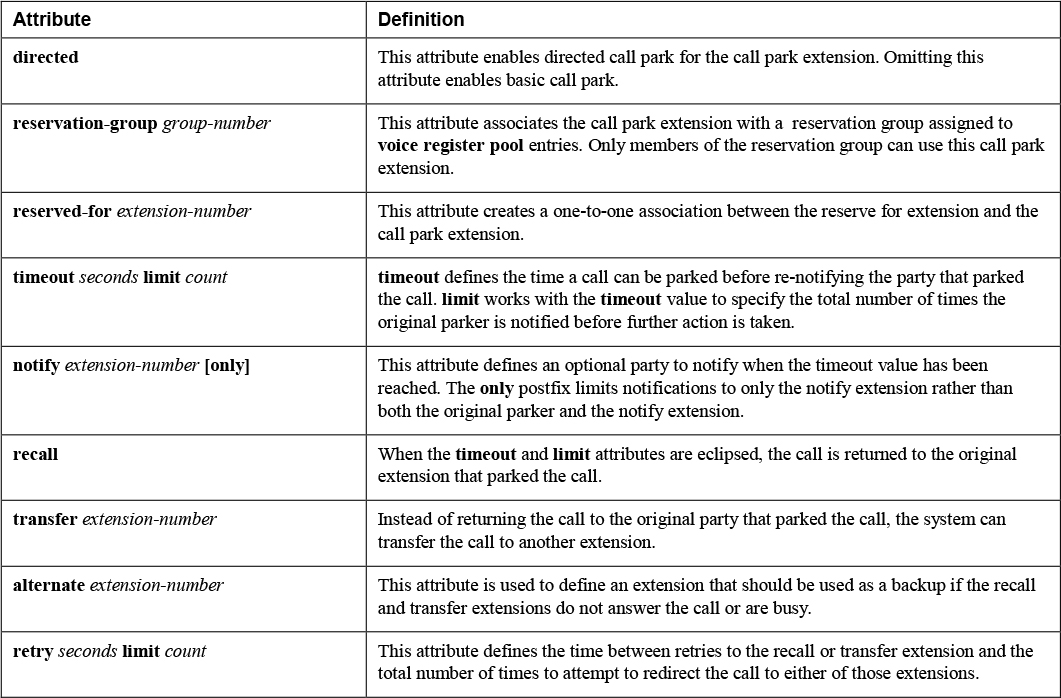
Note
The reservation-group and reserved-for attributes cannot be configured at the same time by IOS CLI as they are mutually exclusive. These attributes are checked only when parking a call, which means any device in Unified CME can any parked call. In addition, the only attribute cannot be used with the recall attribute because the two commands contradict each other.
Before you start the call park extension configuration, you need to enable call park globally for all IP phones on the Unified CME system by using the configuration shown in Example 10-38. The fac standard command is required only for directed call park, as described shortly. Remember that the max-dn command is also required; without it, the CLI does not allow the use of ephone-dn commands.
Example 10-38 Sample Global Configurations for Basic and Directed Call Park Features
! Basic Call Park
telephony-service
 max-dn 50
 call-park system application
!
! Directed Call Park
telephony-service
 max-dn 50
 call-park system application
 fac standard
!
Example 10-39 shows a basic call park configuration and a directed call park configuration for two ephone-dn entries. The first, ephone-dn 2, specifies a basic call park slot with no optional attributes. The name of the park slot is used for caller ID purposes if a recall, transfer, or alternate transfer occurs. The second park slot, ephone-dn 3, is a directed call park slot with no optional attributes. The number command for both park slots defines the park slot extension used to retrieve the parked call.
![]()
Example 10-39 Sample Basic and Directed Call Park Configurations
! Basic, uses park softkey
ephone-dn  2
 number *7777
 park-slot
 name 7777-PARK
!
! Directed, uses transfer softkey
ephone-dn  3
 number *8888
 park-slot directed
 name 8888-PARK
!
Example 10-40 shows the same two park slots as Example 10-39 but with additional optional parameters added to the park-slot command. Here park slot extension 7777 would attempt to notify extension 8888, and then, after the call had been parked for 10 seconds, it would attempt to notify the original extension (7777) that parked the call. This timeout notification occurs twice, and the third timeout results in the parked call attempting to transfer to extension 1111. If this transfer cannot be completed, an alternate transfer to 9999 occurs.
For the second park slot extension, 8888, the call parked on the directed call park slot times out after 120 seconds. The first timeout results in notification of only 7777 (because the only attribute is specified). On the second timeout, which is 120 seconds, the parked call attempts to transfer to extension 2222.
Example 10-40 Sample Advanced Use of the park-slot Command for Basic and Directed Call Park
! Basic, uses park softkey
ephone-dn  2
 number *7777
 park-slot timeout 10 limit 3 notify 8888 transfer 1111 alternate 9999
 name 7777-PARK
!
! Directed, uses transfer softkey
ephone-dn  3
 number *8888
 park-slot directed timeout 120 limit 2 notify 7777 only transfer 2222
 name 8888-PARK
!
As one can see, there are many ways to configure the park slot extension and ensure that a call is not parked indefinitely. You can use the information in Example 10-37 and Table 10-2 along with the question mark command (?) to find the exact configuration that works for your business needs.
Typically, the customer can choose the number to use for the call park extension. For example, a customer might choose to use a one-to-one mapping so that each extension on the system has a call park extension. With this configuration, the call park extension is usually prefixed by some value, such as * or #, to differentiate it from the actual extension. Alternatively, a customer might carve out a range of extensions that are entirely dedicated to parking calls, and they might then be assigned to specific departments or sections of the organization.
Call Park Retrieval
![]()
As mentioned in the previous section, any device can retrieve an active parked call; however, the actions required to retrieve a parked call depend on the type of park slot being used. For example, a call parked using the basic call park feature can be retrieved by either clicking the Resume softkey on the IP phone that parked the call or dialing the call park extension directly. Unified CME works to unpark the call and connect it to the IP phone.
To retrieve a call parked using the directed call park feature, you dial the directed call park retrieval feature access code (FAC), along with the call park extension, from the phone where you would like to retrieve the call. The default directed call park retrieval FAC is *0, which means a call that was parked by being transferred to the directed call park extension *8888 would be retrieved by using *0*8888 (the directed call park retrieval FAC plus the directed call-park extension). Example 10-41 shows how to verify the current FAC configuration by using show telephony-service fac. This example also shows that the default can be changed to any value, as defined with the fac custom dpark-retrieval command via telephony-service. If fac standard is already configured, you need to remove it by using the no prefix. Attempting to configure fac custom along with fac standard prompts an error message that instructs you to remove fac standard before proceeding.
Example 10-41 Verification and the Configuration Required to Change the FAC for Directed Call Park Retrieval
rtp-cme# show telephony-service fac
  telephony-service fac standard
    callfwd all **1
    callfwd cancel **2
    pickup local **3
    pickup group **4
    pickup direct **5
    park **6
    dnd **7
    redial **8
    voicemail **9
    ephone-hunt join *3
    ephone-hunt cancel #3
    ephone-hunt hlog [N/A for SIP] *4
    ephone-hunt hlog-phone *5
    trnsfvm *6
dpark-retrieval *0
    cancel call waiting *1
    ephone-hunt unjoin #4

rtp-cme(config)# telephony-service
rtp-cme(config-telephony)# fac custom dpark-retrieval #5
Remove fac standard first!
rtp-cme(config-telephony)# no fac standard
fac standard has been disabled!
rtp-cme(config-telephony)# fac custom dpark-retrieval #5
fac dpark-retrieval code has been configurated to #5!

rtp-cme# show telephony-service fac
  telephony-service fac custom
dpark-retrieval #5
When troubleshooting issues related to both basic call park and directed call park, you can use the following show and debug commands to gather information about the issue:
!
show ephone-dn park
!
debug ephone park-pickup
debug voip application park-pickup
debug ccsip mess
debug ccsip error
!
Survivable Remote Site Telephony (Unified SRST)
Unified SRST serves as a backup call agent for endpoints that reside at remote locations. These endpoints are likely to register with Unified CM over a WAN connection for normal operations. In the event of a connection outage with the remote Unified CM servers, an IP phone may register with the Unified SRST gateway. The Unified SRST gateway provides limited services and features to ensure business continuity while mitigating customer satisfaction issues that arise from network down situations.
Unified SRST has two modes of operation, which have different feature sets:
• Traditional Unified SRST: This is the default voice register global mode when no mode command has been enabled. This operational mode offers basic calling features for IP phones and no feature support.
• Unified Enhanced SRST (Unified E-SRST): This is an updated version of Unified SRST that includes new features such as shared lines, voice hunt groups, Busy Lamp Field (BLF), and video support. For modern deployments, this is the mode that should be used.
Figure 10-3, shown earlier in this chapter, shows a simple network design with a centralized Unified CM server. The remote branch location also leverages a Cisco IOS gateway that doubles as a Unified SRST gateway. Here the IP phones register with Unified CM over the WAN connection. Unified CM is configured to advertise its primary, secondary, and tertiary call agents for registration as per the Unified CM group configuration assigned to a phone’s device pool. In addition to these three points of redundancy, the device pool can also be configured with a Unified SRST reference as a backup. If an IP phone is unable to communicate with any of the provided call agents, the Unified SRST reference is contacted, and the IP phone initiates the registration process with the IOS gateway.
The following sections discuss how to configure Unified SRST on both Unified CM and the IOS gateway and the commands you can use to verify proper Unified SRST failover.
Implement SIP Unified SRST on Unified CM
The task of implementing Unified SRST on Unified CM is a straightforward one that involves a few key steps:
![]()
Step 1. Create a Unified SRST reference by navigating to System > Unified SRST and configuring the reference as shown in Figure 10-4. The key items are the IP Address and SIP Network/IP Address fields. The IP Address Field is used for SCCP IP phones, and the SIP Network/IP Address field is utilized by SIP IP phones. These IP Address fields should reference an IP address assigned to an active interface on the Unified SRST gateway.
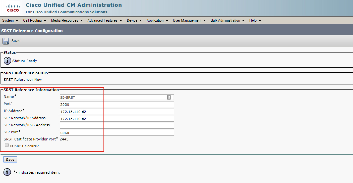
Figure 10-4 Unified CM Unified SRST Reference Configuration Page
Step 2. Assign the Unified SRST reference to the SJ-Unified SRST-DP device pool, as shown in Figure 10-5. Leave all the other settings at their defaults.
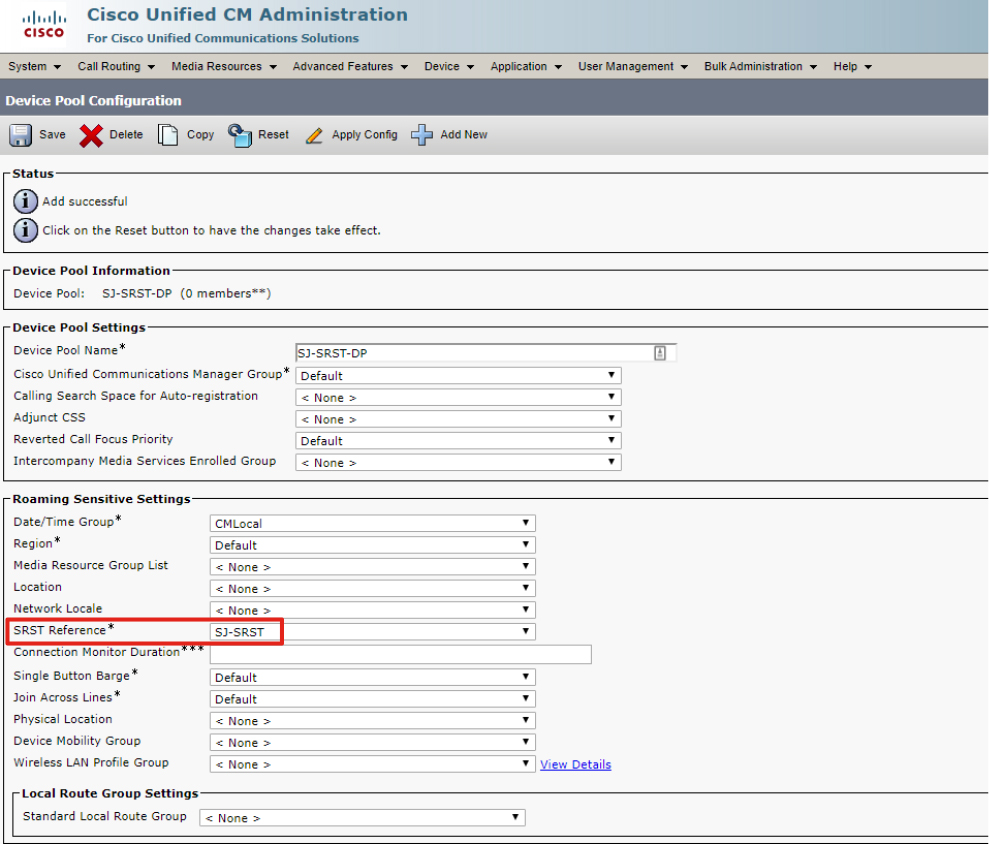
Figure 10-5 Unified CM Unified SRST Reference Application on Device Pool
Step 3. Assign the device pool to all the Unified CM IP endpoints that might need to use this Unified SRST gateway. Figure 10-6 shows the addition of the SJ-Unified SRST-DP device pool to a test phone.

Figure 10-6 Device Pool Application to an IP Phone
Step 4. Save IP phone page and apply the configuration so the endpoint pulls the new configuration.
Implement SIP Unified SRST on an IOS Gateway
![]()
Example 10-42 shows the full configuration required to implement Unified SRST for SIP IP phones. A few settings should look familiar from earlier in the chapter, when you saw how to manually register a SIP phone. For older versions of Unified CME (before Version 12.6), you configure the ip address trusted list command to allow SIP message processing on the IOS gateway. Next, you use the allow-connections command to enable SIP-to-SIP calling functionality. Finally, you use the registrar server command to allow the processing of SIP REGISTER requests on the Unified SRST gateway.
Next, you set voice register global to the Unified E-SRST (esrst) mode and define the maximum number of phones (max-pool) and directory numbers (max-dn). Next, you need to define the optional system message that appears on the IP phone display during Unified SRST registration.
Note
Refer to the Unified SRST compatibility matrix for detailed information about the total number of IP phone registrations different IOS gateways can handle: https://www.cisco.com/c/en/us/td/docs/voice_ip_comm/cucme/requirements/guide/33matrix.html.
Finally, you need to create a voice register pool that references an IP address network where the IP phones reside. In modern Unified CME versions, this is used to dynamically update the IP trusted list feature when running debug voip iptrust, as shown in Example 10-43. With this configuration in place, if a SIP IP phone attempts to register from this IP subnet, Unified CME automatically creates dial peer information and registers the endpoint.
Example 10-42 Configuration for Unified SRST on an IOS Gateway
! Step 1
voice service voip
 ip address trusted list
  ipv4 14.50.214.0 255.255.255.0
 allow-connections sip to sip
 sip
  registrar server
!
! Step 2
voice register global
 mode esrst
 system message Unified SRST MODE
 max-dn 50
 max-pool 50
!
! Step 3
voice register pool  1
 id network 14.50.214.0 mask 255.255.255.0
!
Tip
There are no major differences between the configuration of Unified CME hunt groups and the configuration of Unified SRST hunt groups. When configuring Unified SRST hunt groups, always enable the members logout command on all voice hunt groups. Because the Unified SRST gateway and Unified CM do not share stateful information about hunt groups, there is a chance that without this command, an agent will be logged in upon failover to Unified SRST although that agent was originally logged out before the Unified SRST registration. With the members logout command in place, all agents start in the logout state.
Verify and Troubleshoot SIP Unified SRST Failover
To perform verification of Unified SRST configurations, you can simulate a WAN outage by applying an ACL used to block TCP traffic to specific Unified CM servers close to the phone. This forces the IP phone to initiate registration with the Unified SRST gateway. In a lab network, you can simply disable the CallManager service to disable SIP registration and force the IP phone to fail over to the Unified SRST gateway.
Before attempting Unified SRST testing, you should ensure that the IP phone has downloaded the latest configuration and knows about the Unified SRST reference. The easiest way to verify whether this has occurred is through the IP phone web page and the Network Setup tab. In order to view the IP phone web page, you set the Web Access option in the Product Specific Configuration Layout section of the IP phone configuration page in Unified CM to Enabled. On the Network Setup tab, the last Unified CM server should reference the IP address of the Unified SRST gateway. Figure 10-7 shows an IP phone web page with the active Unified CM and Unified SRST designated as Standby.

Figure 10-7 Verifying the IP Phone Registration Pre-Unified SRST Failover
You can examine the Unified SRST configuration by issuing the show voice register global command. Example 10-43 shows the verification of the Example 10-42 configuration. To view the dynamic trusted list feature, you use the command show ip address trusted list can be leveraged, which is also included in Example 10-43.
Example 10-43 Verifying Unified SRST and the Dynamic Trusted List
sj-srst# show voice register global
CONFIG [Version=12.6]
========================
  Version 12.6
  Mode is esrst
  Max-pool is 50
  Max-dn is 50
  System message is Unified SRST MODE
sj-srst# show ip address trusted list
IP Address Trusted Authentication
 Administration State: UP
 Operation State:      UP

IP Address Trusted Call Block Cause: call-reject (21)

VoIP Dial-peer IPv4 and IPv6 Session Targets:
Peer Tag        Oper State      Session Target
--------        ----------      --------------

Configured IP Address Trusted List:
ipv4 14.50.214.0 255.255.255.0
Dynamic IP Address Trusted List:
IP Address                                   Subnet Mask     Count Reason
-------------------------------------------- --------------- ----- ----------------
ipv4:14.50.214.0 255.255.255.0 1 Pool Configured
sj-srst# show log
Nov 19 18:54:21.258 EST: %PARSER-5-CFGLOG_LOGGEDCMD: User:cisco  logged command:voice register pool 1
Nov 19 18:54:32.479 EST: iptrust_findDynamicListEntry: Trying to find ip[14.50.214.0] mask [255.255.255.0] in Dynamic Trust list
Nov 19 18:54:32.479 EST: iptrust_findDynamicListEntry: Dynamic list is not populated yet
Nov 19 18:54:32.479 EST: iptrust_addDynamicListEntry: successfully added
Nov 19 18:54:32.479 EST: %PARSER-5-CFGLOG_LOGGEDCMD: User:cisco  logged command:id network 14.50.214.0 mask 255.255.255.0
After the failover has occurred, you can consult the same IP phone web page to verify whether the Unified SRST gateway is now the active device. Figure 10-8 provides a screenshot of a phone that has now registered with the Unified SRST gateway. You can use the command show voice register pool all brief to view registered SIP endpoints and the show voice register pool pool-tag command to view registration information and other useful information for the Unified SRST reference pool. Example 10-44 provides a truncated version of this command’s output.
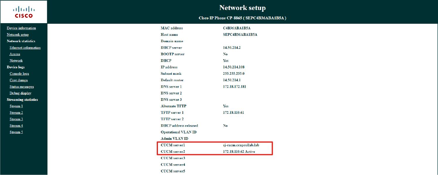
Figure 10-8 Verifying IP Phone Registration After Unified SRST Failover
Example 10-44 Verifying Unified SRST Failover from the IOS CLI
sj-srst# show voice register pool 1
 Pool Tag 1
Config:
  Network address is 14.50.214.0, Mask is 255.255.255.0

Dialpeers created:

Dial-peers for Pool 1:
dial-peer voice 40002 voip
 destination-pattern 1000$
 session target ipv4:14.50.214.108:5060
 session protocol sipv2
 digit collect kpml
  after-hours-exempt   FALSE
Statistics:
  Active registrations  : 1

  Total SIP phones registered: 1
  Total Registration Statistics
    Registration requests  : 1
    Registration success   : 1
sj-srst# show voice register pool all brief
Pool ID                IP Address        Ln DN  Number               State
==== ================= ================= == === ==================== ============
1 14.50.214.0 14.50.214.108 1000$ REGISTERED
Cisco IP phones registered to an Unified SRST gateway attempt to open a TCP connection with the original call agents every 120 seconds, as defined by the Unified CM Connection Monitor Duration enterprise parameter or device pool parameter. This means that when an IP phone registers with an Unified SRST gateway, the device does not attempt to reregister with any of the original three call agents until the Connection Monitor Duration timer has expired. One issue that may arise with a lossy WAN connection is “flapping” of IP phone registration between the Unified CM servers and the Unified SRST gateway. In this situation, the Connection Monitor Duration timer should be set to a much higher value to reduce the number of back-and-forth registrations experienced by the IP phones.
References
Cisco Unified Communications Manager Express 11.5 Data Sheet, https://www.cisco.com/c/en/us/products/collateral/unified-communications/unified-communications-manager-express/datasheet-c78-737647.html
Cisco Unified Communications Manager Express System Administrator Guide, https://www.cisco.com/c/en/us/td/docs/voice_ip_comm/cucme/admin/configuration/manual/cmeadm.html
Cisco Unified Communications Manager Express System Administrator Guide, “Cisco Unified CME Features Roadmap,” https://www.cisco.com/c/en/us/td/docs/voice_ip_comm/cucme/admin/configuration/manual/cmeadm/cmeroad.html
Cisco Unified Communications Manager Express System Administrator Guide, “Virtual CME,” https://www.cisco.com/c/en/us/td/docs/voice_ip_comm/cucme/admin/configuration/manual/cmeadm/cmevir.html
Cisco Unified SCCP and SIP SRST System Administrator Guide, https://www.cisco.com/c/en/us/td/docs/voice_ip_comm/cusrst/admin/sccp_sip_srst/configuration/guide/SCCP_and_SIP_SRST_Admin_Guide.html
Cisco Unified Survivable Remote Site Telephony Data Sheet, https://www.cisco.com/c/en/us/products/collateral/unified-communications/unified-survivable-remote-site-telephony/data-sheet-c78-744126.html
Unified CME, Unified SRST, and Cisco IOS Software Version Compatibility Matrix, https://www.cisco.com/c/en/us/td/docs/voice_ip_comm/cucme/requirements/guide/33matrix.html
Exam Preparation Tasks
As mentioned in the section “How to Use This Book” in the Introduction, you have a couple of choices for exam preparation: the exercises here, Chapter 11, “Final Preparation,” and the exam simulation questions in the Pearson Test Prep software online.
Review All Key Topics
Review the most important topics in the chapter, noted with the key topics icon in the outer margin of the page. Table 10-3 lists these key topics and the page number on which each is found.
![]()
Table 10-3 Key Topics for Chapter 10
Define Key Terms
There are no key terms for this chapter.
Complete Tables and Lists from Memory
There are no memory tables or lists for this chapter.