Chapter 1. Introduction to Unified Collaboration and Dial Plans
This chapter covers the following topics:
• Introduction to Cisco Unified Collaboration Components: This section provides a crash course on the expansive Cisco Unified collaboration ecosystem and introduces the three products relevant to the CLACCM 300-815 exam blueprint and this book: Unified CM, CUBE, and Unified CME.
• Dial Plan Design Overview: This section discusses dial plans and reviews good and bad approaches to dial plan design and call routing. This section also discusses the North American Numbering Plan (NANP) and international standards, such as E.164, to provide a framework for dial plan design.
Cisco Unified Collaboration (Cisco UC) is an ever-growing ecosystem of endpoints, application servers, and peripherals that enable next-generation communication by allowing customers to communicate with audio, video, messaging, and application sharing. These collaboration devices work together to offer many solutions to real-world business problems. Cisco knows there is not a one-size-fits-all approach to solving business challenges; therefore, the Cisco collaboration solutions can be tailored to meet your exact business needs. Whether your company is big or small, the Cisco collaboration portfolio offers a cohesive experience with a feature-rich set of on-premises, cloud, and cloud hybrid collaboration products that can help take your company’s collaboration experience to the next level.
“Do I Know This Already?” Quiz
The “Do I Know This Already?” quiz allows you to assess whether you should read the entire chapter. If you miss no more than one of these self-assessment questions, you might want to move ahead to the “Exam Preparation Tasks” section of the chapter. Table 1-1 lists the major headings in this chapter and the “Do I Know This Already?” quiz questions related to the material in each of those sections to help you assess your knowledge of these specific areas. The answers to the “Do I Know This Already?” quiz appear in Appendix A, “Answers to the ‘Do I Know This Already?’ Quiz Questions.”
Table 1-1 “Do I Know This Already?” Foundation Topics Section-to-Question Mapping

1. Which products exist within the collaboration edge component of the Cisco collaboration ecosystem? (Choose two.)
a. Unified CM
b. Cisco Unified Border Element (CUBE)
c. Expressway-C
d. Unified CME
e. Cisco Unity Connection (CUC)
2. Which voice over IP (VoIP) protocol is used to form trunks between many of the different collaboration components for call routing and other features?
a. Q.931
b. Session Initiation Protocol (SIP)
c. Real-Time Transport Protocol
d. Hypertext Transfer Protocol (HTTP)
3. Which of the following are Unified CM services? (Choose two.)
a. Endpoint registration
b. Ad hoc conferencing
c. Firewall traversal
d. PSTN SIP trunk termination
4. For which VoIP protocols does CUBE perform interworking? (Choose two.)
a. MGCP
b. SCCP
c. SIP
d. H.323
e. WebRTC
5. What part of the North American Numbering Plan (NANP) deals with area codes?
a. NPA
b. NXX
c. Subscriber
d. Country code
6. Which of the following is a valid +E.164 number for San Jose, California?
a. 5267209
b. 4085267209
c. 14085267209
d. +14085267209
7. What sequence of digits would an on-premises NANP user typically dial to indicate that an international call should be made?
a. Steering code and phone number
b. Steering code and 1 and the phone number
c. Steering code and 00 along with the country code and the phone number
d. Steering code and 011 along with the country code and the phone number
Foundation Topics
Introduction to Cisco Unified Collaboration Components
In this book, you will be introduced to a number of Cisco collaboration solutions, including many different products working together to achieve a common goal. Cisco’s on-premises and cloud collaboration solutions offer organizations the ability to integrate video and audio across many different devices and locations.
Figure 1-1 provides an example that shows the Cisco collaboration ecosystem’s major segments or subsystems.

Figure 1-1 Cisco UC Architecture Overview
Figure 1-1 shows the following components:
• Cisco Unified Communications Manager (Unified CM) is a call control application that handles endpoint registration, call routing, supplementary features, and many other services. In addition, instant messaging and presence (IM&P) services for Cisco Jabber clients are handled by an IM&P server that works alongside Unified CM.
• Cisco Unity Connection (CUC) handles enterprise voicemail services and also provides other features, such as basic auto-attendant functionality, through call handlers.
• Conferencing is a large part of any collaboration ecosystem, and Cisco has a few on-premises products that work together to provide a feature-rich on-premises conferencing platform:
• Cisco Meeting Server (CMS) can be used to provide highly scalable audio and video conferencing options to on-premises endpoints and mobile devices.
• Cisco Telepresence Management Suite (TMS) can be coupled with CMS to manage video conferencing devices on the network along with centralized meeting scheduling.
• Cisco Meeting Manager (CMM) provides a set of management services built around CMS. (CMM is not shown in the figure.)
• IOS and Unified CM–based ad hoc conferencing provide audio-only conferencing for on-premises endpoints.
• Collaboration management applications such as Cisco Prime Collaboration Deployment (PCD) assist UC engineers with deployment, migration, and installation of collaboration applications, and Prime Collaboration Provisioning (PCP) provides a centralized location to perform move, add, change, and delete operations for various system configurations, endpoints, and users.
• Endpoints include desktop endpoints such as the Cisco IP Phone 7800 and 8800 Series and desktop video conferencing units such as the DX80 and Webex Desk Pro. Softphone applications such as Cisco Jabber and Webex Teams can be leveraged for calling, meeting, or instant messaging features.
• At the collaboration edge, a few key products service two key areas:
• Connecting the enterprise to the PSTN so that on-premises endpoints can call off-net mobile devices such as a cellphones or receive inbound calls to endpoints, conferencing services, interactive voice recognition (IVR) applications, and voicemail: Public switched telephone network (PSTN) connectivity is achieved through Cisco Unified Border Element (CUBE), which connects to an Internet telephony service provider (ITSP) to provide PSTN services or through a voice gateway, which terminates a connection directly to a service provider through a traditional telephony circuit such as an Integrated Service Digital Network (ISDN) connection.
• Enabling Mobile and Remote Access (MRA) for teleworkers and mobile worker devices to register the on-premise Unified CM and leverage other collaboration services on the enterprise domain: The Expressway-C and Expressway-E series of devices facilitate firewall traversal and connection to mobile teleworker devices and cloud collaboration systems via the public Internet. An Expressway-E device is usually placed in a DMZ and communicates to an Expressway-C device, which is located inside the corporate firewall. MRA endpoints can register to on-premises call control systems such as Unified CM without the need for costly virtual private network (VPN) connections. Expressway also provides business-to-business (B2B) collaboration and a unified edge for WebRTC application to connect to CMS conferences.
• In terms of cloud collaboration, Cisco has an entire suite of products under the Webex domain that can be leveraged for various purposes, such as hybrid calling services, messaging, and conferencing through Webex Calling, Webex Teams, Webex Meetings, and so on.
• Desktop endpoints at the remote site can register locally to a Cisco voice gateway running Cisco Unified Communications Manager Express (Unified CME) or register to the on-premises Unified CM over a dedicated WAN connection. In the event that this WAN connection is lost, these endpoints may use the Cisco voice gateway as a backup or as a Cisco Unified Survivable Remote Site Telephony (SRST) gateway. Although not shown in Figure 1-1, Cisco Unity Express (CUE) can be used to provide voicemail functionality to Unified CME endpoints.
Note that Figure 1-1 does not show some devices, such as those in customer care solutions. The smaller Unified Contact Center Express (UCCX) can be integrated with Unified CM to provide greater IVR capabilities to callers, including advanced custom scripting and support for up to 400 agents. Situations in which more agents are required can take advantage of the more robust Unified Contact Center Enterprise (UCCE), which is an entire architecture that has many unique components. (UCCE is not shown in Figure 1-1.)
Figure 1-2 rearranges the components shown in Figure 1-1 into a network topology that you might be more familiar with. Here you can see two Unified CM clusters, accompanied by a set of on-premises endpoints that register to the local Unified CM cluster. These two clusters can be configured to communicate via a SIP trunk, which can be used by either cluster to connect to shared services such as IM&P, CUC, CMS, and TMS. Similarly, Skinny Client Control Protocol (SCCP) can be used to register IOS-based media resources.
![]()

Figure 1-2 A Common Cisco UC Topology with Collaboration Components
The Unified CM cluster can also leverage SIP or H.323 to form a trunk with CUBE, which in turn uses a SIP trunk with the service provider of choice for PSTN connectivity. Mobile and remote workers can leverage the Internet, Expressway-E, and Expressway-C to communicate with on-premises resources such as Unified CM, IM&P, CMS, CUC, and on-premises endpoints. MRA endpoints can even take advantage of CUBE when making PSTN calls.
The remote site has the option to leverage a SIP trunk directly to the service provider and, ultimately, to the PSTN; alternatively, remote site endpoints can register over an MPLS WAN connection back to the on-premises resources for registration, supplementary services, and PSTN connectivity. Both connectivity options are provided by a Cisco Integrated Services Router (ISR) configured as a Unified CME or as a data router providing WAN connectivity to the enterprise.
There are many components involved in a Cisco UC solution, and a UC administrator will likely come across many of these components in real-world deployments. Unfortunately, with so many different components, there are far too many configurations, scenarios, and situations to discuss in a single book. Therefore, this book focuses on the three main products required for the CCNP CLACCM 300-815 exam, according to the exam blueprint:
• Unified CM: Unified CM accounts for almost half of the blueprint, with major focus on call control, dial plans, call control features, and unified mobility options. These topics are covered in detail in Chapters 4, “Unified CM Call Routing and Digit Manipulation,” through 7, “Unified CM Mobility,” of this book. Note that Chapter 5, “Unified CM SIP Trunk Configuration,” discusses many of the SIP trunking configuration items that are required on Unified CM to integrate with the shared services applications, such as IM&P, CUC, and CMS, but it does not cover the configurations on those products.
• CUBE: IOS dial plans, digit manipulation, and CUBE interworking features for SIP and media are discussed in Chapters 8, “CUBE Call Routing and Digit Manipulation,” and 9, “CUBE Interworking Features.”
• Unified CME and Unified SRST: Unified CME and Unified SRST are covered in Chapter 10, “Unified CME and SRST.”
Various chapters provide deeper treatment of these products and their features, as well as their configuration, operation, and troubleshooting. This chapter provides a quick introduction to these three products.
Cisco collaboration products use many voice over IP (VoIP) protocols. This book focuses on the main protocols included in the CLACCM 300-815 exam blueprint:
• Session Initiation Protocol (SIP) and Session Description Protocol (SDP): While Chapter 2, “VoIP Protocols: SIP and H.323,” provides a comprehensive overview of the SIP, every chapter of this book covers SIP to some degree. For example, in Figure 1-2 you can see that almost every product in the Cisco UC ecosystem uses SIP for communication in some capacity. Similarly, SDP is very important to SIP communications and is examined, along with SIP, throughout this book.
• H.323: H.323 consists of several different protocols—most importantly H.225 and H.245. H.323 is covered in Chapter 2 as well as in Chapter 9.
• Real-Time Transport Protocol (RTP) and Real-Time Transport Control Protocol (RTCP): Chapter 3, “VoIP Protocols: RTP, RTCP, and DTMF Relay,” provides a rigorous introduction to RTP (audio and video media) and RTCP. Later chapters, such as Chapter 5, “Unified CM SIP Trunk Configuration,” Chapter 6 “Unified CM Call Control Features,” and Chapter 9, dive into specific configurations on Unified CM and CUBE for media interworking and troubleshooting.
• Dual-tone multifrequency (DTMF): The various protocols defining DTMF relay are covered in Chapter 3, and DTMF interworking on CUBE is discussed in Chapter 9.
Note
Due to the content of the CLACCM 300-815 exam blueprint, this book assumes that common networking components, such as Layer 3 IP routing and Layer 2 components, have been properly configured. Furthermore, foundational topics related to most UC networks—such as Domain Name System (DNS), Dynamic Host Configuration Protocol (DHCP), Lightweight Directory Access Protocol (LDAP) and Active Directory, Network Time Protocol (NTP), Cisco Discovery Protocol (CDP), and Trivial File Transfer Protocol (TFTP)—are left to the CCNP CLCOR (300-801) exam.
Unified CM
Cisco Unified CM is at the heart of every on-premises Cisco collaboration solution for the modern enterprise. As such, UC engineers are likely to need to deploy, administer, or troubleshoot Unified CM at some point during their collaboration journey. Almost half the topics in the CLACCM 300-815 exam blueprint are relevant to Unified CM.
Unified CM has far too many features and services to provide an exhaustive list within this publication. The following are some of the features you are most likely to encounter:
![]()
• Unified CM can provide call agent registration and call routing capabilities for many different models of voice and video endpoints, such as Cisco IP Phone endpoints, Webex endpoints, analog telephony adapters (ATAs), immersive room systems, soft clients, and many other devices.
• Unified CM can integrate with many different Cisco products and third-party devices to extend features, services, and call routing capabilities using VoIP protocols such as SIP, H.323, MGCP, and SCCP. SIP trunking is discussed in Chapter 5.
• Unified CM has the ability to provide media-related services such as software conference bridges, Media Termination Points (MTP), Music on Hold (MOH), and basic IVR functionalities with integrations to other devices such as CMS or IOS XE voice gateways equipped with PVDMs to provide additional media services. A few of these topics are covered in Chapters 6 and 9.
• Unified CM can be configured to provide native call hunting, time-of-day routing, and queuing abilities or integrated with UCCX for customer care or contact center functions. For situations where an even larger solution is required, Unified CM is also integral in UCCE deployments. Chapter 4 covers the features native to Unified CM.
• Unified CM has a rich set of application programming interfaces (APIs) that can be used to integrate with custom applications for extended call routing, call recording, and serviceability.
• Unified CM can integrate with Microsoft Active Directory (AD) using LDAP for user management and authentication.
• Unified CM features many bulk administration options, which can be further expanded by integrating PCD or PCP.
• Unified CM provides supplementary services to IP phones, such as hold, resume, transfer, park, pickup, call forward, malicious call identification, and shared lines. Chapter 9 discusses some of these topics and how they pertain to CUBE integrations.
• Unified CM provides many features that make administration and deployment of endpoints a breeze. These include auto-registration, self-provisioning, and DHCP services.
• Unified CM provides many mobility options to provide flexibility for end users, such as Extension Mobility, Mobile Connect/Single Number Reach (SNR), Move to Mobile, Mobile Voice Access (MVA), Device Mobility, and Mobile and Remote Access (MRA) through Expressway for a VPN-less solution to registering endpoints over the public Internet. Chapter 8 covers most of these topics, except for MRA, which is left for the CCNP Collaboration CLCEI 300-820 exam.
• End users can update their local speed dial, forwarding, and mobility settings through an easy-to-use self-care portal.
• Unified CM provides many next-generation security features that can be used to encrypt call signaling and media along with other traffic to and from the server. In addition, many security features that are enabled by default work to protect devices during many key operations, such as configuration download and endpoint registration. Administrators can also control user roles to limit access and operations on a per-account basis.
• Unified CM provides many troubleshooting and diagnostic capabilities through the Real-Time Monitoring Tool (RTMT). A crash course on using RTMT for log analysis for call routing is provided at the end of Chapter 4, and Chapters 5 through 7 also provide relevant trace snippets gathered from RTMT.
Unified CM operates as a virtual machine running on an ESXi hypervisor and Cisco Unified Computing System (UCS). This combination is often referenced as Cisco UC on UCS. Unified CM may operate as a standalone virtual machine or may be clustered to scale to business needs. Depending on the requirements of your enterprise, you might see something smaller than what is detailed in Figure 1-3, or you might see something even larger! In this sample cluster, a single Unified CM publisher is responsible for the master copy of the database. The Unified CM TFTP pairs are used to load balance TFTP requests from endpoints and provide redundancy in the event of a node failure. The Unified CM publisher does not provide call processing (or TFTP) capabilities as it is busy with the database. Instead, one or more Unified CM call processing node pairs are leveraged to handle endpoint registration, call routing services, and other features. Further redundancy can be provided by geographically locating the redundant call processing and TFTP nodes in different data centers. IP Phone registration should be equally load balanced across these call processing nodes to better utilize virtual machine resources. There are many constraints on how to create a Unified CM cluster, and you can refer to the Unified CM Solution Reference Network Designs (SRND) documents for more information. A smaller deployment may have just one or two servers in a cluster, with database, TFTP, and call processing services running on the one or two servers in the cluster. Which services run on which servers in the cluster is left up to the administrator to determine, based on design guidance offered in the SRND.
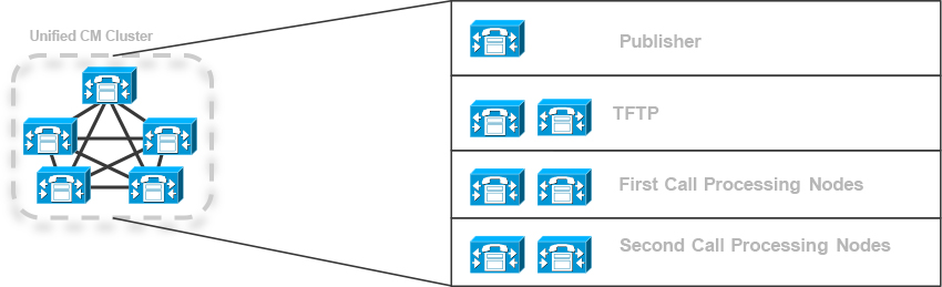
Figure 1-3 One Publisher, Two TFTPs, and Two Call Processing Pairs (Four Call Processing Subscribers)
Depending on the size of the enterprise, there may be more than one Unified CM cluster. A Session Management Edition (SME) cluster may be deployed alongside the Intercluster Lookup Service (ILS) to provide dial plan aggregation and ease the administrative overhead that occurs in this type of situation. An SME cluster is nothing more than a Unified CM cluster with no phones registered. Its primary goal is to aggregate connections from other Unified CM clusters, typically referred to as leaf clusters. Figure 1-4 shows three clear clusters of various sizes integrated with an SME cluster for centralized dial planning. ILS and Global Dial Plan Replication are discussed in Chapter 4.

Figure 1-4 Three-Cluster SME Design
Unified CM is a very powerful product on its own, and when it is integrated with other Cisco collaboration solutions, it gains even more capabilities. The next section discusses how CUBE can be deployed alongside Unified CM to integrate with public IP networks for PSTN connectivity.
Cisco Unified Border Element
CUBE, much like Unified CM, is often included in collaboration deployment solutions for enterprise PSTN access and customer contact center solutions. As a result, UC engineers are likely to need to deploy, configure, or troubleshoot calls involving CUBE or IOS voice gateways at some point. CUBE is an IOS/IOS XE-based application that runs on both physical and virtual hardware such as the Integrated Services Router, Aggregated Services Router, and Cloud Services Router. The different platforms allow CUBE to scale to different total session capacities and cater to the needs of an individual business. As a result, when selecting a platform to run CUBE, UC administrators must carefully map out the total number of sustained inbound/outbound sessions along with the total number of new calls per second that CUBE will be expected to handle. This must be done to avoid oversubscribing the resources on the device. As with most other deployment planning, room should be left for future growth. In addition to VoIP session capacity planning, you must consider what other services the platform will be handling. Cisco routing platforms can operate many other services alongside CUBE, and those services use the same CPU and memory resource pools. Depending on the services, utilization, and other requirements, a UC administrator must make a choice to either run all the services on one device and account for these other services in the session capacity planning or split the CUBE functionality into a separate device that allows total resource allocation to the CUBE application.
The CUBE application and the SIP and H.323 protocols operate logically within the OSI model at the application layer (Layer 7). To establish a session, CUBE encapsulates SIP traffic into packets as application data for transmission over Layer 3 IP networks. This means a valid bidirectional Layer 3 network path needs to be established between CUBE and any device that CUBE peers with. The type of physical connections and routing protocols to be used are determined by the underlying network used to transmit these packets for establishing SIP sessions. Some deployments with CUBE may require only a few static routes, while others may require deployment of a fully autonomous routing protocol, such as BGP. The network connection with an ITSP may be a direct point-to-point Ethernet connection or a serial connection, or CUBE may be required to peer over a WAN connection, such as MPLS. On the LAN side, the same complexities (or more) may exist. In addition, advanced IP routing techniques such as virtual routing and forwarding (VRF) may be required.
Furthermore, because CUBE is on the edge of the network and acting as a demarcation point between the private enterprise LAN and various public networks, most UC deployments utilize a firewall for additional security, protection, and threat mitigation. The firewall functionality may be colocated with CUBE via zone-based firewall (ZBFW) or a standalone device such as a Cisco Adaptive Security Appliance. The Layer 1, 2, 3, and 4 network design and deployment topics for CUBE are not required by the CLACCM 300-815 exam blueprint, so they are not covered in this chapter. All examples and scenarios in this chapter assume that a bidirectional network path and the required configurations to facilitate that network path have already been completed.
Figure 1-5 illustrates a few different CUBE deployment scenarios to help visualize how CUBE fits into an IP network and facilitates interworking with the private enterprise LAN and public networks through an ITSP. CUBE may be deployed as a centralized resource for many Unified CM clusters (alongside a Unified CM SME cluster) to interface with the PSTN or be distributed across many Unified CM clusters due to geographic location. CUBE can be configured as an active/passive high availability pair to provide redundancy and failover of ongoing calls in the event of a link failure.
![]()

Figure 1-5 CUBE Integrating with a Service Provider and Unified CM for Different Deployment Scenarios
The main goal of CUBE is to operate as a session border controller (SBC) for the purpose of performing call routing functions between the enterprise and remote public networks. If required, administrators can use many of the rich CUBE interworking features to handle interoperability scenarios when interfacing with third-party devices. These features are discussed in depth in Chapter 9.
CUBE has many other features that can be used to provide call signaling, media security, call recording, media forking, DTMF interworking, multi-tenant operations, fax detection, and media transcoding. Chapter 8 will provide an in-depth examination of call routing and digit analysis in CUBE, but for more information about these other features, refer to the Cisco Press book Understanding Session Border Controllers: Comprehensive Guide to Designing, Deploying, Troubleshooting, and Maintaining Cisco Unified Border Element (CUBE) Solutions.
Unified CME and Unified SRST
Unified CME is a great remote branch office or even a small to medium business call agent solution that leverages IOS or IOS XE voice gateways on the ISR series of hardware routers or Cloud Services Router virtual machines. Like Unified CM, Unified CME offers many call agent, registration, and call routing capabilities for on-premises IP phone endpoints. Administrators and end users can leverage many supplementary service features available to IP phones, although there are not as many as with Unified CM. Similarly, SRST provides a redundant call agent for registration when IP phones are located at remote branch offices behind a WAN connection. For a full overview of Unified CME and SRST, see Chapter 10.
Dial Plan Design Overview
A dial plan is one of the most important parts of any collaboration solution. After all, making and receiving calls to and from various devices, applications, systems, and integrations is at the core of every UC component. Unfortunately, most UC administrators never create a dial plan from scratch because they work on or inherit an existing network where the dial plan was set up long ago. Similarly, UC administrators often employ very basic dial plan topics in their collaboration labs and do not explore the topic properly.
The following sections discuss a dial plan design for a large enterprise consisting of many geographic locations, both national and international. The following chapters reinforce the dial plan concepts with design and configuration on Unified CM, CUBE, and Unified CME.
Why Dial Plan Design Is Difficult
As an exercise, let’s examine a few scenarios that need to be addressed when designing a dial plan. We can start with an IP phone that needs to call another IP phone in a different part of the building. Both phones are registered to the same Unified CM on the same enterprise network (using on-network calling [on-net]). How do you assign phone numbers in this scenario? You might be thinking it’s as easy as using a four-digit extension and assigning the first phone the extension 1000 and the second phone extension 1001.
Now say that the IP phones require the ability to receive calls from off-network (using off-network calling [off-net]) PSTN users, such as mobile phones. To accomplish this, you should purchase a Direct Inward Dialing (DID) number from a service provider, utilize CUBE as an SBC to terminate the PSTN SIP trunk, and route the inbound call to Unified CM to reach the phone. You will likely need to do some work to get the DID number to ring the IP phone because it is unlikely that the DID number assigned by the service provider ends in 1000 or 1001. This challenge is usually solved through some form of translation that transforms the full DID number into the four-digit extension on the IP phone. To simplify this translation, you may choose to change the four-digit extension of the phones from 1000 and 1001 to match the last four digits of the DID provided by the service provider.
Now imagine that there is another site of IP phones on a different Unified CM cluster—perhaps in San Jose (SJ)—which needs the capability to call the IP phones on the first Unified CM cluster in Raleigh (RTP). How should the SJ users reach the phones in RTP? You could have the users dial out to the PSTN and route the call back in using the DID, but that is a suboptimal solution which involves hair-pinning calls through the PSTN and ultimately allocating double the call resources on your own devices responsible for PSTN calls; in addition, the users would be stuck with standard G.711 audio instead of wideband audio codecs and video. A more efficient use of resources would involve keeping the call on-net and sending it from the SJ Unified CM to the RTP Unified CM over your own network, such as an MPLS WAN. Perhaps the user could just dial the four-digit extension, but what if the last four digits of the DIDs for the two sites overlap (which is very likely to happen if you have many sites)? To deal with this challenge, you can create a private on-net dial plan that is locally significant to your enterprise. For example, the RTP site might be assigned a site code such as 191. The length of the site code is arbitrary and based on how many sites you expect to roll out in your network. A three-digit site code would give you the ability to have 1000 sites in this case. The user might dial a steering code plus a site code and the extension of the phone and utilize an on-net path over the WAN rather than off-net PSTN resources that hairpin the call.
We have not talked about steering codes yet, so let’s dive into those. How should the users at the IP phones indicate to Unified CM and other devices that the call they want to place is destined for the PSTN? For enterprise networks, this is usually signaled via a steering code, commonly referred to as a PSTN access code, that is entered before the actual called number is dialed. The most common steering code used in North American deployments is a single 9 prefixed before the dialed number to indicate that a call should be sent to an off-net PSTN destination. Some deployments in North America also utilize 8 as a steering code. In other countries, 0 is often used as the steering code. (In the upcoming chapters, you will see the steering code 9 used in most examples involving a call out to the PSTN.) Now, what steering code should be used for on-net abbreviated dialing between sites? The most common steering code here is a single 8. Your organization may have additional steering codes for various services specific to your organization. For example, overhead paging services may be accessed by dialing * and a four-digit number. Keep in mind that Unified CM has no concept of a steering digit or code as a dial plan construct. In other words, there is no place in Unified CM where you can configure anything called a steering code. Rather, steering codes are defined by use, as part of a configurable pattern.
Some customers choose to forgo steering digits altogether and require their users to place all calls the same way they would dial a number on a home or mobile device. For a phone in North America, this would mean dialing a 10-digit number for all calls, even if calling a phone in the next cubicle. While this is a perfectly valid dial plan design, it does have disadvantages, such as making it challenging to allocate phone numbers that do not have corresponding “real” PSTN numbers without causing overlap problems with the PSTN and restrictions around being able to place calls in an abbreviated fashion. In environments where users all have DID numbers and do not engage in much intra-site calling where abbreviated dialing codes are beneficial, this may be a viable option. Alternatively, you may consider using * as a steering digit to indicate abbreviated dialing. For example, dialing *1000 would reach extension 1000 in the local site while still allowing users to dial all other numbers as they would dial them from their home or mobile phone.
So far, our examples have detailed two locations in the same country along with three endpoints. It is not difficult to form a dial plan with such a small number of devices. However, in a real network, there might be thousands of endpoints at each location, all requiring DIDs that map to extensions and ring one or many phones. There may be many clusters that are spread around the globe, each serving multiple sites in different countries. In such a case, users need to dial to many different PSTN locations for local calls, long-distance calls, and international calls. As you will soon see, this process varies greatly country by country, further complicating the issue when there are multiple international locations. For these reasons, assigning a simple four-digit extension to phones may not be the most scalable approach.
In addition to the complications discussed so far, many service and emergency numbers (such as 911 or 112) exist in different geographic locations. Your organization may have many different internal services that also have phone numbers that may need to be reachable from a host of different locations, including the PSTN. Examples include auto attendants, IVR systems, customer care contact centers, multiparty conferencing numbers, and your own local IT help desk. There may be restrictions on toll-free international calls or other local restrictions on calling that need to be enforced in the dial plan. Also, don’t forget about redundancy. For business-critical services, specific phone numbers or PSTN access may require redundant paths on the network, which adds another layer of complexity to a dial plan.
When you consider all these variable requirements, constructing a dial plan from scratch can be a very daunting task. If a sound methodology is not employed from the beginning, you will likely run into issues down the road. Common problems with suboptimal dial plans include the following:
![]()
• Overlapping patterns, which lead to long wait times when dialing numbers or calls attempting to route before all the required digits have been collected.
• Calls taking suboptimal paths, which leads to resource allocation issues or quality of service problems when media takes a network path that is not engineered to carry voice or video.
• Disjointed numbering plans, which require lots of administrative overhead, result in more complex troubleshooting when issues arise, and lead to poor end-user experience.
• Customers’ expected dialing habits don’t work, resulting in call failures. For example, a customer might expect to be able to dial a local number in a certain way, but the configured dial plan might permit the call only if it is dialed as a long-distance number.
• Redundancy issues, which lead to major downtime and loss of business. Not only should these be baked into the dial plan early, they should be periodically tested. You do not want to be in the midst of an outage only to find out the redundancy is also down and has been down for quite some time.
• Inability to scale the dial plan as the company grows, undergoes a merger or an acquisition, or expands into a new country.
Luckily, various standards created by the International Telecommunication Union (ITU) provide a framework for how numbering plans work on national and international telecommunication networks. By using these standards as a starting point coupled with the Cisco Validated Design (CVD) for call control, you can begin to create a dial plan that is resilient to downtime, scalable, and, most importantly, easy to understand.
North American Numbering Plan (NANP)
The North American Numbering Plan (NANP) is used in the United States, Canada, and most Caribbean countries. For most this is likely a very familiar format. Telephone Numbers are broken into three key parts:
![]()
• Numbering plan area (NPA) codes: A numbering plan area (NPA) code, often referred to simply as an area code, is a three-digit code that is usually mapped to a location such as a city. Area codes always start with the digits 2 through 9 followed by any two digits except for two 1s.
• Central office exchange code (NXX): A central office exchange (NXX) code is another three-digit code that maps to the central office. Cities may have more than one central office code, depending on the size of the city. Much like an area code, an office code always starts with the digits 2 through 9 followed by any two digits except for two 1s.
• Subscriber numbers: A subscriber number is a four-digit extension that maps to a station.
You can put together parts of a phone number and use them with or without dashes or with parentheses to indicate digits that might not be required, depending on the location of the caller:
NPA-NXX-XXXX
NPA NXX XXXX
(NPA) NXX XXXX
Note
Note that the nomenclature used here is that for all digits after the NPA, N can be any digit from 2 to 9, and X can be any digit from 0 to 9. The digits 911 should never be used within an NPA or NXX code.
With the NANP, the parentheses are often around the area code, as the last seven digits alone can be dialed by callers in the same area code. When an area code has more than one NXX code, seven-digit dialing is usually not possible.
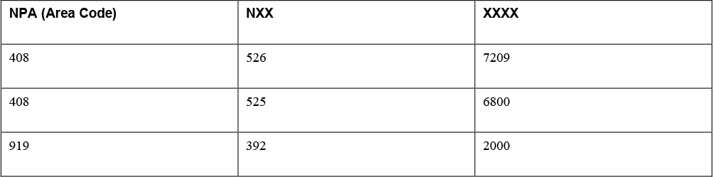
Table 1-2 provides some examples of real Cisco phone numbers. The first row of the table indicates the NPA area code 408, which is San Jose, California. The second row features the same area code but with a different NXX code. However, from the area code, you know that 408-524 and 408-526 are both located in San Jose. The last row of the table lists the Raleigh, North Carolina, area code 919, along with NXX code 392. The subscriber number in the last column is a four-digit extension that consists of digits 0 through 9 for any position.
The particular numbers in this table are all Cisco phone numbers. The number in the first row is the frontline number for Cisco TAC. The second row shows the Cisco Webex meetings call-in number. The last row shows the Cisco RTP campus number.
Table 1-2 Sample NPA and NXX Numbers from Cisco Systems
To help visualize these phone numbers and how NPA area codes and NXX numbers work, Figure 1-6 shows the numbers from Table 1-2 on a map.
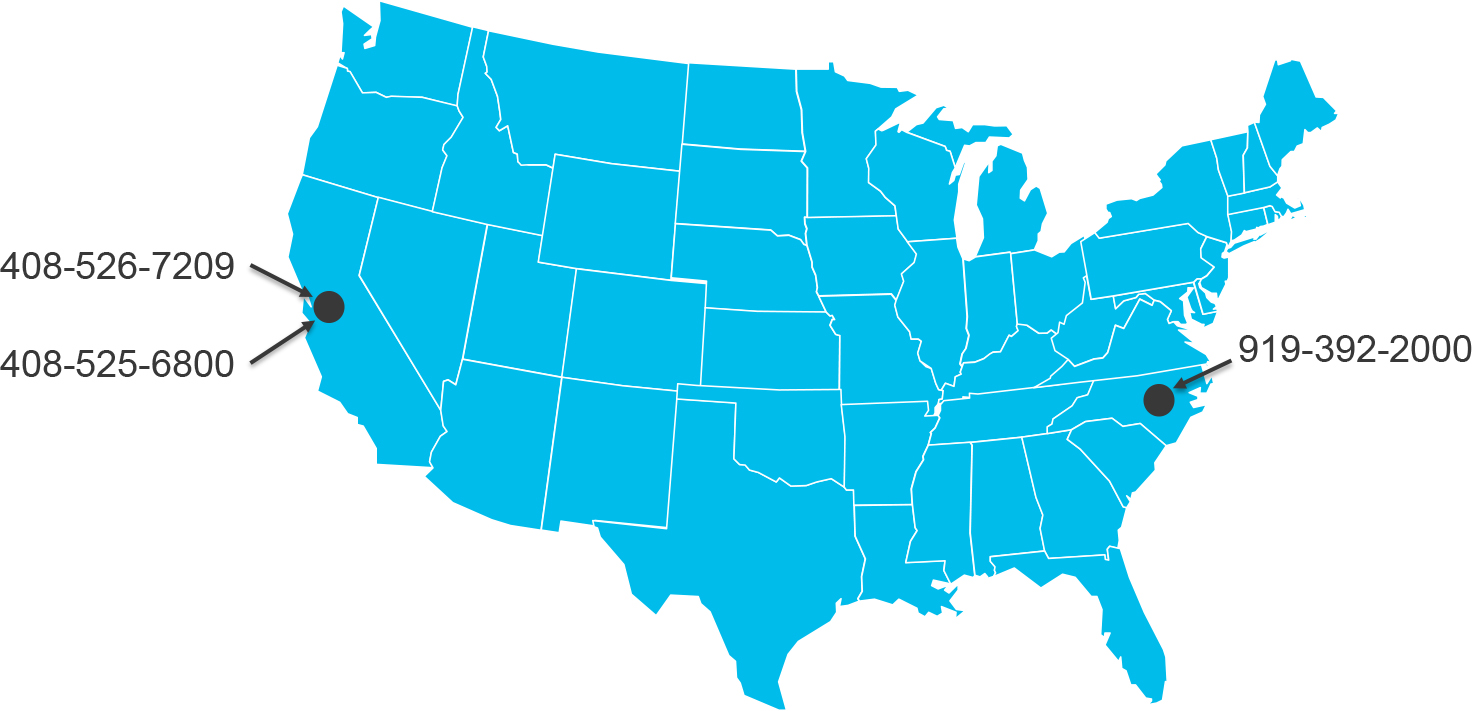
Figure 1-6 U.S. Map Showing NPA-NXX Numbers from Table 1-2
For those who have worked on collaboration systems in North America, this system likely makes sense and will seem familiar. But for those not based in the United States, there may be a learning curve. Many other countries around the world use their own structuring of numbers, and someone from the United States might struggle with the task of making local or long-distance calls or designing a national dial plan in Belgium. The next section discusses the common E.164 format for international dialing.
International Dial Plans with E.164
The ITU-T E.164 standard builds on country-specific national dialing patterns and provides a framework to easily describe phone numbers and place international calls from one country to another. This method ensures that a globally unique number exists for any phone assigned a number on the PSTN. Thanks to this standard, someone in the United States can call someone in Turkey without fear of the call being routed to another country or location, and authorities in one country can manage the numbering plan within the country without fear of conflicting with the numbering plan of another country. The E.164 standard uses country codes, and the country code is often prefixed with the plus symbol (+). An E.164 number, including the country code, cannot exceed 15 digits. Table 1-3 provides some examples of international Cisco phone numbers.
Table 1-3 International Cisco Numbers

The first row in the table shows the U.S. international country code (+1) with the national area destination code for San Jose and finally the subscriber, which is the seven-digit NXX-XXXX. The second row shows the country code for Belgium (+32) and the national destination code 2 for Brussels. A subscriber number in Belgium can take one of a few forms; in this case, the number takes the form XXX XX XX. The third row of the table shows the country code of Germany (+49), with a national destination code for München. The subscriber number for Germany again can take many formats; this one takes the form XXXXX XXXX. Finally, the last row shows the international country code for Turkey (+90), national destination code 212 for Istanbul, and a subscriber portion in the format XXX XXXX.
Note
Sometimes a phone number has a leading zero wrapped in parentheses prefixed to the national destination code—for example, (0). This optional zero is used for national dialing habits in some countries and is not part of E.164.
Note
As you can see in Table 1-3, there are many ways of dividing up the digits after the country code into national destination code and subscriber numbers. The NANP uses one method, and other countries use different methods. When deploying a dial plan in another country, it is important to consult official documentation from telecommunications companies, the government, and standards bodies for details about the national numbering scheme.
Table 1-4 lists a number of country codes. There are far too many of them to list in this chapter, but this table shows a selection of country codes from around the world across many continents to illustrate the pattern. In the table you can see that country codes starting with 2 are generally located in Africa. Similarly, country codes starting with +3 and +4 are in Europe, and country codes starting with +5 are in Central and South America. Country codes starting with +6 are generally in Australia and Southeast Asia, and +7 is used for Russia and surrounding countries. Country codes starting with +8 are mostly in East Asia, and those beginning with +9 are in the Middle East. Note that country codes can be up to three digits long; for example, Greenland’s country code is +299.
![]()
Table 1-4 Sample Country Codes from Around the World

Figure 1-7 shows the country codes from Table 1-4 on a world map so you can see the geographic mappings of these country codes around the world. Although there are far too many country codes around the world to show on this small map, you can find interactive websites that show all the country codes.
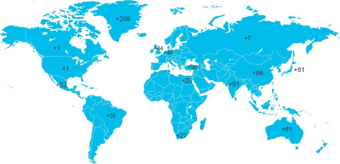
Figure 1-7 World Map Showing the Country Codes from Table 1-4
In today’s networks, it is very common to see E.164 phone numbers applied to endpoints directly or as alternative masks. Service providers often send and accept numbers in the Plus E.164 (+E.164) format, so it might be easier to apply these numbers directly to endpoints than to introduce administrative burden by stripping them down to the subscriber numbers. The following chapters detail how to handle globalized dial plans using E.164 phone numbers and globalized dial plans for both call routing and number presentation.
Case Study: Building a Globalized Dial Plan
Now that you have learned the basics of how phone numbers operate both at a national level for North America and under international E.164 numbering plans, this section walks through a case study to provide an example of an optimized dial plan using the network illustrated in Figure 1-8.
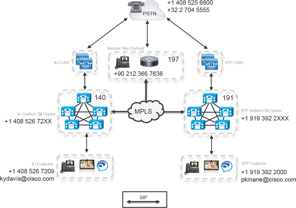
Figure 1-8 A Sample Dial Plan for a Small Enterprise
The topology for this example includes the following major components:
• A San Jose Unified CM cluster with an E.164 DID range of 14085267200 through 14085267299. The X in the number indicates any number 0 through 9.
• An RTP Unified CM cluster with an E.164 DID range of 19193922000 through 19193922999. Again, the X in the number indicates any number 0 through 9.
• Both SJ and RTP use the +1 country code for North America
• There is a remote site in Turkey with a DID range in the +90 country code. For simplicity, only a single directory number (DN) for this remote site is shown.
• All three locations are connected to the PSTN by way of a SIP trunk to CUBE.
• Similarly, all three locations are connected to each other with a SIP trunk over the enterprise MPLS WAN.
• For the sake of illustrating PSTN calling, there are two sample E.164 PSTN numbers here as well.
The following dial plan requirements apply to this case study:
• IP phones within a location should be able to dial other phones using any of the following methods:
• Using the full +E.164 number associated with the phone
• Using an abbreviated four-digit extension to reach other phones within the same site
• Using a private on-net dial plan consisting of the digit 8 followed by a site code and an extension number
• Where possible, calls should not utilize PSTN resources. IP phones that dial phone numbers for on-premises devices should be forced back on-net rather than route to the PSTN, even if they dial the number using a PSTN dialing habit.
• Enterprise IP Phone users should be able to dial local, long-distance, and international phone numbers on the PSTN with the steering code 9.
• PSTN users should be able to call IP phones at any of the enterprise locations.
• The dial plan should provide redundancy. For example, if a CUBE or PSTN connection in SJ goes down, SJ users should still be able to dial PSTN numbers without issue.
• Emergency services calls should be reachable with or without the PSTN steering code.
• On-premises users should be able to call endpoints by using an email address rather than a telephone number, which is a growing trend in the enterprise.
As discussed in Chapter 4, Unified CM provides a variety of dial plan configuration constructs that allow an administrator to design incredibly complex dial plans. These capabilities provide significant flexibility in how a dial plan can be architected. Because of the flexibility, you should understand some best practices of dial plan design.
One important concept is to understand how a globalized dial plan works. As described earlier in this chapter, the E.164 format describes a number in a globally unique form. However, users can dial a number in a variety of different ways: as an abbreviated dial number, as an on-net private call, or as a PSTN call, possibly with leading steering digits and country-specific prefixes. In a globalized dial plan, a number dialed by a user is converted to a global +E.164 format and then routed in its globalized form. When the call is routed to its final destination, the globalized number may be converted to a localized form if, for example, the call is going to the PSTN, where an ITSP is expecting the number in a specific format. Keep this general paradigm in mind as you read through the tasks involved in building a dial plan that meets the requirements.
Task 1: On-Net Calling Between IP Phones
The first decision an administrator designing a dial plan needs to make is how to configure the directory numbers on phone lines. You may be tempted to assign the four-digit extension corresponding to the extension at that site; however, as you will see in Chapter 4, doing this can lead to challenges.
Following best practices, the globalized +E.164 phone number should be configured as the directory number of the line on all endpoints rather than as an abbreviated subscriber number consisting of something like a four-digit extension. The configured number should include the leading plus (+) as part of the number. When users dial a phone number, Unified CM should perform globalization translations to change the dialed number into a globalized format, which will then allow the call to route to the IP phone. The next section describes some of these translations.
Task 2a: Abbreviated Dialing Between Locations
Users may dial 8 and then the site code and finally the last four digits of the directory number for the endpoint they would like to reach. For example, a user in SJ might dial 81912000, which would route the call from the Unified CM in SJ across the SIP trunk/WAN and to the Unified CM in RTP where the phone is registered. This can be achieved in a few ways. One way is to add the abbreviated number as an enterprise alternate number on the line and use dial plan replication, such as ILS, to advertise this alternate number to the other Unified CM clusters. For a less dynamic solution, you can build static call routing elements in Unified CM to take calls with 8 along with the site code and send them to the appropriate SIP trunks and, ultimately, Unified CM. In this scenario, 8191 would always point to the SIP trunk to the RTP CUCM. Alternatively, following the globalized dial plan approach, a translation could be configured to convert numbers that start with 8191 followed by four digits to +1919392 followed by the same four digits.
Task 2b: Abbreviated Dialing Within the Location
It is sometimes desirable to allow users within a site to call each other using an abbreviated number that is locally significant to the site. For example, users in RTP might want to be able to call other phones in RTP by dialing the last four digits of the extension. In this case, a translation could be created that matches 2 followed by three more digits and prefixes +1919392 to the dialed number before attempting to route the call.
Task 2c: Forced On-Net Calling
When a user dials a number using a PSTN dialing habit (that is, dialing 9 followed by the DID of another user instead of using the abbreviated internal dialing methods) and the number really resides on the enterprise network, the call should not be sent to the PSTN, where it would use session capacity, bandwidth, CPU, and memory resources on the network, CUBE, and PSTN. A better method is to intercept the called number and globalize it to the +E.164 number, which is also the phone number applied to the phone. For example, if a user in San Jose dials 919193922000, Unified CM should intercept and convert this number to +19193922000. In keeping with the globalized dial plan approach, you would instruct Unified CM to convert any call that matches 9 followed by 1 and 10 digits to +1 followed by the 10 digits and then attempt to route the call. As you will see in Chapter 4, Unified CM tries to find the best match for this number, and if the resulting number exists as a configured directory number, it is matched directly instead of matching a more generic wildcard pattern that would send the call to the PSTN. Through the use of globalized dial plan replication using ILS, Unified CM in San Jose will know that this number exists on the RTP cluster and routes the call across the SIP trunk/WAN, thus saving PSTN resources for actual PSTN calls.
Task 3: Outbound PSTN Calls
![]()
It is now time to discuss how a user should dial the PSTN in this solution. Each country generally has different dialing habits that describe how to reach a number on the PSTN. In this example, the out-dial steering code 9 is used. What the user dials after the 9 depends on the local dialing habits in the country where the user is located. Table 1-5 details the three different dialing habits used by users on the RTP campus.
Table 1-5 PSTN Call Samples Sourced from RTP Cluster

Table 1-6 shows calls from the perspective of the remote site in Turkey. This shows that the way a user dials a number can vary based on the country. Users in the United States likely dial 9011 to signal an international call, while users in other countries, including Turkey, dial 900.
Table 1-6 PSTN Call Samples Sourced from the Remote Location

In all the scenarios detailed in Table 1-5 and Table 1-6, Unified CM should work to convert the phone number into a globalized +E.164 phone number and remove the steering code and national dialing habit of 9, 9011, or 900. In some cases, such as for the local and 10-digit national dialing habits, the translations must append additional digits that were not dialed by the user. For example, for a local call, the translation must append the local area code to convert the local number to a +E.164 format. Globalizing the number ensures that Unified CM selects the best path for the call, whether it be out to the PSTN or utilizing an on-premises SIP trunk over the WAN after finding the number advertised by ILS. These are only two examples of national dialing habits. (For example, some countries use 000 for international and 00 for national calls.) In any case, the first step is to convert from the national dialing habit to +E.164 format before routing the call.
Task 4: Inbound PSTN Calls
This task is rather trivial because Task 1 did most of the hard work for you. The PSTN should deliver the +E.164 number to CUBE, and if it is not in the correct format, CUBE can be configured to convert the called number to E.164 format before sending the call to Unified CM, or Unified CM can be configured to globalize the number as it is received from CUBE. Because the design stipulates that the directory number on endpoints is in +E.164 format, Unified CM simply routes the call to the endpoint based on the +E.164 number assigned in Task 1.
Task 5: PSTN Dial Plan Redundancy
For outbound redundancy, there are multiple paths to the PSTN. A call from SJ can egress via the local CUBE and PSTN connection or use alternative routing to send the call across the WAN to the RTP Unified CM and leverage the RTP CUBE PSTN resources in the event of a failure. The same can be said of RTP when using the local RTP CUBE PSTN connection first and then failing over to the SJ CUBE PSTN connection as a backup. The remote site could use a different method of redundancy by integrating primary and backup SIP trunks to the same or multiple service providers; in that case, when the first link fails, the second link may be used. This same method of redundancy could be employed on SJ CUBE and RTP CUBE. Furthermore, SJ CUBE and RTP CUBE can be configured with high availability to provide stateful failover of call signaling and media within a high availability pair in the event of a link failure.
Task 6: Emergency Calling
![]()
Many regulations around the world indicate that emergency services should be dialable without a steering code. Therefore, you might need to ensure that particular patterns are callable from all endpoints to ensure that a user trying to call emergency services does not receive a call failure due to dialing the wrong digits. Here are a few examples of possible patterns for the two most common emergency numbers, 911 and 112:
911
9911
112
0112
It is important to ensure that these patterns do not overlap with other parts of your dial plan. For example, you would not want to have an abbreviated dialing number for the extension 9112. Not only would this make accidental calls to 911 likely, you would end up in a situation where either 9112 is not callable because you configure the system to route 911 calls immediately upon detecting those three digits or the system must wait after dialing 911 because it doesn’t know if you are going to dial another digit (2) to reach extension 9112.
Task 7: URI Dialing
It is becoming more common for email addresses to be used in place of or alongside normal telephone numbers; this is known as a uniform resource identifier (URI) dialing, and it is especially useful when using soft clients that allow for user directory searches and click-to-dial. By using the Global Dial Plan Replication feature in Unified CM and URI call routing with CUBE, you can route a call to a URI more easily than ever before. With URI dialing, for example, the Jabber endpoint in SJ may do a quick directory search and find the email address of Patrick in RTP. The user can click once to have the Jabber client initiate a call to the URI [email protected], which the SJ Unified CM will route across the WAN to the RTP cluster and ultimately to Patrick’s Jabber client. URIs can also be used on physical phones; don’t think they are limited just to Jabber, although dialing a URI using a phone keypad can be cumbersome at best.
Closing Remarks
As you can see, by starting with a globalized dial plan with E.164 as the basis, you one can create a dial plan that is scalable, redundant, and easy to manage. Leveraging features such as ILS and Global Dial Plan Replication, you can efficiently route calls on the network and make the best use of limited resources. Chapter 4 dives into how to configure Unified CM with these dial plan and call routing tasks in mind, and Chapter 8 covers how to do the same for IOS XE devices, such as CUBE and Unified CME.
References
Cisco, “Cisco Worldwide Support Contacts,” https://www.cisco.com/c/en/us/support/web/tsd-cisco-worldwide-contacts.html
Cisco, “Preferred Architecture for Cisco Collaboration 12.x Enterprise On-Premises Deployments, CVD,” https://www.cisco.com/c/en/us/td/docs/solutions/CVD/Collaboration/enterprise/12x/120/collbcvd/control.html
Cisco, “Cisco Collaboration System 12.x Solution Reference Network Designs (SRND),” https://www.cisco.com/c/en/us/td/docs/voice_ip_comm/cucm/srnd/collab12/collab12.html
Inamdar, Kaustubh, Steve Holl, Gonzalo Salgueiro, Kyzer Davis, and Chidambaram Arunachalam. Understanding Session Border Controllers: Comprehensive Guide to Designing, Deploying, Troubleshooting, and Maintaining Cisco Unified Border Element (CUBE) Solutions. Hoboken: Cisco Press, 2018.
ITU, “E.164: The international public telecommunication numbering plan,” https://www.itu.int/rec/T-REC-E.164-201011-I
ITU, “E.123: Notation for national and international telephone numbers, e-mail addresses and web addresses,” https://www.itu.int/rec/T-REC-E.123-200102-I
Exam Preparation Tasks
As mentioned in the section “How to Use This Book” in the Introduction, you have a couple of choices for exam preparation: the exercises here, Chapter 11, “Final Preparation,” and the exam simulation questions in the Pearson Test Prep software online.
Review All Key Topics
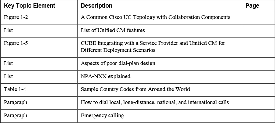
Review the most important topics in the chapter, noted with the key topics icon in the outer margin of the page. Table 1-7 lists these key topics and the page number on which each is found.
![]()
Table 1-7 Key Topics for Chapter 1
Complete Tables and Lists from Memory
Print a copy of Appendix C, “Memory Tables” (found on the companion website), or at least the section for this chapter, and complete the tables and lists from memory. Appendix D, “Memory Tables Answer Key” (also on the companion website) includes completed tables and lists to check your work.
Define Key Terms
Define the following key terms from this chapter and check your answers in the glossary:
numbering plan area (NPA) code
central office exchange (NXX) code