
Chapter 3. VoIP Protocols: RTP, RTCP, and DTMF Relay
This chapter covers the following topics:
• Introduction to Real-Time Media: This section lays the groundwork for how analog voice is digitized and made suitable for transport over an IP network.
• Real-Time Transport Protocol: This section provides an introduction to Real-Time Transport Protocol (RTP) and explains how RTP packets are formatted.
• Real-Time Transport Control Protocol: This section covers Real-Time Transport Control Protocol (RTCP) as a peer protocol to RTP and discusses various RTCP packet types.
• DTMF Relay: This section provides a brief introduction to DTMF relay and provides details about the various methods of DTMF relay used in real-time communication networks.
This chapter covers the following CLACCM 300-815 exam topics:
• 1.2 Troubleshoot these H.323 protocol elements
• 1.2.a DTMF
• 1.3 Troubleshoot media establishment
• 3.1 Configure these Cisco Unified Border Element dial plan elements
• 3.1.a DTMF
• 3.2 Troubleshoot these Cisco Unified Border Element dial plan elements
• 3.2.a DTMF
The transmission of real-time voice and video over an IP network is complex and requires a comprehensive framework of protocols to ensure proper operation and a good user experience. Real-Time Transport Protocol (RTP) and its complement Real-Time Transport Control Protocol (RTCP) are foundational components of this framework. These protocols and their extensions have seen industrywide adoption as the basis of IP-based real-time communications.
The transmission of voice and video media streams is an important aspect of media handling on IP networks, but there are other elements to consider. For example, relaying dual-tone multifrequency (DTMF) across an IP network is vital for call routing and also for navigating interactive voice response (IVR) menus. The advent of voice over IP (VoIP) made reliable and distortion-free transmission of keypad button presses end-to-end somewhat problematic because audio codecs were not optimized for carrying DTMF tones. Fortunately, the industry (led by the IETF and ITU-T) came up with and standardized several methods of DTMF relay that have worked remarkably well. This chapter analyzes these different media plane protocols and operations, including how voice and video are transported over an IP network using RTP/RTCP. This chapter also provides an introduction to the various common methods of DTMF relay available today.
“Do I Know This Already?” Quiz
The “Do I Know This Already?” quiz allows you to assess whether you should read the entire chapter. If you miss no more than one of these self-assessment questions, you might want to move ahead to the “Exam Preparation Tasks” section of the chapter. Table 3-1 lists the major headings in this chapter and the “Do I Know This Already?” quiz questions related to the material in each of those sections to help you assess your knowledge of these specific areas. The answers to the “Do I Know This Already?” quiz appear in Appendix A, “Answers to the ‘Do I Know This Already?’ Quiz Questions.”
Table 3-1 “Do I Know This Already?” Foundation Topics Section-to-Question Mapping
1. What is the sampling rate of the G.711 audio codec?
a. 8 kHz
b. 64 kHz
c. 8000 kHz
d. 64,000 kHz
2. Which payload types fall within the dynamic range for RTP? (Choose three.)
a. 0
b. 18
c. 96
d. 114
e. 127
f. 151
3. Which RTP packet header is responsible for assisting receiver applications with loss detection?
a. SSRC
b. Timestamp
c. Marker Bit
d. Sequence Number
4. In which scenario might the SSRC value for a given RTP stream change?
a. When a rollover of the RTP Sequence Number field occurs
b. When the Marker Bit field is set to False
c. When the RTP transport address changes
d. Every 15 minutes
5. What is the recommended amount of bandwidth allocated to RTCP?
a. 5%
b. 15%
c. 25%
d. 50%
6. Which two SDP attributes are commonly used for signaling RTCP port information that will be used for a stream? (Choose two.)
a. a=rtcp
b. a=rtcp-mux
c. a=rtpmap
d. m=
e. c=
7. Which type of DTMF relay method is carried within RTP packets as a specialized payload?
a. SIP KPML
b. Name telephony events
c. SIP INFO
d. SIP NOTIFY
8. Which of the following are possible payload types for RTP-NTE DTMF? (Choose two.)
a. 0
b. 8
c. 18
d. 99
e. 101
9. While attempting to establish a new call, which SIP message contains the first digit dialed by a user of a SIP Cisco IP phone using SIP KPML to send digits to Unified CM?
a. INVITE
b. SUBSCRIBE
c. NOTIFY
d. 200 OK
10. When troubleshooting out-of-band DTMF issues, where should an administrator focus his or her efforts?
a. The RTP media packets
b. The RTP-NTE packets
c. The call setup signaling
d. The firewall
Foundation Topics
Introduction to Real-Time Media
The ability to communicate in real time over an IP network was a major advancement and is the foundation for voice over IP technologies. Communication over an IP network requires a mechanism to transform the analog voice signal from a telephone into a digital format. Interestingly, this analog-to-digital conversion of voice has been around for a long time and is also the basis for phone calls placed over the traditional public switched telephone network (PSTN). Obviously, one key difference between a voice call made on the PSTN and a voice call placed over an IP network is that once the analog voice signal is converted to a digital signal, it must also be encapsulated in the proper IP/UDP headers so that it is in a format that is suitable for transport over the IP network infrastructure.
Consider this scenario: Alice wants to place a phone call to Bob across an IP network. Alice will speak into a telephone, and that audio needs to be properly heard by Bob on the other side of the network. For this to be a bidirectional conversation, the reverse also needs to be true. Bob will also speak into the telephone in response to Alice, and she, in turn, must be able to properly hear Bob’s speech. In this scenario, there are two independent media streams:
• Alice to Bob
• Bob to Alice
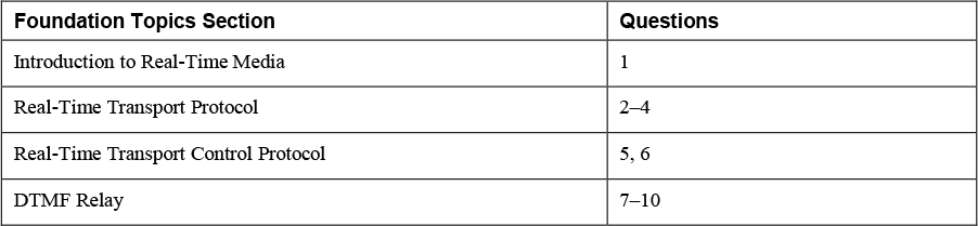
So how are these media streams transported over the IP network? The answer to this question is quite complex and has several moving parts. Alice is speaking into a telephone, an analog device, so there needs to be an analog-to-digital conversion, and that digital signal then needs to be encapsulated properly so that it can be carried and routed across the IP network. This analog-to-digital conversion is depicted in Figure 3-1 and involves either three or four major steps:
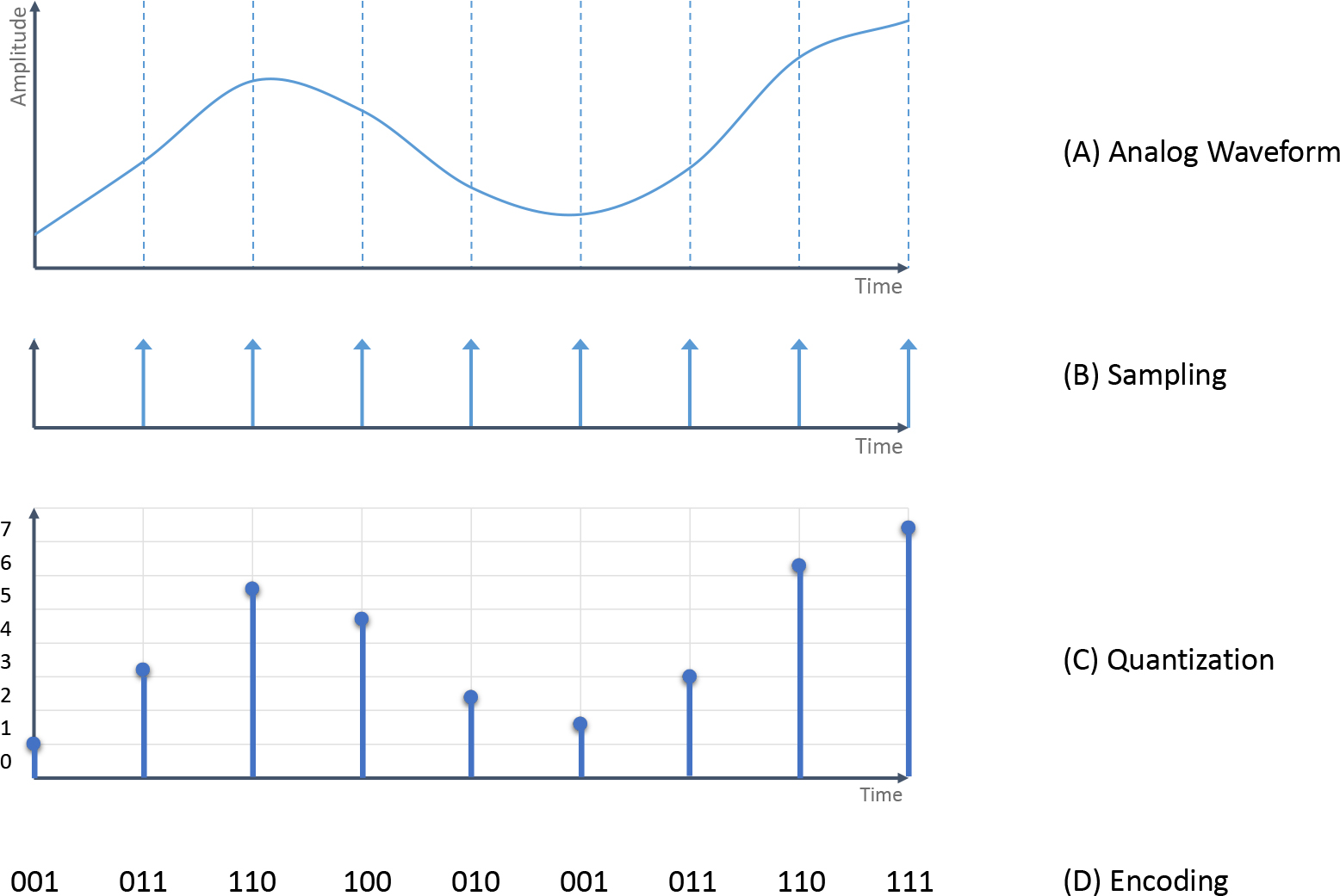
Figure 3-1 Analog-to-Digital Conversion
![]()
Step 1. Sampling: The continuous analog voice signal shown in part A in Figure 3-1 is reduced to many discrete readings by taking frequent recordings, or samples, at regular time intervals, as shown in part B in Figure 3-1. The sampling rate varies depending on the codec being used. For example, if G.711 is the codec being used, the analog voice signal will be sampled at 8 kHz, or 8000 times per second. As Figure 3-2 demonstrates, the sampling rate greatly impacts the audio quality because it directly determines how accurately the original analog signal is reproduced (fidelity). Unsurprisingly, sampling rate has a classic trade-off whereby the higher the sampling rate, the better the fidelity—but at the expense of increasing data rates. According to Nyquist’s theorem, if a signal is sampled at a rate that is twice the highest frequency of the signal, it provides enough samples to accurately reconstruct the original signal. Since the majority of normal human speech occurs at a frequency less than 4 kHz, a sampling rate of 8 kHz is commonly used to reproduce that speech with acceptable fidelity, in accordance with Nyquist’s theorem.
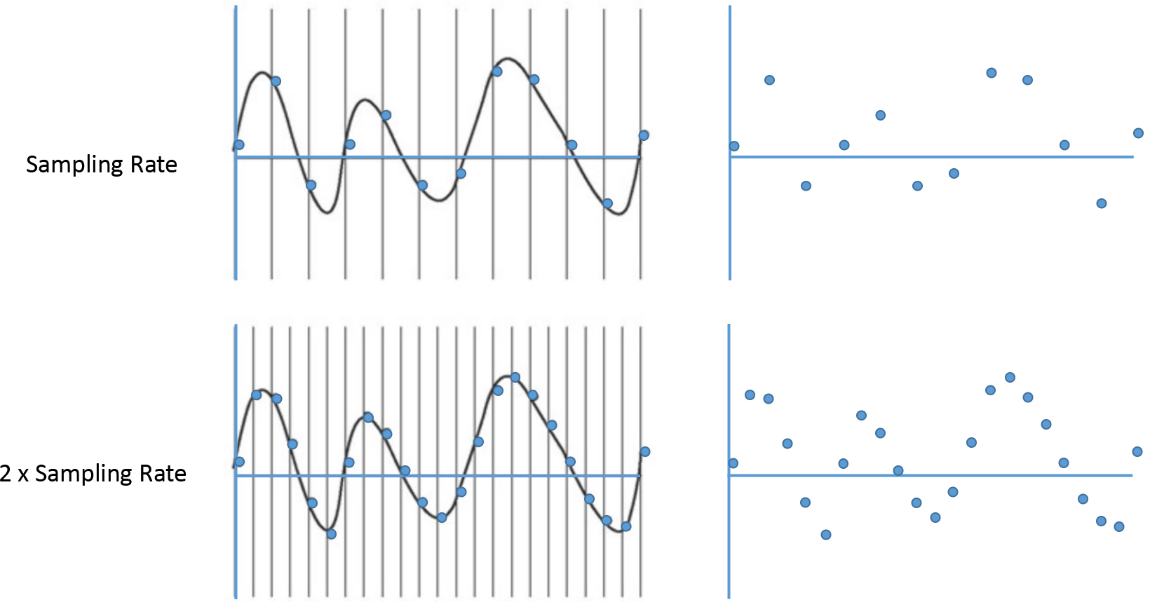
Figure 3-2 The Effect of Doubling the Sampling Rate
Step 2. Quantization: After sampling the original analog signal in part A of Figure 3-1, the resultant audio samples are quantized so their amplitudes have discrete numeric values assigned. This means that the signal range of human speech is divided into a certain number of intervals, as shown in part C of Figure 3-1. The more intervals used to subdivide the spectrum, the more accurate the readings can be, compared to the original analog waveform. Increased accuracy means the rounding errors are fewer and smaller, which consequently means less noise is introduced relative to the signal.
Step 3. Encoding: The different quantized values need to be encoded with a digital representation (that is, some number of bits). The number of bits used for encoding depends entirely on the quantization. For example, in part D of Figure 3-1, there are eight different quantization levels, and this can be represented digitally with just 3 bits, as shown. It stands to reason that more intervals require more bits to encode. So, once again, the trade-off is between bandwidth consumption and audio quality. Different codecs use different quantizations, and their audio quality is directly related to this. For example, the standard G.711 codec uses 8 bits per sample for quantization (256 levels), whereas the higher-quality (and higher-bandwidth) wideband G.722 codec uses 14 bits per sample for quantization (16,384 levels).
Step 4. Compression (optional): The encoded audio samples can be optionally compressed using a variety of algorithms. Different codecs use different compression techniques to save bandwidth. The effects these compression techniques have on audio quality vary greatly based on the type of audio, network conditions, compute availability, and so on.
Figure 3-3 shows the end-to-end voice conversation between Alice and Bob. Alice and Bob are both using Cisco IP phones that contain built-in digital signal processors (DSPs). A DSP is responsible for the analog-to-digital conversion described here (that is, sampling, quantizing, encoding, and compression). The encoded digital audio samples need to be properly encapsulated with IP/UDP headers so they can be properly transported and routed across an IP network infrastructure. The remote IP phone needs to go through the opposite process in order for Bob to hear Alice. This means the IP phone needs to de-encapsulate the digital signal from the received packets. Then the DSP on the far end IP phone performs a digital-to-analog conversion and plays back a reconstruction of Alice’s original analog signal out to Bob.
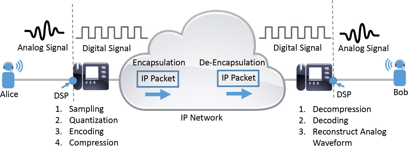
Figure 3-3 End-to-End Voice Call Across an IP Network
This same process of analog-to-digital conversion and encapsulation followed by de-encapsulation and digital-to-analog conversion happens when Bob responds to Alice. These are two different and independent real-time media streams. What isn’t clear yet is the details of how the inherently real-time properties of these original voice signals are captured and maintained across a network that could introduce all sorts of impairments, such as packet loss, delay, and jitter. This is where Real-Time Transport Protocol comes in.
Real-Time Transport Protocol
Real-Time Transport Protocol (RTP), originally defined in RFC 1889 and superseded by RFC 3550, provides a framework for the end-to-end transport of voice and video. RTP typically operates over UDP/IP and provides built-in loss detection, receiver feedback, source identification, important event indications, and sequencing. RTP has a peer protocol, Real-Time Control Protocol (RTCP), that provides media reception feedback for the related RTP stream. RTCP is discussed in further detail in the following section.
Central to the operation of RTP is the concept of an RTP session. An RTP session is a group of participants interacting over RTP, such that a given participant may be a part of several different RTP sessions at the same time. For example, a pair of endpoints could have both an audio RTP session and a video RTP session active between them. An RTP session is identified by the combination of a network address and port pair on which traffic is sent and received. Different ports may be used for RTP and RTCP for each session, or both protocols may be multiplexed over a common UDP port.
An RTP session can be either unicast (one-to-one communication between a pair of participants) or multicast (one-to-many communication to participants). Before exploring various other topics discussed in this and subsequent chapters, it is important to first take a close look at the RTP packet format.
An RTP packet consists of two parts: an RTP header and an RTP payload (with optional padding). Figure 3-4 shows the RTP packet format.
![]()

Figure 3-4 RTP Packet Format
The RTP header includes the following fields:
• Version (V): This header field specifies the RTP version in use. The current version at the time of this publication is 2.
• Padding (P): This single-bit header field, when set to 1, indicates that there are additional octets appended to the RTP payload. These additional octets are not part of the payload and are primarily inserted to ensure that certain encryption algorithms always work on fixed-size blocks of data.
• Extension (X): This single-bit field indicates the presence of an RTP header extension. RTP header extensions are required to carry additional media session information that cannot be encoded within the standard RTP headers or payload. Typical examples of this include the RTP header extensions for audio-level information on RTP samples, as defined in RFC 6464. Although header extensions are not commonly implemented, it is important for the specification to provide accommodation for these rare cases.
• CSRC Count (CC): This field identifies the number of CSRC identifiers that follow the fixed header field. CSRCs are explained further later in this section.
• Marker Bit (M): This header field is used to designate important events during the media session. For example, the marker bit might designate the start of a new DTMF event. This usage can be observed when using named telephony events for DTMF transmission. Yet another usage of the M field is when the payload format changes during a media session. For example, a media session might negotiate G.711 as the audio codec and begin transmission of RTP packets back and forth. Sometime during the course of the communication session, an application interaction might cause the audio codec to change to G.729 (a change that is accompanied by a corresponding Session Description Protocol [SDP] offer/answer exchange), and the first RTP packet encoded with a G.729 payload has the marker bit set. Setting of the marker bit indicates the occurrence of a significant event (such as a transition from G.711 to G.729) from the perspective of the media stream.
![]()
• Payload Type (PT): This field indicates how the RTP packet should be handled and interpreted at the receiver. Payload Type values are correlated to specific payload formats (for example, PCMU, G.729, H.264) through the use of RTP profiles. From the perspective of SIP, this correlation is carried within the SDP body of the offer/answer exchange. Consider Example 3-1, which demonstrates the SDP body of a typical SIP INVITE request.
Example 3-1 SDP Body Demonstrating the Correlation Between the Payload Type, Payload Format, and RTP Profile
INVITE sip:[email protected]:5060 SIP/2.0
Via: SIP/2.0/UDP 192.0.2.2:5060;branch=z9hG4bK531305
From: <sip:[email protected]>;
To: <sip:[email protected]>;tag=53A7B00-628
Call-ID: [email protected]
[..Omitted for brevity..]
Content-Type: application/sdp
Content-Length: 221

v=0
o=CiscoSystemsSIP-GW-UserAgent 7031 5812 IN IP4 192.0.2.2
s=SIP Call
c=IN IP4 192.0.2.2
t=0 0
m=audio 16512 RTP/AVP 0
c=IN IP4 192.0.2.61
a=rtpmap:0 PCMU/8000
a=ptime:20
In Example 3-1, the payload type advertised is 0, the RTP profile is RTP/AVP, and the rtpmap attribute provides a mapping between the payload type (0) and the payload format (G.711μ). The RTP/AVP profile (audio/video profile), defined in RFC 3551, is the most commonly used profile; it defines several static assignments of payload types to payload formats. Table 3-2 lists some of these well-known static assignments.
Table 3-2 Payload Type-to-Format Mapping for RTP/AVP
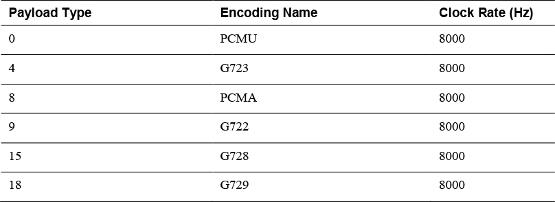
The RTP profile is also useful in providing the clock rate for predefined static assignments. The payload formats are responsible for determining how information is encapsulated in the RTP packet, such as specifying what is present in the RTP header and the RTP payload.
![]()
• Sequence Number: This 16-bit field increases sequentially for each RTP packet sent from the sender to the receiver. It is through this 16-bit field that RTP provides its built-in loss-detection mechanism. Packets are assumed to have been dropped during transit if the receiver notices a break in the RTP sequence numbers of received packets. Figure 3-5 depicts a scenario in which the receiver experiences packet loss in a real-time communication session.
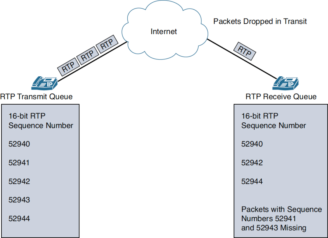
Figure 3-5 RTP Packet Loss During a Real-Time Communication Session
The RTP sequence number is always chosen randomly and does not start from zero. From the randomly chosen offset of the first RTP packet, successive RTP packets have incrementally increasing sequence numbers. A random sequence number value is usually chosen for the initial RTP packet to protect against known plaintext security attacks.
Note
A common misconception about the Sequence Number field is that it assists the receiver in determining the order in which the packets are played out, but this is an incorrect assumption. The order in which packets are played out at the receiver is dependent on the RTP Timestamp header field, described next. The Sequence Number field simply assists the receiver with loss detection.
• Timestamp: The Timestamp header field is a 32-bit value that designates the sampling instant of the first octet of the media payload in the RTP packet. The sampling instant is derived from a media clock that increases linearly and monotonically in time. The rate at which this clock advances is dependent on the payload format and can sometimes drastically vary based on the media format. The timestamp field is used at the receiver to decide the order in which packets are played out. The timestamp header field value in the first packet is randomly chosen and advances at a rate specified by the payload format (refer to Table 3-2).
![]()
• Synchronization Source (SSRC) Identifier: This 32-bit field serves as an identifier of a participant in an RTP session. The SSRC values must always be chosen randomly by participants in an RTP session because each RTP session has its own unique SSRC space. If one or more participants in an RTP session have the same SSRC value (which is possible because these values are chosen randomly), a collision occurs. Collisions are resolved by having the endpoints send an RTCP BYE packet, followed by choosing a new random SSRC value. For participants that are part of multiple RTP sessions at the same time (for example, both an audio session and a video session), the SSRC values have to be unique across those multiple sessions. Some of the scenarios that might cause the SSRC to change during the course of a communication session include the following:
• Application restarts
• SSRC collisions
• Changes in the RTP transport address (network address and port pair)
• Contributing Source (CSRC) Identifier: There are often scenarios in real-time communication sessions in which participants stream media directly to an intermediary device such as a mixer. The mixer is responsible for combining streams from various participants and sending over the resultant media stream to one or more receivers. Because the mixer is part of the RTP session, it has its own SSRC value that is used when it transmits RTP packets. The number of sources that contribute to the resultant output of the mixer is captured in the CC field of the RTP packet. The individual SSRCs of the contributing sources are captured in the CSRC blocks. Note that not all RTP packets contain this header field, as it is only used when combining streams from various sources. This forms a part of the optional RTP header.
• Payload Header: The presence of this optional header is based on the requirements of the payload format that is negotiated.
• Media Payload: This forms the actual media data that is framed by the RTP packet. Its contents are governed by the payload format that is used.
When an application builds an RTP packet and places it on the wire for transport, it utilizes UDP as the transport layer protocol. The “fire and forget” nature of UDP is perfect for multimedia application data such as RTP because of the reduced overhead afforded by removing packet acknowledgements. As mentioned earlier, a real-time application uses the RTP sequence number to determine whether packet loss has occurred, but the reality is that it does not request that a missing packet be re-sent. The real-time nature of the RTP media stream implies that it is of no use to the applications and users to receive out of order audio samples that were previously missed. To further illustrate the point, imagine a scenario in which you are listening to an RTP stream and the phrase “Hello, how are you today?” is mentioned and encoded in RTP packets and sent across the network. In this theoretical example, the RTP stream containing the word (or part of the word) “how” is dropped along the transit path. Would the receiver of this audio stream ever want to hear this missed audio sample later, via retransmission of the packet from the sender to the receiver? The answer is clearly no. In fact, the conversation likely continued on without the need for retransmission and often, due to a variety of audio quality mitigation techniques, without a perceptible impact to the conversation.
As per RFC 3550, RTP applications should use an even UDP port number for RTP. It should also be noted that RFC 3550 does not define any default range of UDP ports that can be used by RTP. A common misconception is that RTP can only use the even UDP ports ranging from 16384 through 32767. While this is considered the “unspoken” standard UDP port range for RTP, in the real world, many service provider devices, third-party devices, and even Cisco products utilize nonstandard or extended UDP port ranges for RTP. For example, Cisco Unified Border Element (CUBE) on IOS XE uses RTP ports 8000 through 48198, and Cisco Expressway uses ports 36000 through 59998. Administrators should review applicable documents on RTP port ranges when configuring access control lists (ACLs) and firewall rules. Furthermore, many devices offer configurable RTP port ranges, including Unified CM and CUBE. Thus, in the event of preexisting implementations, you should check active configurations to verify the RTP port range in use.
Note
Contrary to popular belief, RTP can be sent over TCP. RFC 4571 serves as the basis for using RTP and RTCP over connection-oriented transports such as TCP. Although it is unlikely that you will find it in most deployments, Cisco Webex may attempt to utilize TCP as a backup transport protocol in the event that UDP is blocked on the enterprise. The use of TCP as the transport for RTP is signaled through the SDP with the m= line containing TCP/RTP/AVP rather than the standard RTP/AVP used with UDP RTP.
Real-time networks transmit voice and video data over RTP such that each individual RTP packet contains a fixed-size payload that serves as an information unit. Within the RTP payload are the voice and video samples that are encoded and decoded at the sender and receiver applications, respectively. The time duration of media that is encoded within these payloads, known as the packetization period, can vary on a per-codec basis. For example, G.711-encoded streams can have packetization periods that vary from 5 milliseconds to 40 milliseconds.
Table 1 in RFC 3551 highlights the default packetization periods to be used by RTP-based applications for a myriad of codecs. Table 3-3 provides a few selected examples.
Table 3-3 Default Packetization Periods of Common Audio Codecs
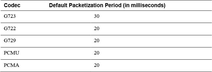
Consider that every RTP packet sent requires a predefined amount of (IP/UDP/RTP) header data. As a result, more packets sent per second results in more header data being sent, amounting to higher consumption of bandwidth. As a result, increasing the packetization period may be desirable to reduce the amount of bandwidth from the resulting IP/UDP/RTP header, thus increasing the overall real-time voice or video data throughput. This could be very useful over bandwidth-limited or expensive WAN links. For example, a 20 ms packetization period for G.711ulaw means that there are 160 bytes of audio payload data carried within the RTP packet. On the other hand, a 30 ms packetization period for the same audio codec would contain 240 bytes of payload data. Recall from the previous section that audio is sampled when it is digitized. This means that the packetization period values directly influence how many packets per second (pps) are sent on the network. For G.711ulaw with a 20 ms packetization period, there will be 50 pps (8000 / 160). These types of calculations are useful when performing bandwidth checks and configuring quality of service on a network.
RTP sessions are subject to fixed and variable delays in packet transmission. The default packetization periods for different codecs merely serve as recommendations and can be overridden when needed. The process of changing the effective bit rate by manipulating the packetization periods, known as transrating, can increase or decrease the packetization delay, depending on the amount of voice and video data encoded in RTP packet payloads. With transrating, the only factor directly influenced is the packetization delay, which is the amount of time taken to encode the payload of the RTP packet. Transrating introduces some trade-offs, with advantages and disadvantages that need to be considered on a case-by-case basis:
• Increasing the packetization period (and hence the packetization delay) results in packets with large media payloads but decreases the overall number of packets that traverse the network. A risk of increased packetization times is the increased latency required for the sampling of audio and an increased loss of audio content during packet loss, which results in a decrease in the ability to conceal the packet loss effect to the listener.
• Decreasing the packetization period means the media payloads are smaller, resulting in the packets being placed on the network much sooner and decreasing the likelihood of voice quality issues. The downside to this is the unnecessary and costly increase in overall bandwidth utilization. A decrease in the packetization period has no effect on the size of the RTP/UDP/IP headers, as packetization operations are specific to RTP payloads.
![]()
In RTP sessions that are set up using SIP and SDP, the packetization period is advertised using the ptime and maxptime attributes. The ptime attribute specifies the length of media within a packet, expressed in milliseconds, whereas the maxptime attribute specifies the maximum amount of media that can be encapsulated in a packet, also expressed in milliseconds. While setting up a communication session between RTP peers, in the ensuing offer/answer exchange, if the ptime attribute is included in the SDP body by the offeror or answerer, it indicates the desired packetization interval that the offeror or answerer would expect to receive. Example 3-2 highlights the use of the ptime attribute in SDP.
Example 3-2 Using the SDP ptime Attribute to Indicate the Desired Packetization Interval
INVITE sip:[email protected]:5060 SIP/2.0
Via: SIP/2.0/UDP 192.0.2.2:5060;branch=z9hG4bK531305
Remote-Party-ID: <sip:[email protected]>;party=calling;screen=no;privacy=off
From: <sip:[email protected]>;
To: <sip:[email protected]>;tag=53A7B00-628
Date: Sat, 04 Feb 2017 07:11:33 GMT
Call-ID: [email protected]
[..Omitted for brevity..]
Content-Type: application/sdp
Content-Length: 221

v=0
o=CiscoSystemsSIP-GW-UserAgent 7031 5812 IN IP4 192.0.2.2
s=SIP Call
c=IN IP4 192.0.2.2
t=0 0
m=audio 16512 RTP/AVP 0
c=IN IP4 192.0.2.61
a=rtpmap:0 PCMU/8000
a=ptime:20
The ptime (or maxptime) attribute is encoded in SDP using the following format:
a=ptime:<packet time>
a=maxptime:<maximum packet time>
The numeric value specified in the attribute denotes the value, in milliseconds, of the desired packetization time or maximum possible packetization time, depending on whether the ptime or maxptime attribute is used. If the ptime attribute is not specified in the SDP, the default packetization period for the codec applies. (Refer to Table 3-3 for a selected representation and Table 1 in RFC 3551 for further details.)
The use of these two SDP attributes is entirely optional, and not all media codecs make use of them. If you have a packet capture containing RTP packet, you can surmise the ptime value for a given stream by performing the following steps with Wireshark:
Step 1. Ensure that RTP packets are decoded by default by navigating to Analyze > Enable Protocols > RTP and then enabling the rtp_udp checkbox and clicking OK. The Wireshark dissector then decodes the packets even when there is no accompanying call signaling.
Step 2. Filter the packet capture down to a single RTP stream. This can be done with a few Wireshark filters by either determining the UDP source or destination port or the SSRC of the RTP stream of interest. Using Figure 3-6 as an example, you could create three different Wireshark filters to filter the packet capture to a single stream. These example filters are as follows, with the rtp.ssrc filter being applied in Figure 3-6:
udp.srcport == 8452
udp.dstport == 24812
rtp.ssrc == 0x00007a4a

Figure 3-6 Wireshark ptime Example
Step 3. When a single RTP stream has been filtered, navigate to View > Time Display Format and select Seconds Since Previous Displayed Packet. Wireshark now takes into account displayed packets using the filter of choice from step 2. You can now observe the calculated time between packets. With audio codecs that utilize linear packetization, such as those observed in Figure 3-6, you should see a ptime that matches the payload size of the packet. This type of filter and display format can also be useful for determining areas of large delay and jitter within a given RTP stream.
Real-Time Transport Control Protocol
As discussed in the previous section, RTP defines a framework for real-time transfer of audio and video media between senders and receivers in an RTP session. The RTP framework also defines a peer protocol called Real-Time Transport Control Protocol (RTCP) that includes the following functions:
• It allows receivers to provide periodic reception quality feedback to senders by using receiver reports. These reports enable senders to take stock of network characteristics and possibly alter their transmission patterns, as required.
• RTCP defines a transport-level identifier called the canonical name (CNAME) that serves as the common identifier for all media streams transmitted by a source. This is especially useful in cases in which a source changes its SSRC during a communication session or when a source transmits multiple streams simultaneously. It also assists the receiver in correlating multiple streams to a given participant and in achieving media synchronization across the multiple streams transmitted by the participant.
• RTCP requires all participants to exchange reports, regardless of whether they are active senders. This ensures that there is a global view of the RTP session. RTCP provides useful diagnostics and gives each participant an estimate of the number of members in the RTP session.
• RTCP can optionally be used to transmit additional information in terms of participant identity, email, and location information.
Given that all participants must stream RTCP traffic, transmission must be periodic and designed in such a way that it does not overrun session bandwidth. This is especially true for RTP sessions that have a large number of participants; if RTCP traffic were to be exchanged at the same rate as RTP, there would be bandwidth contention and a potential for lost data. As a result, RTCP traffic must always be allocated a fraction or percentage of total session bandwidth. The recommended percentage of bandwidth allocation for RTCP is 5%, with active senders allocated one-quarter of the total RTCP bandwidth. This ensures that required reports, such as those for media synchronization, are successfully delivered in a timely manner, without competing against RTP for bandwidth.
RTCP defines many different packet types that are used for different scenarios. This chapter covers five of the most common RTCP types observed in Cisco Unified Communication environments. All the RTCP packet types use the common format shown in Figure 3-7.

Figure 3-7 Common RTCP Packet Format
The following fields are included in the common RTCP packet format:
• Version (V): Specifies the version number, which correlates to the version of RTP, currently 2.
• Padding (P): When set, this bit indicates that the packet contains additional data octets toward the end of the packet. This is primarily required when encryption ciphers require fixed-size blocks of data.
• Receiver Count/Source Count (RC/SC): This header field is used to provide the count of receiver reports or source description (SDES) items included in the RTCP packet.
• Packet Type (PT): The encoding in this header field defines the RTCP type. Different RTCP packet types are described in the next section.
• Length: This header field denotes the length of the packet following the common header. This field is expressed in 32-bit words and can have a value of 0. A value of 0 indicates an empty packet that just contains the 4-byte common header.
All RTCP packets must be sent as compound RTCP packets, which include a combination of different RTCP packet types that follow a very strict ordering scheme. The next few sections describe five different RTCP packet types, which serve different purposes in a communication session:
• RTCP sender report (SR)
• RTCP receiver report (RR)
• RTCP source description (SDES)
• RTCP goodbye (BYE)
• RTCP application-defined packet (APP)
RTCP Sender Report (SR)
Figure 3-8 shows an RTCP SR, which primarily assists in media stream synchronization, and, when used in combination with the SDES packet type, also assists receivers in correlating media streams to a particular source.
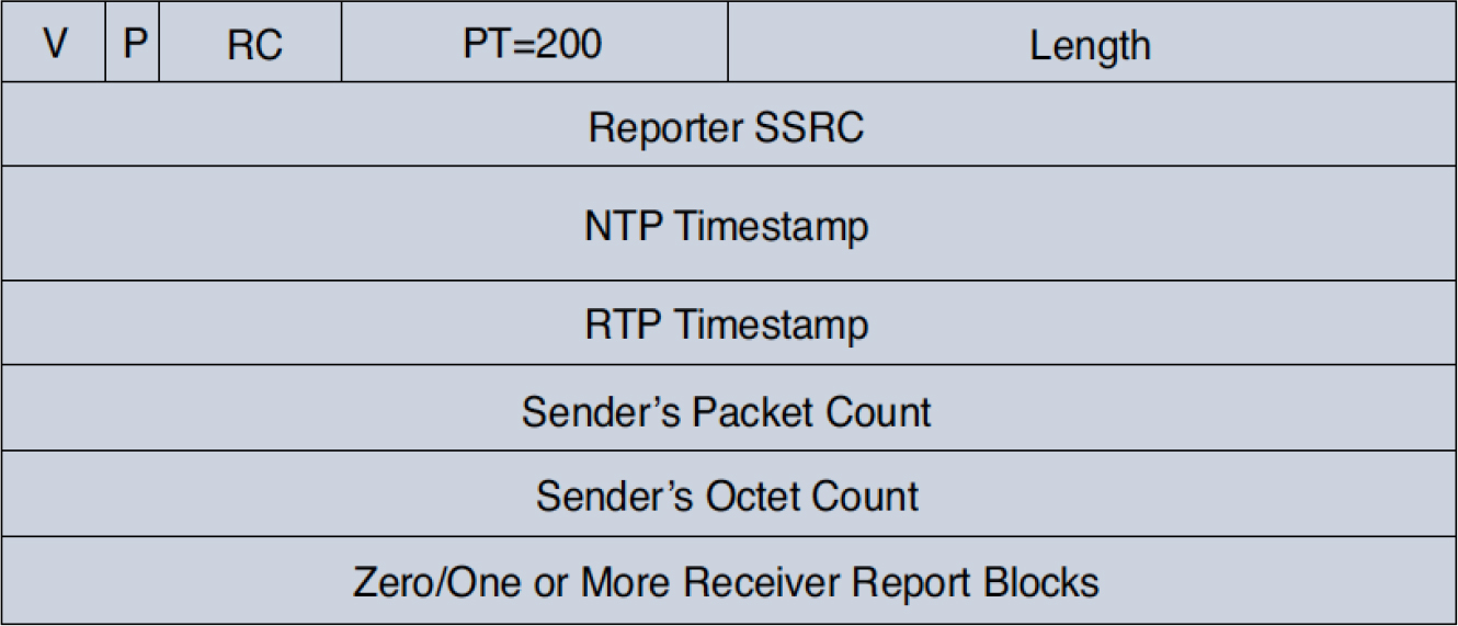
Figure 3-8 RTCP Sender Report Format
RTCP sender reports are sent by sources that have recently transmitted media and are identified by a packet type value of 200. An active sender also includes reception statistics for all the other sources from which it has received media packets. The reception statistics are encoded as RTCP receiver report (RR) blocks, such that each block corresponds to a source from which media was received.
The Receiver Count (RC) header field in the RTCP sender report packet captures the number of receiver report blocks included. If media hasn’t been received from any source, there are no receiver report blocks included in the compound RTCP packet, and the RC header field is set to 0.
The Reporter SSRC field of the packet sender encodes the SSRC of the source that transmits the RTCP SR packet, and it is a 32-bit field. Following this is a 64-bit Network Time Protocol (NTP) Timestamp field. The time in this field is expressed in NTP format, which is the number of seconds that have elapsed since January 1, 1900. This field indicates the time when the RTCP SR packet was sent.
The 32-bit RTP Timestamp header field encodes the same time as the NTP Timestamp header field but is expressed in RTP timestamp format. The receiver uses the NTP Timestamp and RTP Timestamp header fields to synchronize the media clocks of the different streams from a sender, allowing for synchronization of offset audio and video media streams (lip sync).
Following the RTP Timestamp field are the Sender’s Packet Count and the Sender’s Octet Count fields. The Sender’s Packet Count field captures the total number of RTP data packets transmitted by the sender from the start of the session up through transmission of the RTCP SR packet. The Sender’s Octet Count field captures the total number of data octets sent since the start of the RTP session, up through transmission of the RTCP SR packet. The octet count does not take into account the RTP headers and padding and is only concerned with the number of octets that are sent using the RTP packet payload.
Note
The Sender’s Packet Count and the Sender’s Octet Count field values are reset if the SSRC changes for a sender during the RTP session. SSRC values can change if there is an SSRC collision detected or if the sender changes its media type during an RTP session.
Sender reports can also be used to get an estimate of the average payload size of RTP data packets transmitted by a sender and the network throughput available.
RTCP Receiver Report (RR)
RTCP receiver reports are used to report transmission statistics to the senders from which RTP media packets are received. The format of an RTCP receiver report is illustrated in Figure 3-9. The Packet Type header field in an RTCP RR packet is set to 201, and the number of reports blocks present in a particular RTCP RR is captured in the RC header field.

Figure 3-9 RTCP Receiver Report Format
The identity of the sender of an RTCP RR packet is captured by using the SSRC of Sender header field. The RTP sender for which statistics are being reported is indicated by the SSRC of Source_N header field. It is possible for a single participant in an RTP session to receive RTP packets from multiple sources, in which case reception statistics have to be reported for each source. A total of 31 reception reports are possible per RTCP RR packet. If there are more than 31 sources to report on, multiple RTCP RR compound packets must be leveraged.
The Loss Fraction header field captures the fraction of RTP media packets lost from a particular source since the transmission of the previous SR or RR packet. This value is expressed as a fixed-point number, with the binary point at the left edge of the field. The fraction is calculated by dividing the number of packets lost by the number of packets expected. During an RTP session, it is not uncommon to come across packet duplicates, in which case the number of packets received would be more than the number of packets actually expected. This results in the number of packets lost (described next) being represented as a negative value. In such scenarios, the Loss Fraction header field is set to 0.
The Cumulative Number of Packets Lost header field is a 24-bit signed integer that denotes the number of packets received subtracted from the number of packets expected. The number of packets expected is defined as the extended last sequence number received subtracted from the initial sequence number received. In the case of packet duplicates, the Cumulative Number of Packets Lost header field carries a negative value.
Extended Highest Sequence Number Received is a 32-bit header field value, where the lower 16 bits indicate the highest sequence number received in an RTP media packet from a given source. The higher 16 bits indicate the number of times the sequence numbering in RTP media has wrapped around from 65535 (maximum value) to 0 (minimum value).
Note
The sequence number in RTP packets is a 16-bit field, which means RTP packets from a source can carry distinct sequence numbers for a maximum of 65,535 packets (216 packets). After crossing this maximum value, the sequence number has to wrap around to 0. Wrapping of RTP sequence numbers is fairly common and occurs for conversations that extend a duration beyond 21 minutes 50 seconds (assuming a codec packetization rate of 50 packets per second). It is for this reason that sequence numbers cannot be used to uniquely identify packets within an RTP session. To account for this, a 32-bit sequence number is commonly used, where the lower 16 bits encode the RTP sequence number of a packet, and the upper 16 bits encode the number of times the sequence number space has wrapped around to 0.
The Interarrival Jitter field provides an estimate of the statistical variance of the RTP media packet interarrival time. This header field is measured in timestamp units and expressed as a signed integer.
The Last SR (LSR) header field captures the middle 32 of the 64 bits received in the NTP Timestamp header field of the previous SR packet to which this RR block corresponds. If there haven’t been any RTCP SR packets received from the source, this field is set to 0.
The Delay Since Last SR (DSLR) header field is a 32-bit field expressed in units of 1/65536 seconds that calculates the delay between receiving the last SR packet from a source (to which this RR block corresponds) and sending this RR block. If no SR packet has been received yet from the corresponding source, this header field is set to 0.
RTCP receiver reports are commonly used to provide reception quality feedback to senders in real time. Senders can use these reports to alter their transmission patterns. In addition, third-party monitoring applications use RTCP reports to gauge the overall media quality of sessions from local, regional, or global perspectives.
RTCP Source Description (SDES) Packet
The RTCP SDES packet is primarily used to provide a persistent participant identifier that spans SSRC changes and system restarts. In addition to providing a persistent identifier, it also provides information such as the participant name, email address, location, and telephone number. The common SDES packet format, illustrated in Figure 3-10, carries the packet type 202. SDES packets contain zero or more chunks, and the exact count of chunks is captured in the SC header field value.
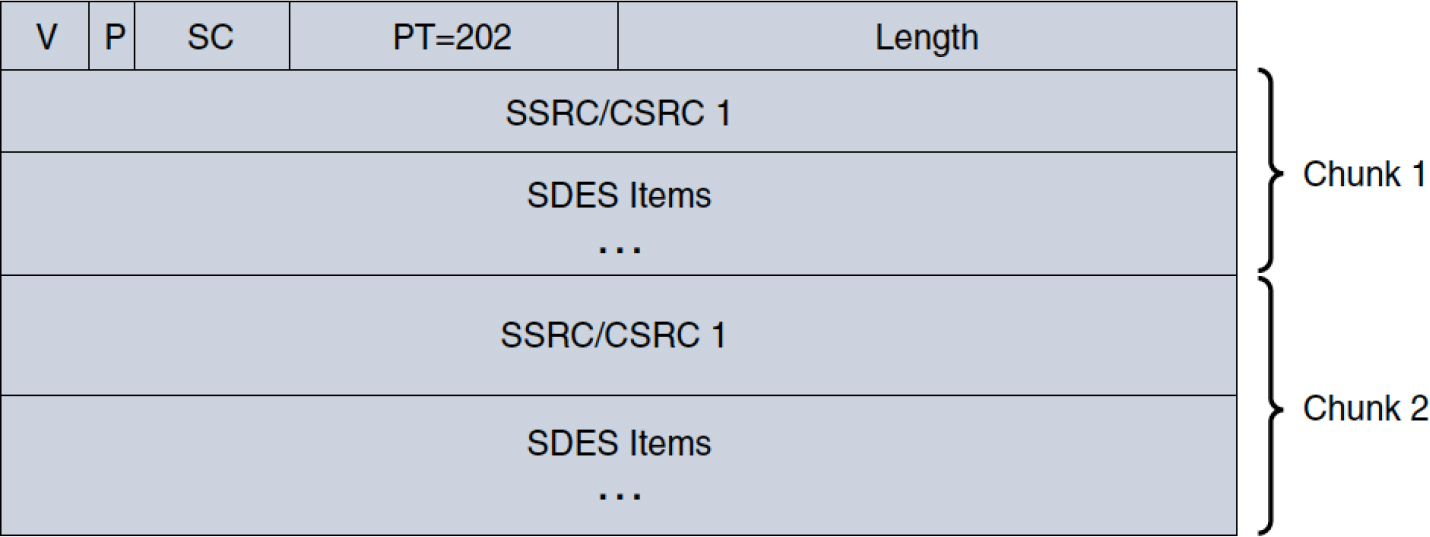
Figure 3-10 SDES Common Packet Format
Each item chunk begins with the SSRC of the sender, followed by a string of entries in the format shown in Figure 3-11. The Type header field conveys the type of the SDES RTCP packet, and the Length header field encodes (as UTF-8) the number of octets of text present.

Figure 3-11 SDES Item Format
The SDES packet format contains the following items:
• The CNAME SDES item carries a Type value of 1 and is the only mandatory SDES packet that must be sent by all implementations. This packet provides a persistent transport-level identifier for the participant, known as the CNAME. The CNAME of a participant is expected to stay the same across SSRC changes and system restarts, and it is expected to be unique in an RTP session or a group of related RTP sessions. The CNAME header field value is derived algorithmically using the format user@host or just host when the username is unavailable. The CNAME is essential for a receiver to identify and synchronize media streams that originate from a given source.
• The NAME SDES item carries a Type value of 2 and is required to provide the name of a participant. This is usually populated by a user and can be in a format chosen by the user (for example, John Doe). Applications can use the NAME SDES item to populate conference rosters as participants join. This SDES item should not be considered unique among all participants in a communication session.
• The EMAIL SDES item carries a Type value of 3 and is used to convey the email of the participant in RFC 2822 format (for example, [email protected]). The email of the participant is expected to remain persistent during the course of an RTP session.
• The PHONE SDES item carries a Type value of 4 and reflects the phone number of the participant in international format.
• The LOC SDES item carries a Type value of 5 and encodes the location of the participants with varying degrees of detail. For example, Building 14, HQ Campus is a valid encoding.
• The TOOL item carries a Type value of 6 and is used to advertise the name of the product or application generating the stream. This is used primarily for marketing purposes and does not have any bearing on the RTP session.
• The NOTE SDES item carries a Type value of 7 and is used to provide a general indication such as a status (for example, on the phone). While this is good for occasional usage, it must not be used for delivery of messages in a communication session, as RTCP is exchanged too infrequently between participants.
• The PRIV SDES item carries a Type value of 8 and is used for experimental purposes.
RTCP Goodbye (BYE) Packet
The RTCP BYE packet is transmitted whenever a participant leaves an RTP session or whenever an SSRC collision is detected. There are certain timing considerations that participants need to take into account while transmitting RTCP BYE messages to prevent congestion. Consider a scenario in which several participants leave an RTP session at around the same time; this could result in a flood of RTCP BYE packets and some RTCP BYE message loss. To prevent this scenario, a back-off algorithm is provided with RTCP BYE transmission.
The format of the RTCP BYE packet is depicted in Figure 3-12; it has the packet type value 203. The SC header field captures the number of SSRC/CSRC identifiers present in this RTCP BYE packet. There is an optional 8-bit field that captures the number of octets present in the following header field, reserved for the purpose of specifying a reason for leaving. The reason for leaving header field provides a textual description of why the source decided to leave the RTP session. An example encoding of this header field could be camera not operational.
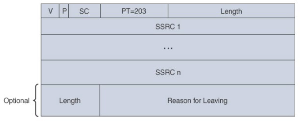
Figure 3-12 RTCP Goodbye Packet Format
RTCP Application-Defined Packet (APP)
The RTCP APP packet allows for application-specific extensions. This packet type is primarily used to exchange proprietary information. As newer application-specific extensions are developed and tested sufficiently, they may evolve to become valid RTCP packet types.
Other RTCP Packet Types
As indicated at the start of this section, there are more RTCP packet formats beyond those defined in RFC 3550, but you might not run into them on many networks. For example, the RTCP Payload Specific Feedback (PSFB) packet type (206) from RFC 4585 may be seen with video endpoints and is signaled in SDP through the SDP attribute a=rtcp-fb. For a complete list of RTCP payload types and references to the specifications where they are defined, visit the following IANA page, which officially registers all the RTCP control packet types: https://www.iana.org/assignments/rtp-parameters/rtp-parameters.xhtml#rtp-parameters-4.
RTCP Transport
As highlighted earlier, for UDP and similar transport layer protocols, applications must use an even port number for RTP and the next higher (odd) port number for RTCP. As detailed in Chapter 2, “VoIP Protocols: SIP and H.323,” applications can utilize the SDP attribute a=rtcp:<udp-port> to define another RTP port rather than the default next highest UDP port number. Furthermore, RFC 5761 introduced the concept of RTP/RTCP multiplexing over a single UDP port. This is conveyed using the SDP attribute a=rtcp-mux.
DTMF Relay
At some point, you have heard a prerecorded prompt requesting some information, perhaps a credit card number, an employee number, or a simple PIN entry. After a couple of presses on the keypad, you magically got the information you were looking for or were connected to a human agent. The underlying framework that enables this seamless transfer of information is known as dual-tone multifrequency (DTMF).
With the advent of voice over IP (VoIP), reliable transmission of keypad button presses end-to-end became somewhat of a problem, as audio codecs were not optimized for carrying DTMF tones without bringing in a degree of distortion. There was a need to engineer a new way of reliably transmitting DTMF, and this solution needed to factor in all the complexities of modern real-time networks. Fortunately, the industry (led by the IETF and ITU-T) came up with several methods of DTMF relay that have worked demonstrably well in real-time networks.
Introduction to DTMF Relay
In the 1960s, Bell Labs introduced DTMF to the public under the trademarked name Touch Tone. It was a means for consumers to utilize tones to convey numeric signaling information. It proved to be a viable alternative to the rotary dial phones that were in use at the time.
DTMF uses a combination of two tones: a high-frequency tone and low-frequency tone interleaved to represent a digit on the keypad (0–9, *, #) or a letter (A–D). A device that supports DTMF has a keypad layout in the form of a 4×4 matrix, such that each row represents the low-frequency tone component and each column represents the high-frequency tone component of the signal. Figure 3-13 illustrates the 4×4 grid used in DTMF signal transmission.
![]()

Figure 3-13 4×4 DTMF Grid
In the illustration in Figure 3-14, a caller at an IP phone dials in to an enterprise network, where the call is routed to an on-premises IVR system. When the call is connected, the IVR system might play a prompt soliciting the caller to enter a digit for the sales department, another digit for the service department, and so on. The caller then enters the desired value through a series of keypad digit presses. Each digit press is a DTMF tone that is conveyed end to end from the caller to the IVR system. Over standard PSTN networks, DTMF information is transmitted as standard signals; over IP networks, DTMF is either transmitted along the signaling (as application protocol messages) or the media stream (within media or RTP packets). The process of transmitting digit information over IP networks—either in-band (within the media), out-of-band (signaling), or a combination of both over different call segments and usually in a mutually exclusive capacity—is called DTMF relay.

Figure 3-14 Sample Ladder Diagram for DTMF
The transmission of signals using DTMF over TDM and analog networks is extremely reliable; however, transmission of DTMF over VoIP networks isn’t so straightforward. Consider the network topology illustrated in Figure 3-15. In this scenario, a remote device is calling in to the enterprise by way of the Internet telephony service provider (ITSP). This call routes through CUBE and Unified CM and ultimately ends up at Cisco Unified Contact Center Express (UCCX). UCCX may play a custom script to the caller, as observed in Figure 3-14, and the user presses 1 on the keypad. The DTMF then needs to be relayed across the different call segments. The process works as follows:
Step 1. The ITSP and CUBE negotiate the in-band RTP-NTE DTMF method, and the DTMF digit is relayed to CUBE from the ITSP.

Figure 3-15 DTMF Relay Along Multiple Call Legs
Step 2. CUBE and Unified CM negotiate the out-of-band (OOB) SIP KPML DTMF method, and the DTMF digit is relayed to Unified CM.
Step 3. Unified CM and UCCX negotiate the default DTMF method of relaying DTMF as JTAPI events, and the DTMF method is relayed to the IVR application to analyze and take action.
This is just a basic example showing how applications can transmit digits over the IP segment(s) of a call. To ensure reliability of DTMF transmission over IP networks, standards bodies such as the IETF and ITU-T have designed several different methods of DTMF relay. These different methods are covered in detail in subsequent sections of this chapter.
Variants of DTMF Relay
Regardless of the scale and complexity of real-time networks, there are only two ways in which DTMF can be relayed over a given call leg:
![]()
• In-band: In-band DTMF relay refers to the transmission of tones within the RTP (media) stream.
• Out-of-band: Out-of-band transmission relies on the signaling channel to transmit DTMF information.
Both methods have merits and issues, and as with many other things in VoIP, the best choice of DTMF relay is implementation dependent and has a scope that spans the entire network end to end, as opposed to being restricted to a few devices or network segments.
In-Band DTMF Relay
Transmission of DTMF tones within the media stream is referred to as in-band DTMF relay. Most of the codecs used in VoIP networks were designed and optimized for human speech, and their encoding and decoding algorithms don’t work well with raw dual-frequency tones. This is especially true with high-compression codecs such as G.729 that sufficiently distort tones so that they cannot be accurately reproduced at the receiving application.
It is precisely for this reason that the IETF took up the task of devising a way to reliably transmit tones within the media stream, which subsequently led to the standardization of named telephony events in RFC 2833 (which has since been superseded by RFC 4733). There are two ways DTMF tones can be transmitted within the media stream:
• Named telephony events (NTEs)
• Raw in-band tones
Named Telephony Events
RFC 2833 defines a specialized payload format and specification for the transmission of DTMF tones within the media stream using named telephony events (NTEs). This specification convincingly overcomes some of the known limitations of transmitting DTMF tones using a standard audio codec. The improvements provided by named telephony events over standard audio codecs for the transmission of DTMF include the following:
• Decoupling of DTMF tones with the audio codec ensures transmission success even when using high-compression codecs such as G.729.
• Defining a separate RTP payload format permits redundancy in DTMF digit transmission while maintaining a low transmission bit rate.
• Certain tones (such as the ANSAM tone for modem calls) have phase reversals. These phase reversals cannot be accurately transported as audio packets over an IP network. Using named telephony events to represent such tones greatly simplifies the process.
• Newer devices can relay DTMF information as named telephony events as opposed to actually generating tone pairs for digits.
The NTE payload is carried in standard RTP packets such that the same sequence number and timestamp space are used for both audio-coded packets and NTE packets.
Note
Further discussion in this chapter uses the term NTE packet to designate an RTP packet that carries an NTE payload.
Three different types of packets are sent per event in the NTE scheme:
![]()
• A packet to designate the start of the DTMF event. The start packet always has the RTP marker (M) bit set to 1. For RFC 2833, there may be three packets with marker bit set to true, and with RFC 4733, only the first packet in the DTMF event needs the marker bit set to true.
• Refresh or update packets that are sent every 50 milliseconds until the end of the event.
• Three redundant packets that designate the end of the event. End packets always have the end (E) bit in the NTE payload set to 1.
The three different types of packets described are for a single event or DTMF digit, and they all have the same RTP timestamp. The sequence number in each successive NTE packet increases by one. Figure 3-16 illustrates the RTP packet format with an NTE payload.

Figure 3-16 RTP Packet Format with an NTE Payload
The payload format for named telephony events is illustrated in Figure 3-17.
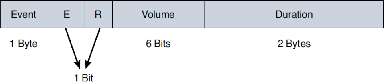
Figure 3-17 Payload Format for Named Telephony Events
The following fields appear within the payload:
• Event: This is a number between 0 and 255 (inclusive), where each number designates a specific event, as outlined in RFC 2833 and RFC 4733. However, for DTMF, the event IDs can take a number between 0 and 15. Table 3-4 lists the digit and alphabetic assignments corresponding to numeric values between 0 and 15.
Table 3-4 DTMF Named Events
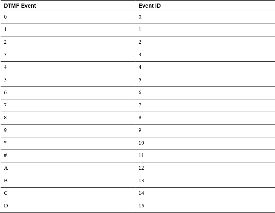
Letters A through D are for military application and are not typically used in commercial applications.
• End (E) bit: When this bit value is set to 1, it designates the end of the DTMF event; it is imperative that this bit not be set to 1 for packets that either designate the start of the event or refresh packets that are sent every 50 milliseconds.
• Volume: For DTMF digits and other events that can be represented as tones, this field describes the power level of the tone, expressed in dBm0 after dropping the sign. Power levels range from 0 to −63 dBm0. The range of valid DTMF is from 0 to −36 dBm0.
• Duration: This field designates, in timestamp units, the duration of the DTMF event. The timestamp field in any RTP packet for a given event indicates the instant when the event started, while the Duration field in any NTE packet for a given event indicates how long the event has lasted.
• R bit: This a reserve bit and currently does not have any defined function.
Note
There are scenarios in which the timestamp can change within the span of a single event; this occurs when the event lasts longer than 8 seconds.
Given that named telephony events are carried within the media stream along with audio-encoded packets, the receiving application distinguishes these packets from standard audio packets by using the payload type and payload format. For NTE packets, the payload types chosen are dynamic and can vary between 96 and 127. For communication sessions set up using SIP in concert with SDP, the payload type for named telephony events is advertised by each user agent within the corresponding SDP body. Example 3-3 provides an SDP snippet that advertises a dynamic payload of 101 for NTE DTMF.
![]()
Example 3-3 SDP Advertisement of Named Telephony Events
// SIP message omitted for brevity//
v=0
o=CiscoSystemsSIP-GW-UserAgent 1597 5834 IN IP4 10.94.64.12
s=SIP Call
c=IN IP4 10.1.1.1
t=0 0
a=recvonly
m=audio 17389 RTP/AVP 8 101
a=rtpmap:8 PCMA/8000
a=rtpmap:101 telephone-event/8000
a=fmtp:101 0-15
a=ptime:20
Although the payload type 101 is most commonly used for NTE, it is perfectly valid to make use of any payload type between 96 and 127. It is worth noting that dynamic payload types can be negotiated asymmetrically. This simply means that when negotiating NTE on a call leg, the two user agents may advertise different payload types for NTE. Consider the scenario in Figure 3-18, where User Agent A advertises payload type 96 for NTE, and User Agent B advertises payload type 101. Recall from Chapter 2 that SDP describes what a user agent is prepared to receive. Therefore, when User Agent A offers payload type 96 for DTMF, User Agent B must send DTMF using payload type 96. Likewise, when User Agent B answers with payload type 101 for DTMF, User Agent A must send DTMF using payload type 101. While rare, this scenario is certainly permitted by SDP, so the user agents need to be configured properly to allow for such asymmetric negotiation.

Figure 3-18 Asymmetric Payload Type Negotiation for NTE
Raw In-Band Tones
Raw in-band DTMF refers to the transmission of raw tones within the media stream. Unlike named telephony events, for which there is a specialized RTP payload format for DTMF, raw in-band DTMF encodes tone frequencies within the standard RTP payload. As mentioned earlier, audio codecs have their algorithms optimized for speech and don’t work optimally to transmit DTMF tones. Using high-compression codecs for transmission of DTMF, tones are almost certain to impede DTMF transmission due to significant tone distortion.
Some of the inherent disadvantages of using raw in-band DTMF are as follows:
• Lack of codec optimization for transmission of DTMF.
• No native support for redundancy while transmitting DTMF tones (unlike NTE, which has built-in redundancy). If redundancy has to be achieved, it occurs through a redundant RTP stream using the constructs of RFC 2198. This leads to increased complexity and bandwidth utilization.
• Lack of diagnostics for troubleshooting. Because these tones are carried as raw tones within the audio codec, the only way to troubleshoot DTMF transmission is by decoding the audio stream using specialized software.
• Non-ubiquitous adoption across devices and vendors.
There are still some service providers that use this method of DTMF transmission, despite the obvious perils and limitations. Figure 3-19 diagrammatically depicts a sample transmission of RTP-NTE and raw in-band DTMF. The top half of the diagram shows a call that is connected to an on-premises enterprise IVR. The PSTN phone presses 4 and ultimately sends an RTP-NTE packet with event ID 4 conveying the digit press to the local enterprise SBC. The local SBC then sends the RTP-NTE packet with the event ID to the remote IVR, which processes the digit press and takes action.
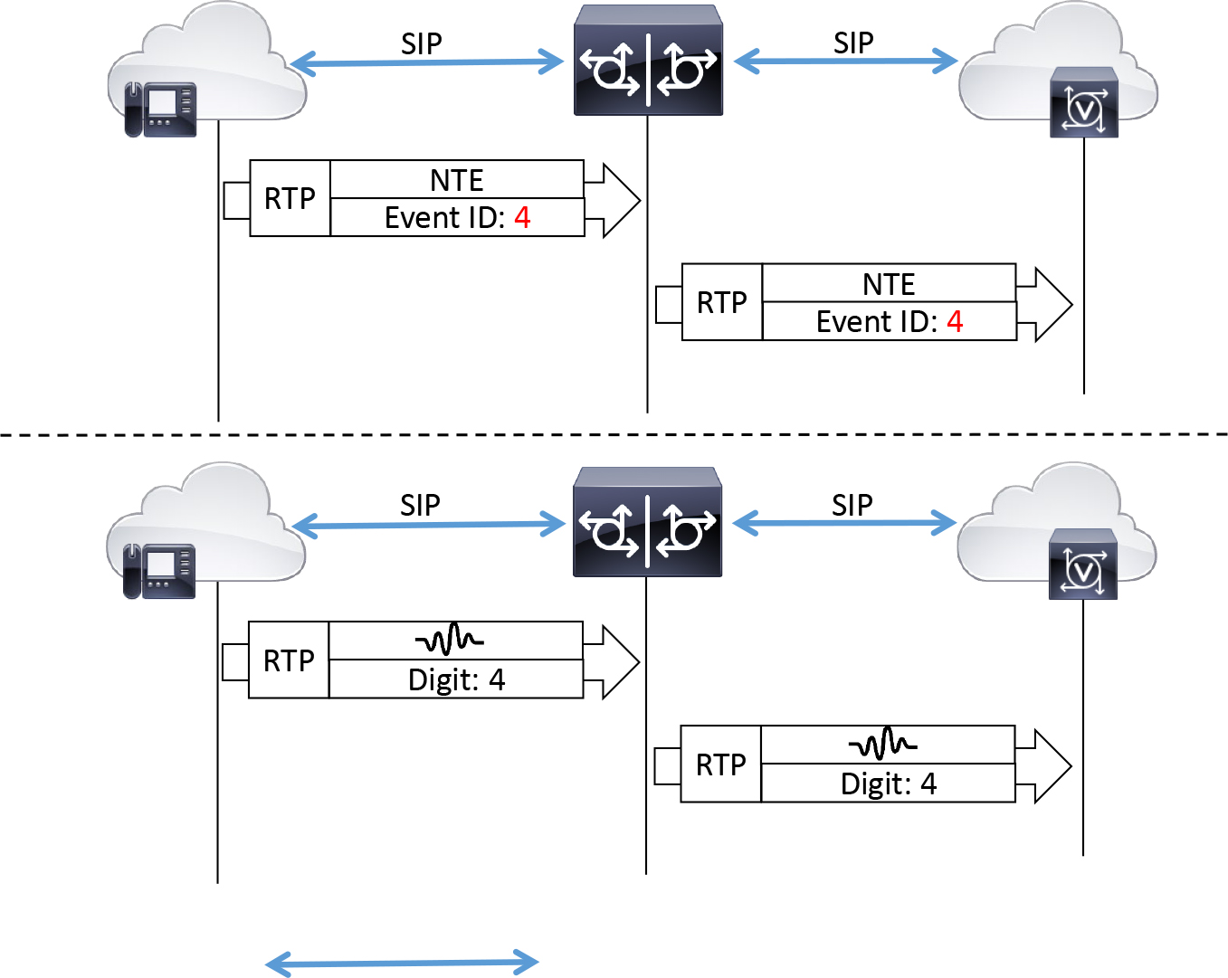
Figure 3-19 End-to-End Transmission of NTE and Raw In-Band DTMF
The bottom half of Figure 3-19 shows the same sample call, which is connected to an enterprise IVR by a remote PSTN participant through an on-premises SBC, such as CUBE. However, when the PSTN phone presses the digit 4, a raw in-band RTP packet is sent. The payload of the RTP packet contains the encoded audio, which comprises the two frequencies interleaved to produce the tone for the DTMF digit 4. The SBC passes the RTP packet to the on-premises IVR, which needs to be equipped with a mechanism for detecting these in-band dual tones. If this IVR is capable of detecting the 770 Hz × 1209 Hz tones within the audio stream, it may take action based on the reception of digit 4. If the remote IVR is not equipped with a mechanism to detect raw in-band DTMF, the IVR may wait for user input or repeat the same prompts continuously until the call disconnects.
Out-of-Band DTMF Relay
Out-of-band DTMF relay relies on the signaling channel to communicate digit presses. Call control protocols such as SIP and H.323 have specialized mechanisms and extensions for communicating DTMF information. These mechanisms and extensions are discussed in detail in the sections that follow. With this method of DTMF relay, notifications for digit presses traverse the signaling path, which could include call agents and stateful proxies, among other devices. On the other hand, in-band DTMF relay uses the media path and is relayed directly between the participants of an RTP session. Figure 3-20 depicts the difference in path characteristics of in-band and out-of-band DTMF.
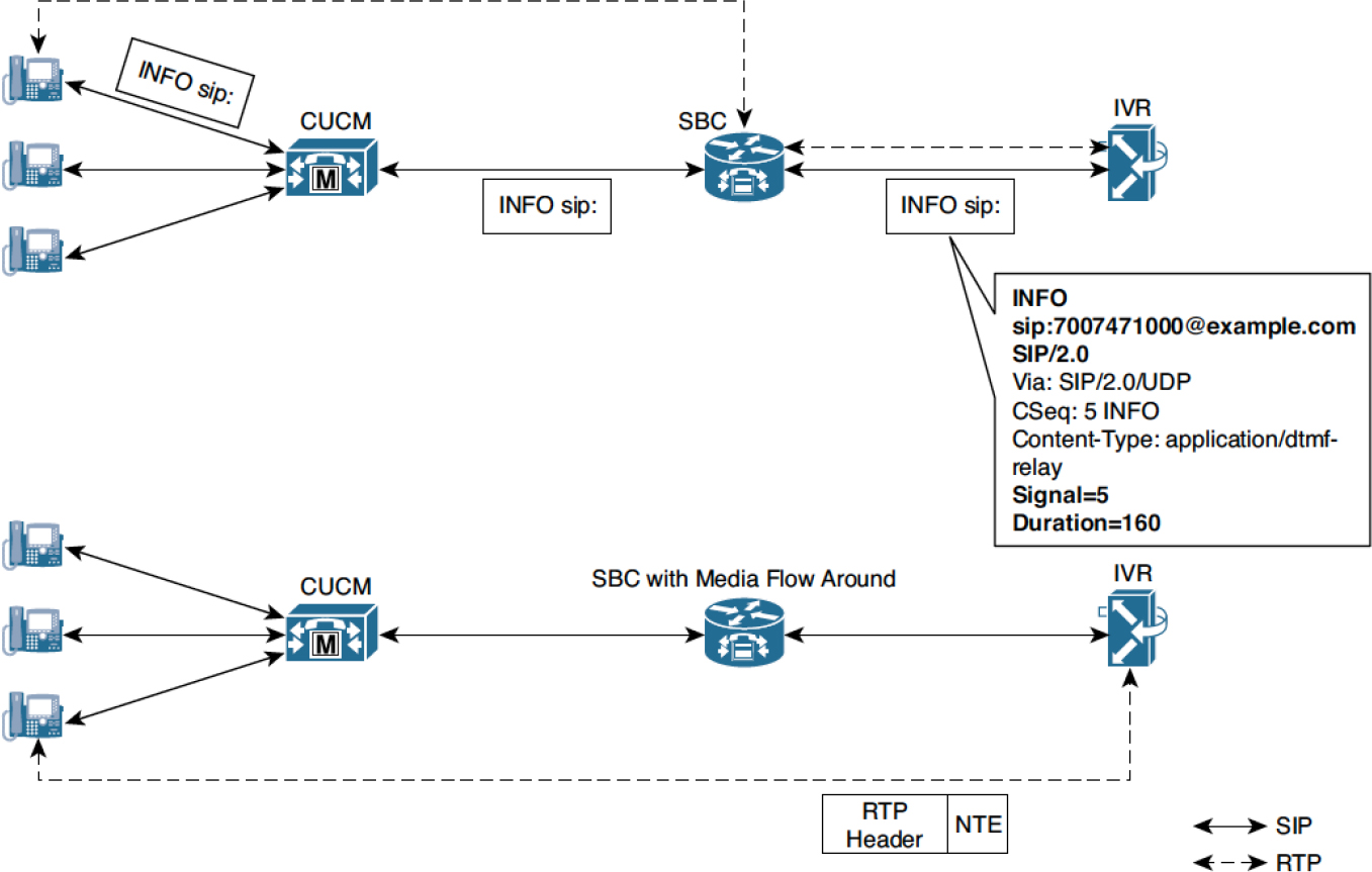
Figure 3-20 Difference in Path Traversed by In-Band and Out-of-Band DTMF
The following subsections discuss different methods of out-of-band DTMF relay in SIP and H.323 networks.
SIP INFO
The procedures laid out in RFC 3261 and several accompanying RFCs define the operating principles, methods, and extensions that make SIP a robust multipurpose communication protocol. Defined originally in RFC 2976, the SIP INFO method is one such extension to SIP, designed to allow exchange of application-level information along the signaling path.
The information that could be transmitted using SIP INFO was varied and, in a way, limitless, as it could be tailor made for any application usage. For example, a vendor could leverage SIP INFO to transmit resource availability information or billing information or even proprietary information. Over the years, SIP INFO has evolved into a convenient way to communicate application information spanning a broad spectrum of use cases, including the following:
• DTMF transmission
• QSIG encapsulation
• Fast video update requests
• Billing
Originally, application information could be carried in INFO message bodies or in specific SIP headers; the drawback of this approach was the lack of semantics on how specific application-level information is transmitted. For example, with DTMF, without a clear set of rules indicating how DTMF digits are transmitted from one node to another, does the application indicate digit presses in the INFO message headers or the body? If included in the body, what parameters should be used?
RFC 6086 was developed in an effort to standardize what information could be transmitted using INFO messages and the semantics of how that application-level information is delivered. RFC 6086 allows for the creation of “info packages” that dictate the content and semantics of the information transmitted between applications; that is, different info packages can be designed to transmit different application-level information such as DTMF, billing, or resource availability information.
At the time of this writing, there is no standardized method for transmitting DTMF information using the guidelines of RFC 6086. All implementations that choose to transmit DTMF using SIP INFO do so using the guidelines of RFC 2976.
Support for the SIP INFO method is advertised in the SIP Allow header field of SIP requests and responses. The INFO method is a request and has to be answered by a 200 OK response. The streaming of a SIP INFO message does not create a new SIP dialog between user agents. Rather, it is sent on the existing dialog created by a SIP INVITE message.
Example 3-4 shows a sample SIP INFO message for DTMF digit 1, with a duration of 160 milliseconds.
Example 3-4 SIP Message Output for a SIP INFO Message
INFO sip:[email protected] SIP/2.0
Via: SIP/2.0/UDP 10.1.1.2:5060
From: <sip:[email protected]>;tag=43
To: <sip:[email protected]>;tag=9753.0207
Call-ID: [email protected]
CSeq: 25634 INFO
Supported: 100rel
Supported: timer
Content-Length: 26
Content-Type: application/dtmf-relay
Signal= 1
Duration= 160
Notice in Example 3-4 that the content type is specified as application/dtmf-relay. In some implementations, it can also be encoded as application/dtmf, although the former variant is more popular.
Note
SIP INFO is covered here for completeness, but most Cisco products either don’t support it at all or have very limited support (for example, they are unable to send SIP INFO but are able to receive it and immediately convert it to RTP-NTE).
SIP KPML
SIP Key Press Markup Language (KPML), defined in RFC 4730, is used to monitor key presses. Before describing the working of SIP KPML in the transmission of DTMF, it is important to understand the underlying framework governing its operation. SIP KPML works on the subscribe/notify framework, which involves a subscriber and a notifier. The subscriber is a user agent that initiates a subscription for event updates or state information to the notifier, and the notifier is a user agent that notifies the subscriber of any state change or observed events.
To receive event notifications from another user agent, the subscriber sends a SIP SUBSCRIBE message with an Event header; the contents of this header indicate the set of events for which for notifications are solicited. The Event header includes at most a single value, which corresponds to the name of the event package for which notifications are requested. Event packages are SIP extensions that build on the subscribe/notify framework of RFC 6665 to fit a specific usage paradigm. Several event packages are standardized as RFCs, and KPML is the one for DTMF.
Once a SUBSCRIPTION request has been accepted, the notifier sends a SIP NOTIFY message to communicate observed events or changes in state information, such that it includes the same event package specified in the SUBSCRIBE request. Figure 3-21 describes the exchange between user agents that support the subscribe/notify framework.
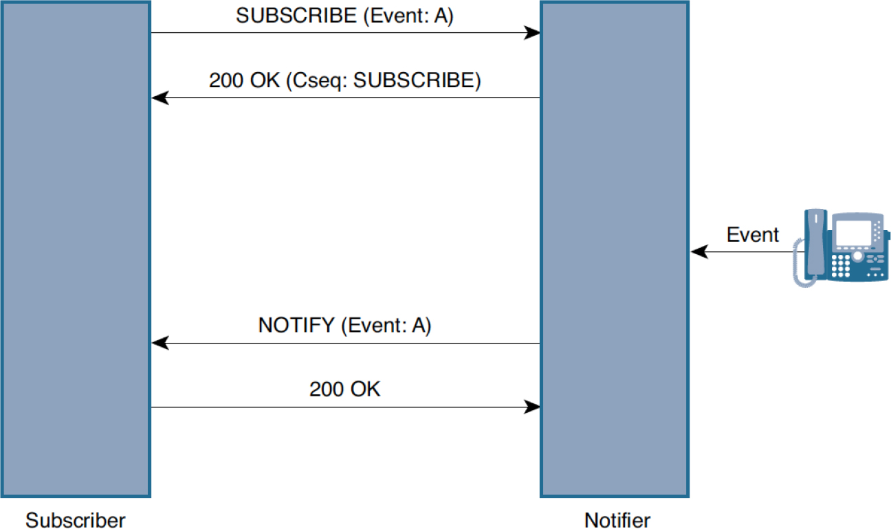
Figure 3-21 SIP Subscribe/Notify Framework
Each event package that is used in the subscribe/notify framework specifies a set of rules that operationally and syntactically define headers, message bodies, and information exchanged in a SUBSCRIBE or NOTIFY transaction. Support for this framework can be indicated in any of the following ways:
• With the SUBSCRIBE method in the Allow header field of SIP requests and responses
• In the Allow-Events header field
• Using the methods parameter of the Contact header
Each accepted subscription is active for a specific duration and has to be refreshed by the subscriber. The duration for which the subscription remains active is defined by the Expires header field value. The subscriber must refresh a subscription before it expires by sending a new SUBSCRIBE message. Figure 3-22 depicts the subscription refresh process.
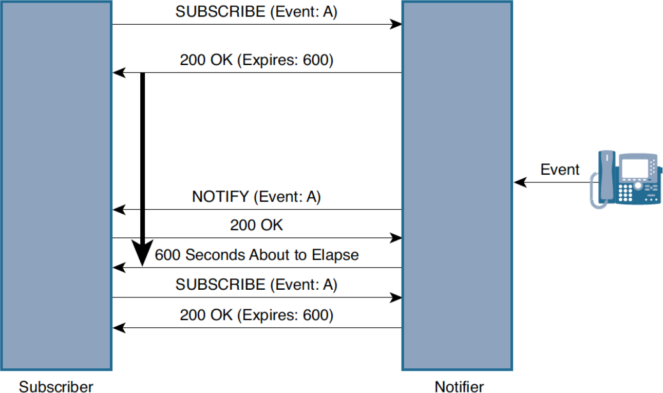
Figure 3-22 Refreshing Subscriptions
A user agent can unsubscribe from state or event notifications by sending a SUBSCRIBE message with the Expires header field value set to 0. Once the subscriber terminates a subscription, the notifier must not send further NOTIFY requests carrying event or state information.
While sending a SIP NOTIFY to the subscriber, the notifier must include the same event package as specified in the SUBSCRIBE request, along with the current state of the subscription, which can take one of three values:
• Active: Indicates that the SUBSCRIBE request has been accepted
• Pending: Indicates that there is insufficient policy or administrative information to accept or deny the subscription
• Terminated: Indicates that the subscription has terminated, and no new notifications will be sent
Drawing from the concepts discussed, the operation of the subscribe/notify framework can be summarized as follows:
Step 1. A user agent that requires event or state information updates from another entity (the notifier) and sends a SIP SUBSCRIBE request, referencing a specific event package in the Event header field.
Step 2. On receiving the SIP SUBSCRIBE request, assuming that the notifier understands the event package specified in the Event header field, a 200 OK is sent in response to the SUBSCRIBE request. A SIP SUBSCRIBE is a dialog-creating request and need not always exist within a dialog established by an INVITE/200 OK exchange.
Step 3. The duration for which the subscription is valid is specified in the Expires header of the 200 OK sent in response to the SUBSCRIBE request.
Step 4. As soon as the subscription has been accepted, the notifier must send a SIP NOTIFY message, regardless of whether it has any event or state information to communicate at the instant the subscription was accepted. If it does not have any event or state information to communicate at the instant the subscription was accepted, it sends a SIP NOTIFY message with an empty message body.
Step 5. The notifier triggers a SIP NOTIFY request every time there is a change in state information or an observed event. The NOTIFY message must contain the same Event header field value as the SUBSCRIBE request and must include the Subscription-State header field value.
Step 6. The subscriber must ensure that subscriptions are refreshed in a timely manner. If the subscriber does not wish to receive any further event notifications, it can explicitly terminate the subscription at any time.
As mentioned earlier in this chapter, SIP KPML, defined in RFC 4730, uses the subscribe/notify framework to report digit presses by using Extensible Markup Language (XML) documents known as KPML. XML documents are exchanged in the bodies of the SUBSCRIBE and NOTIFY messages. In a SUBSCRIBE message, the XML document serves to specify the digits or pattern(s) of interest, whereas in the NOTIFY message, it specifies the actual patterns or digits collected.
The operational principles of SIP KPML are governed by the kpml event package, which has to be included as an event package in every SUBSCRIBE and NOTIFY message used in the KPML framework.
There are two categories of KPML subscriptions, and they differ in the duration for which subscriptions are kept alive:
• One-shot subscriptions
• Persistent subscriptions
A one-shot subscription terminates as soon as a pattern match occurs and a NOTIFY message is sent (that is, the Subscription-State header value is set to terminated). For further pattern match notifications, a new SUBSCRIBE dialog has to be initiated. Figure 3-23 illustrates a one-shot subscription.
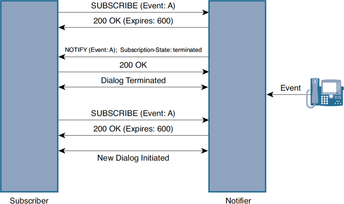
Figure 3-23 One-Shot Subscription
Persistent subscriptions remain active until explicitly terminated, regardless of whether a pattern match is indicated with a SIP NOTIFY message. Persistent subscriptions have two further variants: single-notify and continuous-notify subscriptions. A single-notify subscription sends a NOTIFY message on a pattern match but buffers or withholds further notifications until a new subscription is received (on the same dialog). Figure 3-24 illustrates a persistent single-notify subscription.
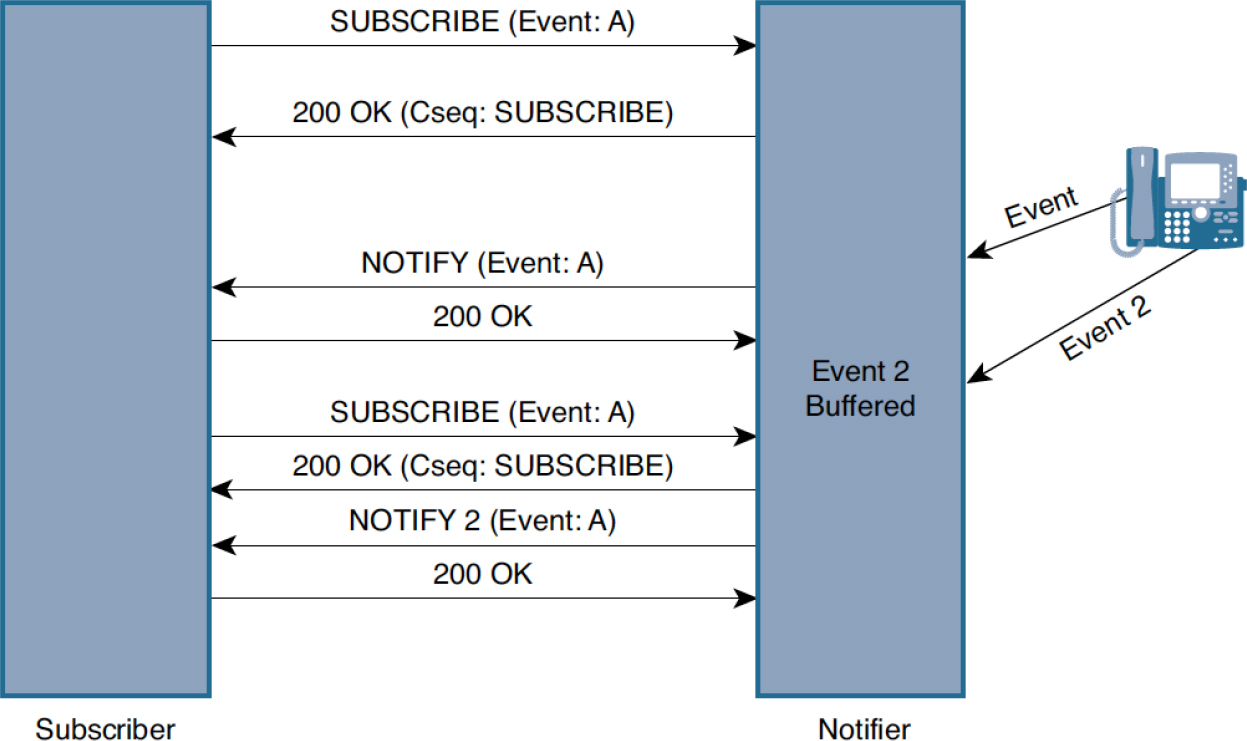
Figure 3-24 Single-Notify Subscription
A continuous-notify subscription sends notifications every time there is a pattern match. Figure 3-25 demonstrates the exchange and subscription state of a persistent continuous subscription.

Figure 3-25 Continuous Subscription
KPML documents sent in SIP SUBSCRIBE messages indicate patterns of interest for an application. Each KPML document contains a <pattern> element; embedded within this element are a series of <regex> elements that indicate individual digit maps. The use of multiple <regex> elements within a KPML document is required when user input can match a plurality of potential patterns, such as user input dialing while dialing numbers within the scope of the North American Numbering Plan (NANP).
Note
KPML is extensively used to indicate digits pressed while dialing a phone number and is not restricted to reporting only DTMF information. Many of Cisco’s IP phones use KPML to indicate the dial string while initiating a call with Unified CM.
However, from the perspective of DTMF, a single <regex> element suffices, as the events to be reported are restricted to the ones indicated in Table 3-4.
Example 3-5 provides a snippet of a sample KPML document that solicits DTMF event notification.
Example 3-5 KPML Document Snippet
<?xml version="1.0” encoding="UTF-8” ?>

<kpml-request xmlns="urn:ietf:params:xml:ns:kpml-request” xmlns:xsi="http://
www.w3.org/2001/XMLSchema-instance” xsi:schemaLocation="urn:ietf:params:xml:ns:
kpml-request kpml-request.xsd” version="1.0">


<pattern interdigittimer="7260000” persist="persist">

<regex tag="dtmf">[x*#ABCD]</regex>

</pattern>


</kpml-request>
In Example 3-5, the <pattern> element encloses the digit map against which DTMF event notifications are sent. The actual digit map string is included in the <regex> element. For the notifier to distinguish between persistent and one-time subscriptions (described previously), the persist attribute of the <pattern> element is used. The persist attribute can take one of the following values:
• one-shot: Indicates one-shot subscriptions
• single-notify: Indicates single-notify subscriptions
• persist: Indicates continuous-notify subscriptions
In the case of DTMF, subscriptions are always persistent, as it does not make sense to send a new SIP SUBSCRIBE message for each DTMF digit in a call.
The interdigittimer attribute is used when the notifier transmits dial-string information. However, in the case of DTMF notification, this timer isn’t of consequence and is set to a sufficiently high value.
When a multitude of patterns are specified in a subscription and the subscriber wants to know which particular digit map was matched, it can include the tag attribute in each <regex> element. When there is a match at the notifier for a specific digit map, the notifier includes the appropriate tag in the NOTIFY message that has the KPML report. Example 3-5 uses the dtmf tag in the <regex> element and is operationally redundant as there is only a single digit map specified for DTMF patterns.
Example 3-6 provides a snippet of a SIP NOTIFY message that is sent in response to a DTMF event.
Example 3-6 SIP NOTIFY Message Sent in Response to a DTMF Event
NOTIFY sip:10.1.1.1:5060;transport=tcp SIP/2.0
Via: SIP/2.0/TCP 10.1.1.1:5060;branch=z9hG4bK624B9
Call-ID: [email protected]
!! Message truncated for brevity!!
Event: kpml
Subscription-State: active
Content-Type: application/kpml-response+xml
Content-Length: 113
Message Body
<?xml version="1.0” encoding="UTF-8"?><kpml-response version="1.0” code="200” text="OK” digits="1” tag="dtmf"/>
In Example 3-6, a notification is received for a DTMF event. Within the body of the SIP NOTIFY message is embedded a KPML document that is also known as a KPML report. A KPML report for DTMF includes the following mandatory and optional attributes:
• code (mandatory)
• text (mandatory)
• digit (optional)
• tag (optional)
The code and text attributes are mandatory and must be part of every KPML report, regardless of whether digits are reported. For example, when the KPML subscription terminates, the KPML report contains the body specified in Example 3-7. The digit attribute is used to specify the specific digit matched against the digit map included in the KPML body of the SUBSCRIBE request. As mentioned earlier, the tag attribute is used to distinguish between multiple potential patterns.
Example 3-7 is a snippet of the SIP NOTIFY message sent in response to a subscription termination.
Example 3-7 SIP NOTIFY Message Sent in Response to a Subscription Termination
NOTIFY sip:[email protected]:5060 SIP/2.0
Via: SIP/2.0/UDP 10.10.1.1.1:5060;branch=z9hG4bK6BE90
Call-ID: [email protected]
Event: kpml
Subscription-State: terminated
Content-Type: application/kpml-response+xml
Content-Length: 109
Message Body
<?xml version="1.0” encoding="UTF-8"?><kpml-response version="1.0"
code="487” text="Subscription Expired"/>
As demonstrated in Example 3-7, the code and text attributes are different from what is reported in Example 3-6.
As mentioned earlier in this section, Cisco IP phones use SIP KPML to convey digits pressed on the keypad when a user is initializing a call. At a high level, the sequence of events for SIP KPML with IP phones and Unified CM is as follow:
![]()
Step 1. The IP phone starts the conversation by sending a SIP INVITE containing the first digit dialed by the IP phone user and includes the SIP Header field value Allow-Events: kpml.
Step 2. Unified CM answers the INVITE with a 100 Trying and then sends a SIP SUBSCRIBE to initiate the KPML persist subscription. The IP phone sends a 200 OK response acknowledging the SUBSCRIBE.
Step 3. Shortly after the 200 OK, the IP phone sends a SIP NOTIFY for KPML with the SIP Header field set to Subscription-State: active; expires=7200. Upon receipt of the NOTIFY message, Unified CM sends a 200 OK response to acknowledge that the subscription is now active.
Step 4. From this point forward, any digit pressed by the user is sent as a SIP NOTIFY with a KPML-XML message body indicating the digit pressed by the user. Unified CM acknowledges these incoming digits with a 200 OK and attempts to route the call. The process of Unified CM call routing and digit analysis is detailed in Chapter 4, “Unified CM Call Routing and Digit Manipulation.”
Step 5. These two messages, NOTIFY and 200 OK, continue until an applicable device is found, at which point Unified CM tears down the KPML subscription with a SIP SUBSCRIBE and Expires: 0 in the SIP Header field.
Example 3-8 details snippets of these SIP messages highlighted with comments tying the snippets to the previous steps.
Example 3-8 SIP KPML Digits from IP Phone to Unified CM
### Step 1, INVITE first digit
INVITE sip:1@172.18.110.48;user=phone SIP/2.0
Via: SIP/2.0/TCP 14.50.214.122:51851;branch=z9hG4bK237b00c1
From: “1008” <sip:[email protected]>;tag=2c31246a214b001e70267f66-4e773ec7
To: sip:[email protected]
Call-ID: [email protected]
[..truncated..]
Allow-Events: kpml,dialog

### Step 2, KPML SUBSCRIBE
SUBSCRIBE sip:[email protected]:51851;transport=tcp SIP/2.0
Via: SIP/2.0/TCP 172.18.110.48:5060;branch=z9hG4bK39f3915f65e35
From: <sip:[email protected]>;tag=512298967
To: sip:[email protected]
Call-ID: [email protected]
CSeq: 101 SUBSCRIBE
Event: kpml; [email protected]; from-tag=2c31246a214b001e70267f66-4e773ec7
Expires: 7200
Contact: sip:[email protected]:5060;transport=tcp
Accept: application/kpml-response+xml
Max-Forwards: 70
Content-Type: application/kpml-request+xml
Content-Length: 424

<?xml version="1.0” encoding="UTF-8” ?>
<kpml-request xmlns="urn:ietf:params:xml:ns:kpml-request” xmlns:xsi="http://www.w3.org/2001/XMLSchema-instance” xsi:schemaLocation="urn:ietf:params:xml:ns:kpml-request kpml-request.xsd” version="1.0">

<pattern criticaldigittimer="1000” extradigittimer="500” interdigittimer="15000” persist="persist">
<regex tag="Backspace OK">[x#*+]|bs</regex>
</pattern>

</kpml-request>

### Step 3, KPML Subscription Active
NOTIFY sip:[email protected]:5060;transport=tcp SIP/2.0
Via: SIP/2.0/TCP 14.50.214.122:51851;branch=z9hG4bK3cdda3dd
To: <sip:[email protected]>;tag=512298967
From: <sip:[email protected]>;tag=2c31246a214b0020180d09b3-1a336107
Call-ID: [email protected]
CSeq: 1000 NOTIFY
Event: kpml
Subscription-State: active; expires=7200
Max-Forwards: 70
Contact: <sip:[email protected]:51851;transport=tcp>;+u.sip!devicename.ccm.cisco.com="SEP2C31246A214B"
Allow: ACK,BYE,CANCEL,INVITE,NOTIFY,OPTIONS,REFER,REGISTER,UPDATE,SUBSCRIBE
Content-Length: 0

### Step 4, NOTIFY DIGIT and 200 OK
NOTIFY sip:[email protected]:5060;transport=tcp SIP/2.0
Via: SIP/2.0/TCP 14.50.214.122:51851;branch=z9hG4bK3fb50fc1
To: <sip:[email protected]>;tag=512298967
From: <sip:[email protected]>;tag=2c31246a214b0020180d09b3-1a336107
Call-ID: [email protected]
CSeq: 1001 NOTIFY
Event: kpml
Subscription-State: active; expires=7200
Max-Forwards: 70
Contact: <sip:[email protected]:51851;transport=tcp>;+u.sip!devicename.ccm.cisco.com="SEP2C31246A214B"
Allow: ACK,BYE,CANCEL,INVITE,NOTIFY,OPTIONS,REFER,REGISTER,UPDATE,SUBSCRIBE
Content-Length: 205
Content-Type: application/kpml-response+xml
Content-Disposition: session;handling=required

<?xml version="1.0” encoding="UTF-8"?>
<kpml-response xmlns="urn:ietf:params:xml:ns:kpml-response” version="1.0” code="200” text="OK” suppressed="false” forced_flush="false” digits="0" tag="Backspace OK"/>

SIP/2.0 200 OK
Via: SIP/2.0/TCP 14.50.214.122:51851;branch=z9hG4bK3fb50fc1
From: <sip:[email protected]>;tag=2c31246a214b0020180d09b3-1a336107
To: <sip:[email protected]>;tag=512298967
Call-ID: [email protected]
CSeq: 1001 NOTIFY
Server: Cisco-CUCM12.5
Content-Length: 0

NOTIFY sip:[email protected]:5060;transport=tcp SIP/2.0
CSeq: 1002 NOTIFY
<kpml-response xmlns="urn:ietf:params:xml:ns:kpml-response” version="1.0” code="200” text="OK” suppressed="false” forced_flush="false” digits="1" tag="Backspace OK"/>

NOTIFY sip:[email protected]:5060;transport=tcp SIP/2.0
CSeq: 1003 NOTIFY
<kpml-response xmlns="urn:ietf:params:xml:ns:kpml-response” version="1.0” code="200” text="OK” suppressed="false” forced_flush="false” digits="0" tag="Backspace OK"/>

### Step 5, KPML teardown
SUBSCRIBE sip:[email protected]:51851;transport=tcp SIP/2.0
Via: SIP/2.0/TCP 172.18.110.48:5060;branch=z9hG4bK39f3a438a29b4
From: <sip:[email protected]>;tag=512298967
To: <sip:[email protected]>;tag=2c31246a214b0020180d09b3-1a336107
Call-ID: [email protected]
CSeq: 102 SUBSCRIBE
Event: kpml; [email protected]; from-tag=2c31246a214b001e70267f66-4e773ec7
Expires: 0
Contact: sip:[email protected]:5060;transport=tcp
Max-Forwards: 70
Content-Length: 0
Figure 3-26 shows a SIP ladder diagram with the events discussed in the previous steps and shown in Example 3-8.

Figure 3-26 SIP Ladder Diagram of SIP KPML with IP Phone and Unified CM
SIP Notify
The out-of-band methods of DTMF relay discussed so far are widely adopted in SIP-based networks; however, in terms of the amount of information disseminated, there are a few shortcomings. For example, in the case of SIP INFO, it is impossible to determine when the DTMF event actually began. In addition, many vendors use default event duration values for DTMF that fail to accurately capture the actual event duration. In the case of SIP KPML, digit notifications sent in the KPML report capture only the actual digit event, without providing much detail around how long the digit press event lasted, which could lead to issues when these tones have to be reproduced on a POTS interface (such as an ISDN circuit) or converted to another DTMF encoding scheme.
The section “SIP KPML,” earlier in this chapter, provides an introduction to the SIP subscribe/notify framework, in which SIP NOTIFY messages are used to transmit specific event notifications or changes in state information. However, for notifications to be sent from one user agent to another, there always has to be an explicit, approved subscription in place (set up by the SIP SUBSCRIBE method). SIP NOTIFY, sometimes called “unsolicited NOTIFY,” tweaks this framework by sending notifications for events such as DTMF and message-waiting indicators (MWIs) without an explicit subscription in place. This is a Cisco-proprietary implementation and is not standardized in any IETF RFC.
The unsolicited NOTIFY framework borrows heavily from the framework standardized in RFC 2833/4733 by reusing and slightly tweaking the payload format highlighted earlier, in Figure 3-17. The use of this payload format provides the following benefits:
• It provides an explicit means of indicating when the DTMF event begins (by not setting the E bit).
• It allows for sending incremental updates that accurately capture the event duration.
• It can explicitly signal the end of the event if the E bit is set.
Unsolicited NOTIFY cannot be negotiated with SDP or by using custom event packages such as KPML. Support for unsolicited NOTIFY is indicated with the Call-Info header field value; it is advertised in the SIP INVITE message and reciprocated by the answering side in a 18X/200 response. Example 3-9 provides a sample snippet of unsolicited NOTIFY negotiation between a UAS and a UAC.
Example 3-9 SIP Message Snippet for Unsolicited NOTIFY Negotiation
INVITE sip:[email protected]:5060 SIP/2.0
Via: SIP/2.0/UDP 10.1.1.2:5060;branch=z9hG4bKBC3516C
!!! Message truncated for brevity!!!
CSeq: 101 INVITE
Contact: <sip:[email protected]:5060>
Call-Info: <sip:10.1.1.2:5060>;method="NOTIFY;Event=telephoneevent;Duration=2000"
Expires: 180
Allow-Events: telephone-event

SIP/2.0 180 Ringing
Via: SIP/2.0/UDP 10.1.1.2:5060;branch=z9hG4bKBC3516C7
CSeq: 101 INVITE
!!! Message truncated for brevity!!!
Contact: <sip:[email protected]:5060>
Call-Info: <sip:10.1.1.1:5060>;method="NOTIFY;Event=telephoneevent;Duration=2000"
Content-Length: 0
Note
The UAS can indicate support for unsolicited NOTIFY in the 200 OK message as well.
While negotiating bidirectional support for unsolicited NOTIFY through the exchange of the Call-Info header, the Duration header field value is of significant interest as it does not indicate the default value for all DTMF events in the dialog. Rather, it indicates the amount of time between successive NOTIFY messages sent for a single DTMF event.
It has already been established that unsolicited NOTIFY borrows heavily from the framework of RFC 2833/4733, using a similar payload structure and operating principle for DTMF event indication. The major difference between the two is that RFC 2833/4733 sends the payload within RTP packets, while unsolicited NOTIFY uses the SIP NOTIFY method body to encode the payload in binary.
An actual Unsolicited SIP NOTIFY message with a sample digit in the message body has not been shown in this text because the binary payload type does not translate well to text. The payload format for SIP NOTIFY/unsolicited NOTIFY is diagrammed in Figure 3-27.
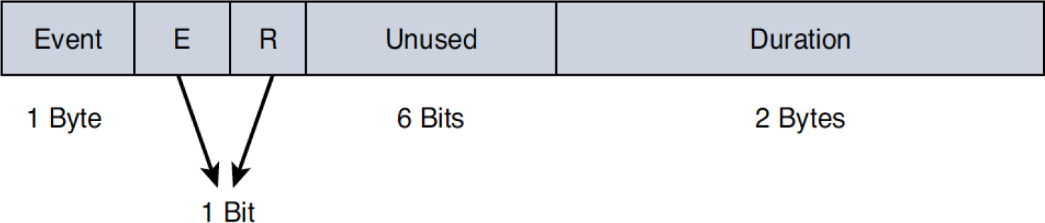
Figure 3-27 Payload Format of an Unsolicited SIP NOTIFY
The payload format for SIP NOTIFY is strikingly similar to that of named telephony events, with the exception of the Volume field and the way the Duration field is expressed. The Volume field is left undefined in the case of SIP NOTIFY, primarily because it is an out-of-band method of DTMF relay. The Duration field is measured in milliseconds in the case of SIP NOTIFY instead of in timestamp units.
In addition to using a similar payload format for the transmission of DTMF events, unsolicited NOTIFY also uses three packet types per DTMF event:
• Start packet
• Refresh packet(s)
• End packet
Unsolicited NOTIFY for DTMF works as follows:
Step 1. As soon as DTMF stimulus is detected, a start SIP NOTIFY message is sent, such that the payload Duration field value mirrors the duration negotiated in the Call-Info header of the INVITE–18X/200 exchange. Because this is an out-of-band method of DTMF transmission, the M bit (found only in the RTP packet headers) cannot be set to 1. Instead, the E bit is set to 0, indicating that the event is in progress.
Step 2. If the actual DTMF event is of shorter duration than what was specified in the Duration field value of the start NOTIFY message, another NOTIFY is sent, with the E bit set to 1, indicating the end of the DTMF event. In addition, the Duration field value is updated to indicate the actual event duration. For example, if the start NOTIFY message was sent with a duration of 2000 milliseconds and the actual DTMF event lasted 800 milliseconds, then an end NOTIFY message (with the E bit set) is sent with an updated Duration field value of 800 milliseconds.
Step 3. If the actual DTMF event lasts longer than what was specified in the Duration field value of the start NOTIFY message, a refresh NOTIFY message is sent such that the Duration field value is updated to reflect twice the negotiated duration in the Call-Info header field. The frequency with which the refresh NOTIFY messages are sent is dictated by a timer whose expiration time is the same as that of the negotiated duration in the Call-Info header field.
Step 4. Regardless of whether the actual event duration exceeds the duration of the start NOTIFY message, the end of the DTMF event has to be indicated, and this is done in an end NOTIFY message with the E bit set along with the actual event duration in the Duration field value.
H.245 Alphanumeric and Signal
While most IP-based voice and video networks today heavily use SIP for session setup, modification, and termination, it is not uncommon to find certain networks still operating with H.323 as the call control protocol. From the perspective of DTMF, H.323 uses two methods standardized in the H.245 specification:
• H.245 Alphanumeric: H.245 Alphanumeric transports the ASCII representation of DTMF events from one H.323 terminal to another. It is an out-of-band DTMF transmission method that uses the H.245 signaling channel. One major drawback of this method of DTMF transmission is the inability to indicate the event duration.
• H.245 Signal: H.245 Signal is another means of transmitting DTMF information over the signaling channel; it improves upon the framework of H.245 Alphanumeric by indicating the accurate event duration and should be used in place of H.245 Alphanumeric where possible.
Note
H.323 can also use NTE for DTMF relay.
Other DTMF Relay Variants
The concept of DTMF relay exists in every VoIP protocol, and you may come across other DTMF relay variants not discussed in this chapter as you progress along your collaboration technologies journey. A few examples of variants include MGCP DTMF relay using MGCP NTFY packets and SCCP DTMF using either KeypadButton messages for digit collection or NotifyDtmfTone messages when involving a media resource. Cisco even created a proprietary DTMF relay method, Cisco RTP, which has since been deprecated and removed from most products. Application-specific proprietary DTMF interworking also exists, such as the OOB JTAPI DTMF notification used by UCCX, which is required due to UCCX’s inability to detect in-band DTMF.
Due to the myriad DTMF relay options across many different VoIP protocols, devices that terminate and re-originate call legs, such as CUBE, have a great influence on session capabilities and often need to perform DTMF interworking. As the name implies, DTMF interworking is the ability to interwork between the various DTMF signaling types. DTMF interworking is used when two endpoints do not use the same type for relaying DTMF tones. Chapter 9, “CUBE Interworking Features,” details how to configure CUBE for DTMF interworking with SIP and H.323.
References
Inamdar, Kaustubh, Steve Holl, Gonzalo Salgueiro, Kyzer Davis, and Chidambaram Arunachalam. Understanding Session Border Controllers: Comprehensive Guide to Designing, Deploying, Troubleshooting, and Maintaining Cisco Unified Border Element (CUBE) Solutions. Hoboken: Cisco Press, 2018.
RFC 2198, “RTP Payload for Redundant Audio Data,” https://tools.ietf.org/html/rfc2198
RFC 2833, “RTP Payload for DTMF Digits, Telephony Tones and Telephony Signals,” https://tools.ietf.org/html/rfc2833
RFC 2976, “The SIP INFO Method,” https://tools.ietf.org/html/rfc2976
RFC 3261, “SIP: Session Initiation Protocol,” https://tools.ietf.org/html/rfc3261
RFC 3388, “Grouping of Media Lines in the Session Description Protocol (SDP),” https://tools.ietf.org/html/rfc3388
RFC 3550, “RTP: A Transport Protocol for Real-Time Applications,” https://tools.ietf.org/html/rfc3550
RFC 3551,” RTP Profile for Audio and Video Conferences with Minimal Control”, https://tools.ietf.org/html/rfc3551
RFC 4571, “Framing Real-Time Transport Protocol (RTP) and RTP Control Protocol (RTCP) Packets over Connection-Oriented Transport,” https://tools.ietf.org/html/rfc4571
RFC 4730, “A Session Initiation Protocol (SIP) Event Package for Key Press Stimulus (KPML),” https://tools.ietf.org/html/rfc4730
RFC 4733, “RTP Payload for DTMF Digits, Telephony Tones, and Telephony Signals,” https://tools.ietf.org/html/rfc4733
RFC 4585, “Extended RTP Profile for Real-time Transport Control Protocol (RTCP)-Based Feedback (RTP/AVPF),” https://tools.ietf.org/html/rfc4585
RFC 5761, “Multiplexing RTP Data and Control Packets on a Single Port,” https://tools.ietf.org/html/rfc5761
RFC 6086, “Session Initiation Protocol (SIP) INFO Method and Package Framework,” https://tools.ietf.org/html/rfc6086
RFC 6464, “A Real-time Transport Protocol (RTP) Header Extension for Client-to-Mixer Audio Level Indication,” https://tools.ietf.org/html/rfc6464
RFC 6665, “SIP-Specific Event Notification,” https://tools.ietf.org/html/rfc6665
Recommendation H.225, “Call Signaling Protocols and Media Stream Packetization for Packet-Based Multimedia Communications Systems,” https://www.itu.int/rec/ T-REC-H.225.0
Recommendation H.245, “Control Protocol for Multimedia Communication,” https://www.itu.int/rec/T-REC-H.245
Recommendation H.323, “Packet-Based Multimedia Communication Systems,” https://www.itu.int/rec/T-REC-H.323
Exam Preparation Tasks
As mentioned in the section “How to Use This Book” in the Introduction, you have a couple of choices for exam preparation: the exercises here, Chapter 11, “Final Preparation,” and the exam simulation questions in the Pearson Test Prep software online.
Review All Key Topics
Review the most important topics in the chapter, noted with the key topics icon in the outer margin of the page. Table 3-5 lists these key topics and the page number on which each is found.
![]()
Table 3-5 Key Topics for Chapter 3
Complete Tables and Lists from Memory
There are no memory tables or lists for this chapter.
Define Key Terms
Define the following key terms from this chapter and check your answers in the glossary:
Real-Time Transport Protocol (RTP)
Real-Time Transport Control Protocol (RTCP)