
CHAPTER 3
Communicating Design Intent
In this chapter, you will learn about
• The phases of an AV design project
• The documentation necessary for communicating a design to the necessary stakeholders
• Creating accurate AV design drawings
• Reading architectural drawings and identifying the elements that impact your AV design
• Identifying end users’ requirements through a needs analysis process
• Creating a program report for an AV system installation
AV systems are complex. They’re integrated with other building systems, such as network; electrical; heating, ventilation, and air conditioning (HVAC); and building automation/energy conservation systems. In many cases, AV systems provide operational functionality to an owner, requiring a thoughtful and well-organized approach to commonly accepted planning, design, and integration procedures. As you proceed through a design, you must constantly review and adjust assumptions to ensure the needs of the customer are met given the available environment.
Any seasoned AV designer will tell you that a design project is not linear. That is, you don’t complete tasks 1, 2, and 3 in order. Rather, the process is more like, “Do task 1 first, then task 2, then go back to task 1, before jumping to task 3 and then task 2 again. Oh, and simultaneously finish task 4.” What’s more, the AV design and systems integration processes may span and parallel a lengthy construction cycle, resulting in input and review from key personnel in many different trades and disciplines.
Throughout everything, it is critical that an AV designer be able to communicate—in words and drawings—the intent of a design. Such design intent comprises everything from a client’s expectations to the details of a system that meets those expectations, from how a design works within the architecture of a space to how it fits within a client’s budget. Successfully communicating design intent requires a phased approach.
The Phases of an AV Design Project
Even though design is iterative and there is no precise step-by-step process, there are still logical phases to the project. ANSI/INFOCOMM 2M-2010, Standard Guide for Audiovisual Systems Design and Coordination Processes, lays out the steps of an AV design. If you follow them, you will find yourself laying the five important building blocks of a successful design, as shown in Figure 3-1.

Figure 3-1 The building blocks of an AV design
The ANSI/INFOCOMM 2M-2010 standard was created to describe the methods, procedures, tasks, and deliverables typically recommended by AV systems designers and systems integrators. By using the standard, clients, designers, and construction team members can be confident that everyone on the project team delivers on expectations.

Watch a video about planning an AV design at www.infocomm.org/PlanningVideo. Appendix C provides links to all the helpful videos in this guide.
As a designer, your job is to analyze and define performance needs, functional requirements, and system budgets prior to ordering and installing equipment. You need to record clearly the client’s needs and expectations through written documents and formal architectural drawings. To help you accomplish this goal, use the phases described in the ANSI/INFOCOMM 2M-2010 standard as your guide. Let’s take a quick look at design phases before going into more detail later in the chapter.
NOTE Here’s an example of the nonlinear nature of a design project: Let’s say, early in a project, you determine that a large direct-view monitor would be best for your customer’s needs. However, later in the project, you discover that the large screen does not fit in the building’s elevators and can’t be delivered to the room. In such a case, you would need to review the design selection to ensure it’s still the best choice given the limitation. Moreover, changing screen specifications may impact other parts of your design.
Program Phase
Once you have met with your customers and determined the shape and structure of your project, you can begin the program phase of your design. The purpose of the program phase (alternatively called the briefing or concept design phase) is to discuss, clarify, and document the client’s needs, concerns, expectations, and constraints. These will guide the design team in its approach to the functionality and cost of the AV systems.
There are two key components of the program phase: the needs analysis and program report. Keep in mind, this phase of the project is not for discussing particular equipment; it’s to define the needs, contexts, methods, and wants of the client.
For architects, programming is the process by which the overall requirements of building are defined. Architects document the needs of owners and occupants as a preliminary step to putting lines on paper in what will become a set of blueprints or other engineering design.
The architectural program document describes the facility in terms of square footage, space configuration, and overall building quality. For AV professionals, programming may also refer to the separate process of software coding of programmable AV devices, such as control systems and digital signal processing (DSP) equipment.
Design Phase
Designers use the results of the program phase, including the program report, to create two more sets of documents in what’s known as the design phase. These documents provide the backbone for communication and coordination among the design team, the contractors, and the clients. The design phase and its associated documents are meant to identify the functional, physical, and system design requirements that meet the clients’—or building owners’—needs.
The first set of documents includes specification and AV system documents. They describe functional, operational, and technical performance specifications (e.g., frequency response, speech intelligibility goals, and image contrast ratio). The specifications may also provide information about equipment manufacturers, models, and quantities required to implement the design, as well as installation and testing procedures, warranty information, and other details.
The second set of documents is a collection of drawings. These drawings comprise a graphical representation of the facility (architecture and infrastructure) and indicate how the AV equipment will integrate with the built environment—for instance, the locations of such visible items as loudspeakers, projectors, cameras, equipment racks, and so on. The drawings also include system diagrams that show what equipment will be provided and how it will connect.
It’s worth noting that architects and some other trades break down design into subphases, described next.
Watch a video about the design phase of an AV project at www.infocomm.org/DesignPhaseVideo. Appendix C provides links to all the helpful videos in this guide.
Conceptual Design Phase
Following architectural programming, the architect sometimes creates a conceptual design—a diagram that graphically portrays the program information for space shapes, adjacencies, and sizes.
Schematic Design Phase
The conceptual design is developed to a more detailed level, beginning to show more detail such as double lines for walls, door locations, and room orientations. In addition, the architect defines the overall “massing” or general shape and size of the buildings, and a schematic narrative generally describes the major systems to be included in the building.
Design Development Phase
The goal of design development is to move beyond major coordination issues to the basic floor plans. During this phase, all major design decisions are made and finalized with the owner so the building floor plan is set, engineering systems are selected, and detailing can commence. This is an intense period of design consulting and decision making for the design team and the owner. The end result is the final architectural and engineering design.
Within the architectural design process, the design development phase is a go/no-go decision point. Usually, enough design information has been gathered by the end of this phase to know with a fair degree of accuracy how much the facility construction will cost. For some projects, this is the stage at which the owner may decide that a project should be abandoned because of budget or other issues before proceeding into the construction phase.
Construction Phase
Let’s get back to the AV design phases. In the construction phase, you will turn your design documents into construction drawings. These drawings, provided in Portable Document Format (PDF) or other unalterable document format, should include sufficient detail to convey to the AV installation team the physical configuration of the AV systems. These drawings are also known as submittal drawings, workshop drawings, or shop drawings. As the AV designer, you must make sure these documents are handed off to the team responsible for implementing your design.
Throughout the construction phase, accurate drawings that correctly depict the system and its components are critical. Inaccurate documentation leads to change orders, which can delay a project and frustrate everyone involved. Changes will occur, but minimizing them is a major goal of accurate construction documentation.
The construction phase involves three efforts that are interconnected and repeatedly feed one another. Think of them as three parts of a braid: coordination, procurement, and installation. These efforts feed off documents created during the design phase, namely, drawings, specifications, and equipment schedules. These contract documents will be used to create more detailed drawings, called shop or installation drawings, which will be used for onsite fabrication at the contractor’s shop and onsite installation. They will also be used to procure equipment and materials, and they will lay the groundwork for system testing, adjustment, and training when the project nears completion.
Verification Phase
After you’ve handed off the design documents to the installation team, your job is not over. You are still responsible for ensuring that the client’s new AV system is installed according to your specifications. This means having a process in place to check that every component was installed properly and performs up to expectations.
When the project installation is coming to a close, using standards for the verification and optimization of AV systems demonstrates that the installation meets the design intent. Years after the project is completed, the next AV provider can refer to your design and verification documentation and know the initial delivery was professionally installed.
ANSI/INFOCOMM 10:2013, AV Systems Performance Verification, offers a framework and set of processes for determining which elements of an AV system need to be verified. It also details the timing of systems verification within the project delivery cycle, a process for determining verification metrics, and reporting procedures.
Reading Construction Drawings
Throughout the phases of an AV project, designers need to be comfortable reading construction drawings. This means being familiar with the following:
• Drawing scales
• Drawing types
• Drawing symbols
• Drawing abbreviations
As you develop a plan and communicate with everyone involved in the project, you will inevitably have to review construction drawings. To understand these drawings, however, you need to be familiar with drawing scales. Accurate conversions between scaled drawings and the real object are necessary for implementing a design according to the documentation.
Scaled Drawings
Construction drawings are drawn to a reduced size. Scales, like those on a map, are used to show large objects accurately but at a manageable size. A scaled drawing has a relationship, or proportion, between a length on a drawing and the actual length of an object. As an example, for a drawing produced at 1:100 scale, every 1 millimeter (mm) on the drawing represents an actual length of 100 mm.
TIP When reading an architect’s or engineer’s drawings, make sure to note the scale of the drawing. In addition, check that the physical size of the printed drawing is accurate. Besides checking the scale noted on the drawing, it is always a good idea to confirm the scale using common building elements such as doors or ceiling grid tiles. Drawings may have been unintentionally rescaled during printing, photocopying, faxing, or PDF conversion.
A scale ruler provides a quick method for measuring an object drawing to scale on paper and interpreting its true size in the actual space.
Most metric scale rulers look similar to normal rulers, except that the marking has different numbers, with a different scale, along each edge. A ratio at the left end indicates the scale measured using that side. The numbers along the scale indicate the length of an actual object when measured against its scaled representation on the drawing.
Traditional U.S. customary scale rulers are prism-shaped tools. A whole or fractional number to the left or right edge of the measurement tool indicates the scale those numbers represent.
The selected scale of a drawing is usually written in the title block in the lower-right corner of the drawing but may be located anywhere on the sheet. Converting the scale length to actual length is required to determine height, length, and width, as well as cable run estimates.
Watch a video about how to use a scale ruler at www.infocomm.org/ScaleVideo. Appendix C provides links to all the helpful videos in this guide.
Converting Dimensions on Scaled Drawings
Being able to accurately measure using a scale ruler is an important skill when working with scaled drawings. Scale drawings are used to communicate the dimensions of a full-size project on a paper or electronic document. The selected scale is usually in the title block in the lower-right corner of the drawing but may be located anywhere on the plans. A set of drawings may include more than one scale, so you must check each drawing page for its scale. Some drawings may even have multiple scales on the same sheet. Occasionally, several details may need to be called out, but they may not be large enough to require their own sheet. Check the identifying information adjacent to the item to confirm its scale. Converting the scale length to actual length is required to determine actual height, length, width, and cable run estimates.
Two different scale systems can be found on drawings: U.S. customary and metric. Drawings using U.S. customary measurements usually state a scale using a particular fraction of an inch (in) to represent a foot (ft). For example, you might find a scale on a drawing that shows 1/4 inch equaling 1 foot.
This means that a 1/4-inch length on the drawing is equal to a 1-foot length in reality. The “1/4 in = 1 ft” scale is the most common in the United States and is also referred to as 1/48 size because there are 48 units of 1/4 in in 12 in.
Figure 3-2 shows two different U.S. customary scales. The 1/4-in scale on the left indicates that for every 1/4 in measured there is 1 ft of real distance.

Figure 3-2 Customary U.S. scales
Most regions outside of the United States use the metric International System of Units (SI). Millimeters are the standard unit used in architectural drawings and construction language for commercial projects, and 1:50 and 1:100 are the most common scales. This means that for a drawing using 1:100, 1 unit of length on a drawing equals 100 units of the same length in reality.
1:20, 1:10, and other larger scales are generally used only for details. 1:200, 1:500, and 1:1000 are only used for small-scale drawings with little detail, such as the whole floor of a large building or a site plan.
Figure 3-3 shows a metric scale ruler. The 1:50 scale on the left indicates that for every 1 mm measured, there are 50 mm of real distance. The adjacent markings show that the ruler is reading 1950 mm for the room dimension, which is the same as the dimension printed on the drawing. Note that below these markings is the 1:500 scale.

Figure 3-3 A metric scale ruler

TIP If the scale of a metric drawing is 1:50, every unit that you measure on the drawing translates into 50 units in the actual room. You could measure with a normal ruler (metric or inches) and multiply the measurement by the scale.
1:50 and 1:100 are the practical equivalents of the U.S. customary 1/4-in and 1/8-in scales, respectively.
If you measured 51 millimeters on a 1:50 drawing using a normal metric ruler, the length of the actual object would be 51 × 50 = 2550 mm. If you then measured the same item using a normal-inch ruler, you would get a reading of just over 2 in, which converts to 2 × 50 = 100 in. Allowing for reading accuracy, the two measurements are almost identical: 2500 mm = 98.4 in.
Always note the scale on the drawing. Also, check that the printed physical scale of the drawing is correct.
Consider what would happen if you took a drawing that is the correct scale on a piece of U.S. Letter-sized paper that is 8.5 in × 11 in (216 mm × 279 mm) and tried to print it on metric A4 paper that is 210 mm × 297 mm (8.27 in × 11.7 in). The printer may rescale the image to fit the different sized paper, which will result in an inaccurate printout.
All your measurements taken from these printed copies would be incorrect.
You should always check that the document was printed accurately before making measurements and conversions. Make sure all construction drawings are printed so that 1 unit of the printed document equals 1 unit of the original drawing. This can be done by checking the measurement of a dimensioned object or an object of known size.
Drawings can be inaccurate because of any form of copying or processing. While most original plots from a computer-aided drawing (CAD) file should be accurate (though human mistakes can and do happen), anything that has been plotted to “fit” the sheet of paper, rather than to a specific scale, is likely to be scaled incorrectly.
In addition to providing detailed information that is essential to ensuring the AV system design is accurately depicted, construction drawings also tell you where in a space to install an AV system.
Drawing Types
Designers create drawings to show where each component will be located and how each component should be physically installed. The package typically contains functional diagrams, connection details, plate and panel details, patch panel details, equipment diagrams, rack elevation diagrams, and the control panel layout.
The following are a few of the different types and subsets of drawings you will typically encounter:
• Plan view drawings
• Reflected ceiling plans
• Elevation drawings
• Section drawings
• Detail drawings
Plan View Drawings
Floor plans provide an orientation to the space. You should slice through the building or room at 4 feet (about 1.2 meters) above the floor to illustrate a floor plan.
A plan drawing, as shown in Figure 3-4, is a view of the room taken from directly above, showing the floor plan or site plan. The floor plan identifies the room locations and layout dimensions, such as locations of walls, doors, and windows. A floor plan view may also include indicators to other more detailed view drawings.

Figure 3-4 A plan drawing
Reflected Ceiling Plans
A reflected ceiling plan, shown in Figure 3-5, illustrates elements in the ceiling with respect to the floor. It is called reflected because it is intended to be interpreted as though the floor was a mirrored surface, reflecting the ceiling plan. The reflected ceiling plan shows the locations of such elements as ventilation diffusers and returns, sprinkler heads, and lights.

Figure 3-5 A reflected ceiling plan
The drawings are of interest to the AV designer and installer because locations of AV equipment such as loudspeakers and projectors will require coordination with allied trades. For example, placement of lights and HVAC diffusers may conflict with required locations of projection screens or loudspeakers to meet performance standards.
The reflected ceiling plan is an especially important plan for an AV designer because it depicts the features included within the ceiling.
Elevation Drawings
An elevation drawing (see Figure 3-6) is a drawing that looks at the environment from a front, side, or back view. Elevations provide a true picture of what the interior wall will look like. Elevations show anything that might be on the walls, such as electrical outlets, windows, doors, AV faceplates, and chair rails.

Figure 3-6 An elevation drawing
Section Drawings
A view of the interior of a building in the vertical plane is called a section drawing (see Figure 3-7). A section drawing shows the space as if it was cut apart, and the direction you are looking is indicated by an arrow in the plan drawing. Section drawings show walls bisected, which allows you to view what is behind the wall and the internal height of the infrastructure. A section drawing can be rendered at an angle.

Figure 3-7 A section drawing
AV professionals use section drawings to plan for installation needs, such as mounting locations and cable runs.
TIP To help understand the difference between elevation drawings and section drawings, think of elevations as pictures and sections as cutouts.
Detail Drawings
Detail drawings (see Figure 3-8) indicate small items that need magnified views to show how they must be installed. Detail drawings depict items too small to see at the project’s typical drawing scale. Details may show how small items are put together or illustrate mounting requirements for a specific hardware item, such as a ceiling projector mount.
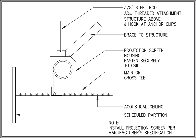
Figure 3-8 Detail drawings
Architectural Drawing Symbols
Each project drawing has different symbols and icons that are used to depict specific elements of the project design or the relationship between multiple drawings, such as where a room depiction in one drawing is continued on another drawing.
Architectural symbols are standardized by country or region, and normally a drawing set will include a legend. As long as they are defined in the legend, the actual object does not matter.
Typical symbols you will see include the following:
• Column lines
• Match lines
• Elevation flags
• Section cut flags
• Detail flags
Column Lines
A grid system, also known as a column line, is used to indicate the locations of columns, load-bearing walls, and other structural elements within the building layout, prior to the room locations being defined. Grid lines are used to reference the schedule and for dimensioning. Vertical grid lines should have designators at the top and be numbered from left to right. Horizontal grid lines should have designators at the right and be alphabetized from bottom to top.
The grid system can be used to find your way around a work site in the early construction phase. Contractors will refer to a point in the space with respect to where it exists on the drawing, as in “4 meters west of B6.” Since the space may not yet be divided into rooms, identifying a point by the grid system ensures that everyone at the site understands the location.
Figure 3-9 illustrates a column line. You should orient the point of the circles to the column line with the letters in one direction and the numbers in the other direction.

Figure 3-9 Column lines
Match Lines
Technicians use match lines (Figure 3-10) to show how each subdrawing matches to another page of the drawing. For example, it may take multiple pages to depict one area of a building. To assemble the separate drawings so you can see the big picture, the individual pieces are aligned using the match lines as a guide. The shaded portion of the line is the side that is considered.
Figure 3-10 Match lines
TIP Remember to include page numbers to identify the adjacent drawing element.
Elevation Flags
Elevation flags (Figure 3-11) are used on plan drawings to indicate related elevation drawings. The picture displayed is an example of an elevation flag. The center number indicates the page number where the elevation drawings can be found. The letters in the triangle portions of the figure identify the elevation drawing on that page.

Figure 3-11 Elevation flags
Each elevation view for a room may be drawn in order and presented in a clockwise manner. This way, you can “look around the room” as if you were standing on the elevation flag and viewing the walls.
Section Cut Flags
Section cut flags indicate which section drawing depicts a section of a master drawing in more detail, as shown in Figure 3-12.

Figure 3-12 Section cut flags
The bottom number indicates the page number where the section drawing can be found. The top number is the section drawing identification, because multiple section drawings may be on the same page. A line extends from the center of the symbol indicating the path of the section cut. The right angle of the triangle is an arrow indicating the view direction of the section drawing.
Section views are similar to elevation views. They depict specific wall sections, based on the section cut line indicators on the master floor plan drawing.
Detail Flags
Detail flags indicate the small items that need to be blown up to show how they need to be installed. These items are too small to draw or see at the project’s typical drawing scale.
In a large system, there may be hundreds of areas requiring more detail to read accurately. Each instance is numbered. The bottom number indicates the page number where the detail drawing can be found. The top number is the detail drawing identification, because multiple detail drawings may be on the same page. In Figure 3-13, the symbol refers to detail number 1, where you can find more information about drawing AV1.06.

Figure 3-13 Detail flags

CAUTION Abbreviations are not the same in all countries.
Common Architectural Drawing Abbreviations
See Table 3-1 for common architectural drawing abbreviations.

Table 3-1 Common Architectural Drawing Abbreviations
The AV Design Package
You can’t design or install AV systems without considering other system designs. Because in the course of your work you will be communicating with members of the architecture, engineering, and consultant teams, refer to the standards of all applicable organizations for guidelines on effective communication.
The AV design package represents a written method of communicating design intent to allied trades. It also conveys architectural details that may impact the AV-enabled environment.
Design documents must include enough information to convey the intent of the AV design. In addition to system design information, certain administrative contract language will form the basis of the actual installation contract. The design package is the basis of most—if not all—of the contract that an AV integrator signs when the project is awarded.
Major components of the design package include the following:
• Administrative front-end specifications
• Architectural and infrastructure drawings
• AV system drawings
• AV system specifications
Watch a video about the components of an AV design package at www.infocomm.org/PackageVideo. Appendix C provides links to all the helpful videos in this guide.
Front-End Documentation
A construction contract typically has an administrative front-end section. This section explains how the contractor and owner will interact by specifying what documentation, meetings, reports, and record drawings are required.
Front-end documentation usually includes the following:
• Invitation to bid This is a cover letter that formally invites potential bidders to respond to the bid package. It includes contract information, dates, times, and schedules associated with the bid process.
• Request for quote (RFQ) This is a statement that invites potential bidders to submit a “resume” of their qualifications for the job.
• Bid response form This organizes responses from potential bidders and indicates what information is required.
• General conditions The architect for the base building contract provides the general conditions. Typical sections of the general conditions include the following:
• Project work conditions and terms
• Definitions of terminology
• Safety and accident prevention
• Permits, regulations, and taxes
• Insurance
• Overall quality control
• Submittals
• Substitutions schedule
• Changes in the scope of work
• Initiating and processing change orders
• Warranty
• Non-discrimination and affirmative action
• Contract termination options
• Arbitration
• Invoicing and payments
• Money matters in the contract Within the general conditions—and sometimes within a consultant’s specifications section—are the terms related to invoicing and payment.
Architectural and Infrastructure Drawings
Architectural drawings indicate where the systems will be installed, what infrastructure exists, and what may be required for AV systems. These indicate available power, signal conduit, data outlets, and structural accommodations for AV equipment.
Architectural drawings provide a technical illustration of all construction details, including the following:
• Site work
• Foundation
• Structure
• Power and lighting systems
• Plumbing
• Sprinklers
• Audiovisual equipment
• Electrical
• Mechanical
• Finishes
• Details
3D Modeling and CAD Drawings
When working on an AV design, you will need to express your needs to various allied trades. For ease of communication, you should present your design in a format that will be compatible with documentation from those allied trades.
Many design firms and allied trades use 3D or solid modeling. Also known as computer-aided design, CAD programs allow multiple trades to communicate their needs and flag possible conflicts. For example, if a light fixture was placed in the lighting plan in the same spot where a loudspeaker was placed in an AV plan, a quick comparison of each trade’s CAD drawings would be the easiest way to spot the conflict.
3D modeling helps establish efficient communication. Changes to 3D-modeled documents are reflected quickly and accurately. In addition, 3D modeling allows engineers to explore a greater number of design iterations during product development. When utilized with building information modeling (BIM), 3D modeling allows for concurrent engineering, whereby engineering and manufacturing processes are enabled simultaneously through shared data.
3D modeling also leads to lower unit costs because of reduced development and prototype expenses. All of these advantages lead to a quality project.
Building Information Modeling
BIM describes a data repository for building design, construction, and maintenance information used by multiple trades on a single project. It includes CAD drawings, as well as information such as bid and contract documents, bills of materials (BOMs), timelines, specifications, price lists, installation and maintenance guides, cable lists, and cable label guidelines.
According to the National BIM Standard, “A BIM is a digital representation of physical and functional characteristics of a facility. As such it serves as a shared knowledge resource for information about a facility forming a reliable basis for decisions during its lifecycle from inception onward.”
As an AV designer, BIM may impact your design in several ways. Most importantly, many of the allied trades you will be working with—especially architects—will probably use BIM. You need to ensure that your documentation is compliant with theirs. Early in the design, get in touch with your project architects and other allied trades. This will keep your design compatible and compliant from the beginning.
Detail Drawings: Custom or Integrated Millwork and Casework
When designing a room that contains audiovisual equipment, be aware of the architectural elements that are commonly used to house such equipment. Two items that fit that classification would be millwork and casework.
Millwork refers to items that are custom-cut for the project, such as moldings or trim. AV designers often design the millwork detail for structures that hold a projection screen in place, for example, as shown in Figure 3-14. As you determine the locations of a projection screen or loudspeaker, you need to ensure that the architectural elements will allow them to be placed in exactly the right spot.
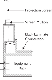
Figure 3-14 Detail drawing showing millwork detail for a projection screen
Casework is similar to furniture, with the distinction that casework is built into the room. Casework includes such items as cabinets, credenzas, benches, and lecterns. There is a range of integration questions associated with the casework that an AV designer will need to help answer, including the following:
• What equipment is expected to be installed in the casework?
• How large should the casework components be?
• What connections are required to interface with the AV system?
• Is the casework adequately sized for the equipment including mounting, cable management, and serviceability?
• What are the electrical and signal connection requirements for the equipment to be installed in the casework?
• What are the cooling requirements, and how will they be implemented?
• Does the casework meet any disabled person codes or requirements?
AV designers often partner with interior designers to create detailed drawings for the custom millwork or casework required to accommodate AV equipment. These drawings communicate to allied trade the exact dimensions, style, shape, color, finishes, ventilation, and so on, that the AV systems require. Therefore, you should understand how to communicate the installation and millwork requirements to the architect. The level of detail required will vary, depending on the project.
AV System Drawings: Facility Drawings
AV system drawings depict the AV system itself. These should reflect equipment configurations, interconnections, details, plate layouts, and other graphic depictions of the system installation. Typical components of the design drawings package include the following:
• Title and index
• Power, grounding, and signal wiring details
• Floor and reflected ceiling plans showing device locations
• System functional diagrams
• Rack elevations
• Custom plate and panel details
• Speaker aiming information
• Large-scale plans, such as equipment or control room plans
• Architectural elevations showing AV devices, their locations, and their relationships to other items on the walls
• Custom-enclosure or mounting details for projectors, microphones, loudspeakers, media players, and others
• Furniture integration details
• Any special circumstances or details that may be required for the installers to understand the design intent
Architectural and facilities drawings are used to perform sightline studies and determine viewing areas, audience listening areas, camera angles of view, and so on.
AV designers use these drawings to coordinate and locate AV elements such as displays, screens, projectors, equipment racks, loudspeakers, specialized lighting, microphones, lecterns, equipment storage, conduit for AV cabling, wall boxes, connection plates, electrical and data receptacles needed for AV equipment, and so on.
AV System Drawings: System Diagrams
Architectural and facilities drawings are used to perform sightline studies and determine viewing areas, audience listening areas, camera angles of view, and so on.
AV designers use these drawings to coordinate and locate AV elements such as displays, screens, projectors, equipment racks, loudspeakers, specialized lighting, microphones, lecterns, equipment storage, conduit for AV cabling, wall boxes, connection plates, electrical and data receptacles needed for AV equipment, and so on.
For the AV system itself, AV designers create system diagrams. These system diagrams could be as simple as a one-line conceptual drawing that shows the system’s intent but not the specific connections. More detailed system drawings show all specific connection points and other important system details. These drawings include the following:
• Video system flows
• Audio system flows
• Control system flows
• Rack elevations
• Connection plate details
• Digital signal processor settings
AV System Specifications
Specifications are sort of like the project’s manual, in that they explain how AV systems should be installed and tested. They describe the system, components, codes, references, and other requirements. They also contain information concerning submittal requirements, shop drawing requirements, components, and system testing requirements.
Now that you have studied all the components of design documentation, take a video tour of the AV design package at www.infocomm.org/DesignTourVideo. Appendix C provides links to all the helpful videos in this guide.
The Basics of AV-Enabled Rooms
AV designers must take a big-picture view of a room to ensure that they understand exactly how it will be used. They also must be able to read blueprints to identify architectural details that may impact AV and communicate those issues to other professionals. For example, room size and how people move in a room will affect design. Keep the following in mind:
• The form of the room should follow the function of the room.
• The number of people in the room will help define the size.
• Circulation and work patterns within the room will help define the form.
All AV-enabled rooms have as their primary function the communication of ideas and information. This concept of a room’s function should be at the center of all design decisions, and all other design characteristics, such as HVAC, lighting, and windows, should be integrated so as to augment the function of the room.
Most AV-enabled rooms include audience, presenter, control, and projection areas. You should also look at other rooms and areas (such as break areas, reception, etc.) to determine whether those spaces might impact the overall performance of the room you’re designing for. In short, work with the architect to ensure that the layout of a room and associated spaces is appropriate for the tasks that will take place in the room.
Audience and Presenter Areas
When planning your room layout, you need to consider both the audience and presenter areas, as shown in Figure 3-15. While there are some considerations unique to each area, many are common to both. The following are some of the commonalities:
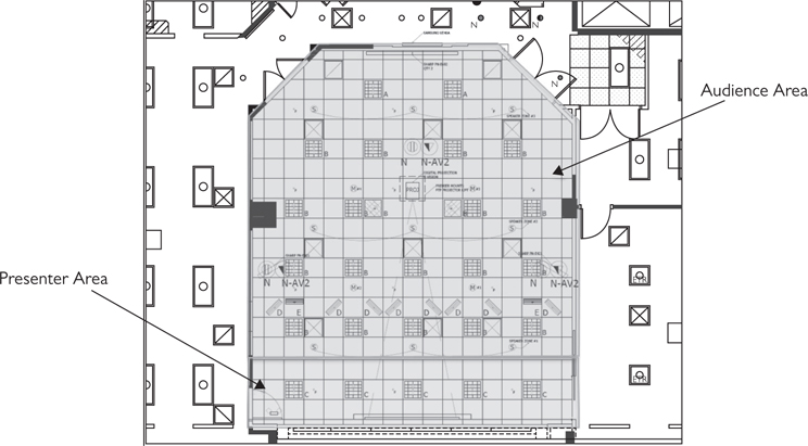
Figure 3-15 Audience a presenter areas in an AV-enabled room
• Equipment and materials Is there enough room for presentation equipment, people’s personal devices, books, and writing materials?
• Connection points Where are AC power, network connections (wired or wireless), and display connections required?
• Comfort What furniture will the room need? Consider ease of movement for both access and egress.
• Sightlines Will everyone be able to see the presenter and their presentation materials?
• Audio coverage Will everyone be able to hear what they are supposed to hear?
When it comes specifically to the presenter area, there are several design considerations you need to address. The presenter area refers to the designated location in a room where presenters (teachers, speakers, etc.) will operate. The area typically includes a lectern, microphones, and a control system interface. The following are some of the design issues to consider in the presentation area:
• Presenter workstation Is the lectern/console well laid out for the range of presentation needs identified by the client?
• Presenter equipment Is there enough room for the presenter and the presenter’s equipment, such as notebook computers or presentation notes? Also keep in mind that a presenter may want to move around during a presentation and not be anchored to the lectern.
• Power, voice, and data Are the power, data, and computer connections in front of the room adequate to meet the needs of presenters?
• Sightlines Specific to the presenter area, can the audience see both the presenter and projected images? For example, if a presenter is too close to the screen, it may be necessary to limit the amount of the lighting on the presenter because ambient light may interfere with a projected image. And if that’s the case, cutting back on light may make it difficult to see the presenter.
• Versatility Have you met all the needs of the client? For example, the client may not want a lectern permanently attached to a specific location. They may intend to move the presenter area to different locations when changing the room orientation to accommodate different audiences. Can they?
Looking out from the presenter area is the audience area—where people sit to take in a presentation. The following are some of the design issues to consider in the audience area:
• Visuals. Can everyone in the audience see the presenter and the presentation? Consider screen size, image resolution, task requirements, sightlines, and more.
• Sound Can everyone in the audience hear the presentation? Consider the acoustics of the room and determine the appropriate configuration of microphones and loudspeakers.
• Ease of movement Can everyone in the audience enter and exit with ease? A properly designed seating layout is essential.
• Audience comfort Will people be comfortable in their seats? Ensure that there is sufficient room between the seats and in the aisles for the required number of persons, given the desired audience seating layout. And be sure to consider the needs of people with disabilities, in compliance with the Americans with Disabilities Act.
Control and Projection Areas
Depending on the size and scope of a room, the AV system may require a dedicated control or projection room. Think of the control/projection room at the back of an auditorium, for example. The design issues associated with a control or projection area are usually technical in nature and include the following:
• Equipment space In some cases, AV operators may be required to support a presentation. Is there enough room for both AV operators and the projection equipment? If an operator is required to remain within the control area for long periods, then the room should be designed to provide an adequate level of comfort.
• Heating and cooling Can the heat generated by AV equipment be removed from the room? Coordinate the design requirements with the architect and HVAC designer to ensure adequate ventilation.
• Power requirements Is there sufficient power for the required equipment?
• Voice and data Does the area include appropriate telephone and data communication? For example, a network cable may be required to ensure computer-based presentations can access required data. Phone communication with the presenter area may also be desirable.
• Task lighting There needs to be enough lighting for operators to see system controls without adversely affecting the quality of a projected image.
• Sound isolation Noise from the area, such as cooling fans, must be controlled and minimized so that it does not distract the audience.
• Monitoring Operators must be able to hear what’s going on in the main room to support the presentation or other activity. They shouldn’t be “tucked away in a closet,” as sometimes happens.

NOTE There are other spaces that support a room, its occupants, and the activities in a building, such as lounges, breakout rooms, reception areas, and restrooms. Often, the design of these associated spaces can impact the success of the rooms an AV designer creates. For example, a reception desk adjacent to the presenter area of a room can be a source of noise that might interfere with the presentations taking place within the room.
Programming
In AV and information technology (IT) fields, the term programming often refers to software coding of programmable devices, such as control systems and digital signal processing equipment. But for other allied trades, such as architects, programming is the process by which the overall requirements for the building are defined. Architects document the needs of the owner and end user as a preliminary step to putting lines on paper that represent the space plan. The architectural program document discusses the facility in terms of square footage, space configuration, and overall quality of the building.
Applying an AV design begins with careful planning and time spent identifying and discussing the end-user’s needs. Therefore, let’s take an in-depth look at this crucial step of the AV design process.
The Needs Analysis
A needs analysis requires identifying the activities that end users need to perform using AV and developing the functional descriptions of the systems that support those needs. Conducting a needs analysis is the most crucial stage of the design process. It determines the nature of the systems, their infrastructure, and the project’s budget.
When you ask a client and the client’s end users why they need an AV system, they may not always know. However, they do know what tasks they need to accomplish to do their jobs. This is where an AV design educates clients and helps fill in the missing information, making connections between jobs tasks and the capabilities of an AV system.
Figure 3-16 shows the needs analysis pyramid, a visual representation of how needs relate to an AV system’s functionality, first through the applications they enable and the tasks they help accomplish.

Figure 3-16 The needs analysis pyramid
But first, it’s important to understand who we’re talking about when we talk about your client’s end users and why you need their input on a project.
Who Are the End Users?
The client is the person paying for the AV system. It might be a business owner, a chief technical officer, or a facilities manager.
End users are people who operate a system day to day. They can be technical end users who know a lot about the system, such as a technology manager or production engineer. Or they can be nontechnical people who need the system to work at the push of a button, such as a teacher or an executive using a conference system. You need to understand the needs of both the person holding the purse strings (the client) and the person using the system (the end user).
End-user input is essential when designing an AV system. The fact is, other client representatives may not really understand how a room and its AV system will be used. Ignore end users at your peril—you’ll hear from them if they’re dissatisfied with the final product.
Asking end users probing questions helps fill in the blanks when determining what they really need. Ask not only what they plan on doing in a space but also how they plan to do it. And depending on who you’re talking to during the needs analysis, figure out who can get you what you need. For example, ask for scale drawings of the space and its surrounding infrastructure. Get a feel for estimated or fixed budgets. And figure out whether there will be any constraints placed on the AV team by the client, such as work hours during the project (i.e., do you have to install systems on weekends?), acceptable ambient noise levels, or what else will be going on in the building at the same time.
Clients on a Project
The actual who’s who of a project team will depend on the size and nature of the project. An AV designer has other project clients, too, including the project manager (if not the architect or a member of the organization for whom the project is being built) and other design specialists.
It is important to identify any differences in approach and opinion among end users, decision makers, funding groups, support groups, and even external contractors, such as project and design team members. The difference between a good and unsatisfactory project outcome can be in the AV designer’s ability to recognize and manage varying expectations.
Some end users may be low in an organization’s hierarchy but have the best knowledge of what an AV system should achieve. Others, with more authority but less understanding, may have different expectations or place constraints on the project, in terms of timing and budget. The AV designer must find ways to communicate with, educate, and understand the perspectives of each stakeholder.
For example, at times, end users will have unrealistically high expectations and ask for functionality (equipment and features) that is not justified by their needs or that are unaffordable based on the available budget. The AV designer has to know when to support end users and argue for better funding and when to recognize that a budget is realistic and help end users appreciate that some of the things they’re asking for are “wish list” items.
The following sections discuss some of the key players you may encounter as you work on your AV design.
The Owner Team
Depending on the type and size of the owner organization, participants may consist of a small number of people or a large group. An owner can be a corporation, a government agency, or an individual. In some cases, the owner of a building is fitting out a space to be leased to another company that is the actual purchaser of the AV systems. Some owner configurations are more complicated, such as in some state university systems, and some are simple, as in the case of a small private company, such as a law firm or a small manufacturer.
The owner typically has its own representatives in the building design process. Representatives range from nontechnical administrative employees to chief executive officers (CEOs) and from facilities managers to in-house architects, if the client owns or leases a lot of property. Sometimes a team or committee represents the owner. The owner team can include one or many of the following types of people.
End Users
As noted earlier, end users are the people who will ultimately use the AV systems and the spaces where they will be installed. It is important to note that end users may not be employed by the owner’s organization, although in most cases they are. In addition, later mentions of the owner may or may not represent the end users, depending on the structure of the project.
In terms of AV systems, there are generally two types of end user.
• Technical end users In the AV industry, technical end users, also known as technology managers, are responsible for operating, setting up, maintaining, scheduling, and managing an AV system. Most are familiar with the IT network and how the AV systems relate to it; some are also responsible for the IT systems.
• Nontechnical end users They are sometimes referred to as the “real” end users. These are the presenters and meeting participants who use AV systems for their intended purpose: information communication. These may be teachers, trainers, students, salesmen, CEOs, or anyone who participates in an event that utilizes an AV system.
Facility Managers
Larger organizations have a facility manager heading up a department that covers everything from janitorial services to renovation work and from planning to operations. Facility managers are concerned with physical facility standards (standard finishes, cabling schemes, and electrical/mechanical services) and construction schedules from the owner’s operational perspective. Their areas of AV concern may include space allocation, cabling standards, and installation schedules because large AV installations often overlap with occupancy periods, after a general contractor has finished its own work.
AV Department Manager
Many organizations have someone on staff who manages the current AV systems, schedules usage, and maintains the AV spaces. The AV manager usually coordinates training for end users once the system has been installed. The AV manager may also act as the owner’s representative or point of contact throughout the AV project.
Smaller organizations may not have a dedicated AV position. In that case, responsibility often rests with someone who has similar experience or expertise, often in the IT department.
Buyer, Purchasing Agent, or Contract Representative
Medium to large organizations often have a department or individual whose role is to manage contracts, select vendors, and establish or negotiate contract pricing and terms. These personnel may be involved in the construction document preparation (particularly the administrative portions), the bidding and contract negotiation processes for designers and installers, and the administration of billing, paying, and contract close-out tasks.
Conducting the Needs Analysis
Now you know who is involved in the needs analysis. Next you’ll talk to stakeholders, review existing documentation, evaluate the site environment, conduct program meetings, and write the program report. That’s a lot, but each step is important. We’ll break them down.

Step 1: Ask Questions
First, you’ll talk to as many stakeholders as feasible. Knowing that there are many ways clients can use AV, how can you find out what they need so you recommend just the right solution? Just ask. But ask in the right way.
When you create a good dialogue with a client and a client’s end users, everyone will better understand the project’s goals. Good dialogue is also friendlier and less threatening.
Questions foster dialogue. Questions also help gather important information, get the client involved, and persuade more effectively (and softly) than statements. Use them often and intelligently. When asking questions, employ the following:
• Open-ended questions
• Closed-ended questions
• Directive questions
When you want the client to give a full, informative response—or just start talking—ask open-ended questions that are hard to answer in a word or two. Here are a few examples:
• How do people in your organization like to present content in meetings?
• What kinds of meetings are held in this facility?
• How would you describe the current effectiveness of your training?
• What would you like to see be done differently or better?
Answers to questions like these tell you how your client thinks, how much they know, and what they consider important. If you need factual or specific information, ask closed-ended questions, such as the following:
• How many people will the room need to seat?
• Are there any windows or columns in that room?
• When do you expect construction to start?
When it’s time to bring a client to your point of view or persuade them that one of your ideas will work well, ask directive questions. These are questions that suggest their own answer—sometimes the one you want to hear—such as the following:
• Can you see the added value of a maintenance agreement to protect your equipment investment?
• Wouldn’t it be great if everyone knew how to take full advantage of this room?
• Would you get more use out of the liquid crystal display (LCD) display or the projector and screen?
Step 2: Review Existing Documentation
Once you’ve talked to key stakeholders, your next step is to gather and review the available documentation. This documentation is usually available with information about the existing physical, organizational, and technical aspects of the project.
Ask the client for the existing documentation. It may include items such as scale and engineering drawings (blueprints, CAD drawings), architectural program documents, organizational project directories, design manuals, standards, best practices, and other owner and end-user information. Ensure that you have a full set of drawings for the rooms your AV design will address. Be sure to examine all elements that might potentially affect the layout, mounting, installation, and operation of AV system components. If no documentation is available, you may need to create new material based on existing conditions.
At this point, it’s also important to ask the client about budget. Providing a fixed budget and setting expectations will go a long way toward addressing concerns the client may have. Be sure to ask which part of the budget is for AV and which part is for other contractors’ work. The customer may not be aware that other trades share in the project.
Step 3: Evaluate the Site Environment/Benchmarking
If the AV systems are to be installed in an existing facility, it is important to tour those areas during the needs analysis process to gather information about physical characteristics and how the spaces are currently being used. It is important to learn about any issues that may impact your ability to work at the client site once the design and installation tasks begin, such as building security and access. In many cases, the design and installation teams can identify a method to work around constraints, such as working during certain hours or in areas where they are less likely to disrupt operations.
When touring and evaluating an existing facility’s environment for the first time, make note of room elements such as the acoustics, lighting, and electrical infrastructure. Use handheld light meters and audio analyzers for quick, useful measurements. Getting an idea of the ambient light levels could inform future contrast ratio decisions, and ambient noise readings can give you a ballpark idea of audio reinforcement needs. You’re not trying to make a detailed analysis; you’re just getting to know the space.
You should also consider visiting other similar facilities for review and comparison. This is known as benchmarking and gives the owner and the design team a common (and sometimes expanded) vision of what the user wants and needs. Seeing a number of locations of similar size, type, and usage establishes a benchmark or guide on which to base the new facility design.
Benchmarking offers the following benefits:
• It provides an opportunity to see varying approaches to design versus budget.
• It may inspire new design ideas.
• The team can identify successful (and unsuccessful) designs and installations similar to the project at hand.
• It can help determine which functions and designs are most applicable to the current project.
• It allows stakeholders to establish a communication path with other building managers and end users about what they learned in the design and construction process and to discuss what they would do the same or differently if they needed to do it over again.
Benchmarking can’t occur on all projects. Sometimes you can save the time and money required to visit similar sites by letting the client look through a portfolio of your firm’s work on similar projects or by asking them to provide you with pictures of projects they’ve seen and liked.
Step 4: Conduct Program Meetings
Once you’ve collected feedback from stakeholders, reviewed existing documentation, and evaluated the environment, you can schedule program meetings.
Program meetings should include representatives of both the design team and the owner. During these meetings, the architect, AV professionals, and other design team members discover more about the end-users’ needs by examining required applications and the tasks and functions that support those applications. In other words, you’ve learned what they want; now you’re discussing in-depth how they’ll get it. If you don’t know who you should be meeting with, go back to the section “Clients on a Project.”
As you already understand, one or more people will use the AV system you design. Others may manage or maintain it. And still others may pay for it. So, it follows that some will care about functionality, others about upkeep, and others about cost. A safe way to find out how decisions will be made during program meetings is to ask your contact, “Who, in addition to you, will be involved in this decision?” Words are important: You don’t want to suggest that your contact has no authority.
A good follow-up question might be, “What is their primary interest or concern?” This will help you target your message to each stakeholder based on what they care about most. Yes, they all care about the whole project, but they also have their own areas of focus: operations, security, maintenance, financing, and so on.
Here’s another good question for a program meeting: “How far along are you in your budgeting process?” This asks in a nonthreatening way whether the client has a realistic budget in place or they’re able to make the investment a certain design decision may require. It’ll also help you learn more about the client’s planning and decision-making processes.
AV solutions are often—although not always—scalable to a client’s needs and budget. But it’s unsafe to guess about expectations because you will usually guess wrong. Not only does this waste your time and theirs, it can create hard feelings and damage relationships. The basic rule is never guess about what you can find out for sure by careful questioning.
TIP In each meeting with your client, make it a point to learn who else has an interest in AV and look for opportunities to meet them. Never go around your contacts or over their heads. Offer to arrange meetings and introductions between your colleagues and theirs. Naturally, each meeting needs a purpose; it can’t only be something nice to do.
Step 5: Write the Program Report
At the conclusion of the program meetings, information is captured in a written report of the findings, including an interpretation of the users’ needs with respect to the AV systems. The report should include a conceptual system description, along with necessary information about its impact on spaces that have already been programmed, designed, or built.
The program report is a functional description of the system that your design team intends to deliver. It functions as your project’s scope of work, in that it contains the milestones, reports, deliverables, and end products that you agree to deliver to the project customer. It should also lay out change order, escalation, sign-off, and payment procedures. Many designers will also include a list of equipment in the program report because it helps with the cost estimation, though a program report should contain much more information than a simple bill of materials.
The objectives of the program report are as follows:
• Communicate to decision makers about the overall systems and budget
• Communicate to users the system configurations that would serve their needs as identified during the program meetings
• Communicate to the design team a general description of the AV systems and what impact they may have on other trades
• Communicate the scope and functionality of the AV systems to be designed and installed
NOTE A scope of work can describe many elements of an AV project, including aspects of the design, such as the program report. The scope of work is often the most comprehensive description of the project and may include any or all of the following: information about all contractors, a description of the solution (with drawings and products), key assumptions, pricing, project milestones, responsibilities, project-management procedures, warranty information, and terms and conditions.
A Closer Look at the Program Report
At the conclusion of the program meetings and needs analysis process, you need to document what you learned in what is called a program report. This nontechnical document describes the client’s needs, the AV system’s purpose and functionality, and your best estimate of probable cost, and it ultimately documents the client’s approval.
NOTE Other names for the program report include AV narrative, discovery phase report, return brief, or the concept design report.
What follows are the common contents of a program report. Exact contents will vary because every project is unique.
• Executive summary This section provides an overview of the project, the programming process, systems, special issues, and overall budget.
• Space planning This section provides advice to the design team, where necessary, about the space requirements of AV systems. This may include equipment closets, projection rooms, observation rooms, internal room layouts, room adjacencies, and so on.
• System descriptions This section is a nontechnical description of the client’s desired functionality for each system. It may include AV sketches, drawings, diagrams, photos, product data, and other graphics, such as touch-panel interfaces, to illustrate the capabilities of the proposed systems.
• Infrastructure considerations This section describes the electrical, voice, IT, mechanical, lighting, acoustic, structural, and architectural infrastructure needed to support the AV systems.
• Budget recommendations This section outlines the probable costs to procure, install, and commission the proposed AV systems, as well as any additional costs, such as tax, “builders work in connection” (BWIC), markups, service, support, and contingencies.
Once the document is distributed to stakeholders, reviewed, and approved, it becomes the basis for the upcoming design phase. The review and approval process may go through several rounds before obtaining client or end-user sign-off.
NOTE Your program report will vary from project to project. There is no single correct way to order the information, but using the list of items outlined in the ANSI/INFOCOMM 2010-2M Standard as a table of contents is a reasonable starting point.
AV Budget Terms
As noted earlier, the program report should include an opinion—or estimate—of how much the AV system will cost. As you form your opinion, pay attention to the following budget terms. Using them incorrectly may lead to confusion and financial consequences later in the project.
Opinion of Probable Cost
This term describes an early attempt to determine the cost of a system before there is enough detailed design to produce a line-item estimate. The opinion of probable cost is an “educated guess” based on experience and some line-item costs for large equipment, such as projectors or large-matrix switchers. Final costs cannot be applied until the system is designed and the actual equipment selected.
Estimate
An estimate implies that there is a more objective basis for the cost provided. It is an “approximate calculation” that includes a line-item analysis of equipment and labor (perhaps including taxes and other ancillary costs); it would be more accurate than an opinion of probable cost.
Quote
A quote is a detailed and enforceable estimate. It should be provided and identified as such only if it’s based on a program report and an AV system design. If it isn’t, the client, the end users, and the AV provider are at risk of a painful mismatch of needs, capabilities, and cost.
Budget
Although the term budget is often used in the context of terms described earlier, by strict definition it applies only to what the owner or project team has allocated for a particular system, trade, or facility. In the correct relationship of these terms, the budget should be established based on an opinion of probable cost or an estimate. A quote is then submitted by a provider based on a Request for Proposal (RFP). The quote is subsequently compared to the budget before acceptance by the owner.
Distribution and Approval
A program report may contain sensitive information. It should be distributed on a need-to-know basis and never to anyone outside the project team without permission from its writer and the client (or authorized representative). Distribution to unauthorized parties could reveal confidential information about the client, project, or other details. In particular, it should not be distributed to individuals and organizations with connections to the AV industry. Doing so could undermine the competitive bid process or a project where an integrator is not already engaged. Apart from leaked cost information, which could potentially affect the owner, unauthorized distribution of the program report opens a door to suppliers and others inappropriately lobbying project team members and/or manipulating prices.
Watch a video about writing a program report at www.infocomm.org/ProgramReportVideo. Appendix C provides links to all the helpful videos in this guide.
Assuming you distribute the program report to the appropriate parties, you need to establish a set period of time for comments and responses. At its conclusion, any necessary revisions should be made and the report either redistributed or submitted for approval if only minor changes were required. Depending on the nature of the feedback, more program meetings may be required to address any major issues or deficiencies.
Once the program report is signed and approved, it can be used as the basis for the design of the AV systems and their supporting infrastructure. In this formalized, approved state, it protects the owner, consultant, and designer by ensuring everyone defines the project in the same, unambiguous way.
Chapter Review
In this chapter, you learned about the phases of an AV design project, including the program, design, construction, and verification phases. You also learned about what goes into an AV design package, including drawings and diagrams. AV designers must be able to read and interpret such drawings and diagrams to collaborate with other professionals on an AV project.
Perhaps the most important part of the AV design is the needs analysis, which occupies a significant chunk of the program phases. Being able to discern the various stakeholders on a project and illicit information about their needs and wants is critical to designing the best possible AV system to meet those needs and ensuring it delivers as promised. All the documentation that comes out of the program phase will serve to guide the project to its successful completion.
Review Questions
The following questions are based on the content covered in this chapter and are intended to help reinforce the knowledge you have assimilated. These questions are not extracted from the CTS-D exam, and they are not necessarily CTS-D practice exam questions. For an official CTS-D practice exam, download the Total Tester as described in Appendix D.
1. What is the primary goal of a needs assessment?
A. Identifying the intended use of a space
B. Selecting the right equipment
C. Establishing the “first use” date
D. Meeting the budget requirements
2. The total length of a measurement from a metric (SI) scaled drawing of 1:50 is 100 mm. What is the actual length?
A. 5 meters
B. 50 meters
C. 0.5 meters
D. 150 meters
3. Which of the following architectural drawing symbols is a detail flag?
A. ![]()
B. 
C. 
D. 
4. The total length of a measurement from a U.S. customary scaled drawing of 1/8 inch is 3.5 inches. What is the length of the real object?
A. 18 feet
B. 25 feet
C. 28 feet
D. 35 feet
5. What type of drawing would you use to find out exactly how the projector should be mounted to the ceiling?
A. Reflected ceiling plan
B. Mechanical drawing
C. Detail drawing
D. Section drawing
6. Which abbreviation on a drawing tells you that you will not need to install a specific display screen?
A. OFOI
B. OC
C. OD
D. NTS
7. Technical end users are sometimes referred to as:
A. Teachers
B. Technology managers
C. Clients
D. Architects
8. Which is the following is not a step in conducting a needs analysis?
A. Review existing documentation
B. Evaluate the site environment
C. Conduct program meetings
D. Educate allied trades
9. Benchmarking is a process by which AV designers and clients:
A. Evaluate the performance of AV systems
B. List specifications required on AV equipment
C. Examine the AV designs of other facilities
D. Compare expected results to actual results
10. Which of the following would not be considered part of the system drawings for an AV design?
A. DSP settings
B. Rack elevations
C. Control system flows
D. Color schemes
Answers
1. A. The primary goal of a needs assessment is to identify the intended use of a space.
2. A. When the total length of a measurement from a metric (SI) scaled drawing of 1:50 is 100 mm, the actual length is 5 meters.
3. C. Figure C shows a detail flag.
4. C. When the total length of a measurement from a U.S. customary scaled drawing of 1/8 inch is 3.5 inches, the length of the real object is 28 feet.
5. C. You would use a detail drawing to find out exactly how a projector should be mounted to the ceiling.
6. A. OFOI (which means “owner furnish, owner installed”) on a drawing would tell you that you will not need to install a specific display screen (or other OFOI equipment).
7. B. Technical end users are sometimes referred to as technology managers.
8. D. Educating allied trades is not part of the needs analysis.
9. C. Benchmarking is a process by which AV designers and clients examine the AV designs of other facilities.
10. D. Color schemes would not be considered part of the system drawings for an AV design.