
CHAPTER 19
Conducting Project Implementation Activities
In this chapter, you will learn about
• The audiovisual performance verification process, including for discrete audio and video systems
• Troubleshooting methods
• The verification standard for system closeout
• Closeout documentation
• Customer training
• Obtaining customer sign-off
As the AV industry establishes standards and best practices on and off the job site, owners, consultants, and integrators will need to conform to the standards and follow the guidelines for the proper design, fabrication, installation, and integration of AV systems. In this chapter, you will learn about the system performance verification standard and resources provided by several organizations. You will also learn how to troubleshoot common problems.
For starters, you should familiarize yourself with various AV-related standards. This is an excellent time to verify that the system that was installed is compliant with all relevant standards. You will also need some specific test and measurement tools for calibration and verification of both audio and video.
Your knowledge of the basic principles and theories involved in electronics, audio, video, and networking technologies will be well utilized during the final stretch of AV system integration. Once you have studied the theory and conducted verification of the system on the job site, you will be able to set up and verify new AV systems with confidence.
Performance Verification Standard
The ANSI/INFOCOMM 10:2013 standard, Audiovisual Systems Performance Verification, can help determine whether an AV system has met your client’s objectives and is performing to design expectations.
Benefits of using this standard include the following:
• Streamlining verification tests and reporting
• Providing a verifiable outcome
• Creating a common language between all parties
• Aligning outcome and performance expectations at an early stage in the project
• Creating reporting that completes the project documentation
• Reducing project risk through early identification of problems, thereby reducing the likelihood of remedial work
This standard should be used in conjunction with ANSI/INFOCOMM 2M-2010, Standard Guide for Audiovisual Systems Design and Coordination Processes, as well as other relevant performance standards. The 2M standard provides a framework and supporting processes for determining elements of an audiovisual system that need to be verified, the timing of that verification within the project delivery cycle, a process for determining verification metrics, and reporting procedures. The standard includes 160 reference verification items.
As shown in Figure 19-1, verification of conformance to the 2M standard must include the delivery of the Audiovisual Systems Design and Coordination Processes Checklist.

Figure 19-1 Title block of Audiovisual Systems Design and Coordination Processes Checklist
The 2M standard serves to verify the following:
• Documentation of applicability An outline that indicates which sections of the standard are applicable to the project according to contractual agreements, as well as any services not applicable (indicated as N/A)
• Consideration Written verification that the service providers have read and understand this standard and agree to be referred to as the Responsible Party for the applicable sections
• Completion Written verification that the service providers have completed the approved services, indicated by the party authorized to sign as Accepted By
The verification can be as simple as checking off boxes when you complete a task. By documenting your work along the way, you are setting yourself up for success when you hand over the system to the client.
The Audiovisual Systems Design and Coordination Processes Checklist includes three check boxes for each item for the project team to address.
• The Activity Code This identifies the type of item, such as deliverable (D), coordination (C), task (T), meeting (M), other (O), or not applicable (NA).
• The Responsible Party This is the designer, contractor, or integrator who is delegated and contracted to perform the activity. This may be more than one party and should be identified as such.
• Accepted By The client, designer, contractor, or integrator who is authorized and contracted to verify that the activity has been performed. This may be more than one party and should be identified as such.
Figure 19-2 provides an example of how a checklist line item could be filled out. The task is “schedule and agreement for meetings.” This is an activity code M, C, and D, which stands for “meeting, coordination, and deliverable.” The integrator has been contracted to perform the activity, and the consultant is authorized to verify that the activity has been performed.

Figure 19-2 A sample checklist line item filled out in accordance with the Standard Guide for Audiovisual Systems Design and Coordination Processes
System Verification Process
The performance verification process involves many phases, starting with pre-integration and all the way through final acceptance by the client, as shown in Figure 19-3. The actual testing of system performance starts with turning on the system for the first time and ends with handing off the remotes and documentation to your client. Therefore, it starts in the middle of a typical AV project, after planning, fabricating, and installing the equipment at the job site.

Figure 19-3 Performance verification phases and milestones
The verification process in each of the phases is as follows:
• Pre-integration verification Refers to items that take place prior to systems integration. These items will generally verify existing conditions, such as the presence of device enclosures, or items such as backing/blocking/framing that require coordination among the trades for AV system installation.
• Systems integration verification Refers to items that take place while the audiovisual systems are being integrated or built, including off-site and onsite work. These items will generally verify proper operation or configuration so that the system can function (for example, equipment mounted level, phantom power, termination stress, AV rack thermal gradient performance).
• Post-integration verification Refers to items that take place after the audiovisual systems integration has been completed. These items will generally verify system performance against verification metrics as defined in the project documentation (for example, projected image contrast ratio, audio and video recording, control system automated functions).
• Substantial/practical completion verification Indicates conditional acceptance of the project has been issued by the owner or owner’s representative, acknowledging that the project or a designated portion is substantially/practically complete and ready for use by the owner; however, some requirements and/or deliverables defined in the project documentation may not be complete. This milestone occurs at the end of the post-integration verification phase.
• Closeout verification Refers to items involved with closing out the project. These items will generally be related to documenting the As-Built/As-Is status of the systems and transfer of system software, among other items such as control system test reporting, As-Built drawings complete, and warranties.
• Final acceptance verification Indicates that acceptance of the project has been issued by the owner or owner’s representative, acknowledging that the project is 100 percent complete; all required deliverables, services, verification lists, testing, performance metrics, and sign-offs have been received; and all requirements defined in the project documentation have been satisfied and completed that occur at the completion of the closeout verification phase. No further project activity will take place after this milestone is verified.
Certain verification items may need verification at multiple times during a project. The reference verification items provided in the ANSI/INFOCOMM 10:2013 standard, Audiovisual Systems Performance Verification, define the verification phases at which those items should be tested. Where additional items are added on a project-specific basis, they will also be allocated a verification phase.
Regional Regulations
You need to know how codes, regulations, and safety procedures apply to your job site. To do that, you need to identify in the location of your project the authority having jurisdiction (AHJ) or the regional regulatory authorities, as they are known in some areas of the world. These organizations typically monitor compliance with codes and laws. Standards and best practices are typically established by organizations consisting of representation from various sectors of the industry.
Codes and laws are mandated methods, practices, and collections of standards that are enforceable by law. You can be legally punished for not following them. Generally, an inspector will be present to verify that the work is being done according to code. Each jurisdiction may have its own set of regulations.
If you encounter conflicting codes, follow the most restrictive code for the region in which they are working. In other words, if you find the interpretations of applicable codes and standards are in conflict, follow the requirements of the more stringent code or standard.
Standards are documents that provide requirements, specifications, guidelines, or characteristics that can be used consistently to ensure that materials, products, processes, and services are fit for their purpose. They are often prepared by a standards organization or group and published with an established procedure.
Best practices are the best choice of the available methods for accomplishing a specific task in an industry. Best practices are recognized as the proper way to do a certain task. They can be a generally accepted industry practice or unique to a specific company.
Resources for Regional Codes
As noted earlier, codes, regulations, and safety procedures vary by location. You will need to check these for the area of your project. Several organizations provide resources to locate regional or industry-specific codes.
The National Electrical Code (NEC) is an electrical wiring code for the United States, and there are similar organizations in countries around the world. The NEC provides comprehensive information including the following resources:
• The NEC Codebook provides the detailed and comprehensive descriptions of electric standards. The codebook is usually used as a reference by individuals interested in the details affecting an electrical system installation.
• The NEC Handbook provides the complete electrical code, along with extensive additional commentary. The commentary includes drawings, additional articles, wiring diagrams, tables with supplementary data, and photographs to provide a better understanding of the NEC’s requirements.
There are many different codes and standards that apply to various regions in the world. Every country has its own resources for standards. If you need to access standards by your region or industry, you can begin by searching the following two websites:
• The International Organization for Standards (http://iso.org) publishes standards to ensure that products and services are safe, reliable, and of good quality. For business, they are strategic tools that reduce costs by minimizing waste and errors and increasing productivity. The ISO has technical committees working on standards for a large number of industries.
• NSSN (http://nssn.org), administered by the American National Standards Institute (ANSI), is a search engine that provides users with standards-related information from a wide range of developers, including organizations accredited by ANSI, other U.S. private-sector standards bodies, government agencies, and international organizations.
Verification Tools
You’re not necessarily an installer, but during pre-installation preparations, your team should have developed a verification checklist; revisit it to make sure you or someone on the team has the tools for calibration and verification of audio and video signals listed in Table 19-1, including general items such as crimpers and tape. In addition, you may want to use software-based signal analyzers for some of the components in your design. Note that Table 11-1 does not provide an exhaustive list; you may have more tools that are specific to certain work on various projects.

Table 19-1 Test and Measurement Tools for AV System Verification
Audio System Verification
The audio system can be one of the most challenging aspects of an AV system design. It can be challenging to ensure a system provides an undistorted, high-quality signal with adequate levels to all specified destinations.
An audio system requires final adjustment after all the components have been installed for it to produce the desired or specified volume and quality. It is part of your job to set the audio gain and system equalization (EQ) and to adjust the various digital signal processing (DSP) components for the system to sound as good as it possibly can.
You will need to verify the performance of many components in an audio system and at many points along the signal path. You will want to use the ANSI/INFOCOMM 10:2013, Audiovisual Systems Performance Verification standard. The list of verification items found in that standard will make it easier for you to document the status of the AV system and to keep track of what you and your team have already inspected.
Audio-Testing Tools
You will need to use different test instruments to measure and verify various aspects of the audio signal along its path from microphone or other audio source to the loudspeakers. Audio-testing tools range from handheld devices to computer software programs; some are available for single-function testing and others for testing multiple functions.
Piezo Tweeter
A tweeter is a special type of loudspeaker, usually horn- or domed-shaped, that produces audio frequencies in the range of 2,000 Hz to 20,000 Hz (which is considered to be the upper limit of human hearing). Special tweeters can deliver high frequencies up to 100 kHz.
A piezo tweeter contains a piezoelectric crystal coupled to a mechanical diaphragm. An audio signal is applied to the crystal, which responds by flexing in proportion to the voltage applied across the crystal’s surfaces, thus converting electrical energy into mechanical.
The conversion of electrical pulses to mechanical vibrations and of returned mechanical vibrations back into electrical energy (transduction) is the basis for ultrasonic testing. The active element is the heart of the transducer as it converts the electrical energy to acoustic energy, and vice versa.
Audio Signal Generators
An audio signal generator is a piece of test equipment that produces calibrated electronic signals intended for the testing or alignment of electronic circuits or systems.
As shown in Figure 19-4, audio signal generators generate sine, square, or other waves at specific frequencies or combinations of frequencies. Many signal generators also generate pink noise, a quasi random noise source characterized by a flat amplitude response per octave band of frequency, and white noise, a sound that has the same energy level at all frequencies. In addition to showing frequency sweeps, these devices can also be used to test for polarity.
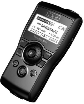
Figure 19-4 A signal generator
Sine waves are used as good, steady references for setting signal levels and to reveal distortion added by the equipment being evaluated. Common sine wave frequencies used include the following:
• 1 kHz Used for setting levels and setting system gain using the unity gain method
• 400 Hz Used in conjunction with a piezo tweeter to listen for clipping, as well as setting system gain using the optimization method
With the right software or app installed, a quality audio interface, and a properly calibrated signal, you can also use your computer, tablet, or smartphone as a signal generator. A tone generator creates a stable, constant signal that can be measured by a signal analyzer set to, for example, a 1 kHz signal at 0 dBu. This establishes the baseline measurement for setting gain.
Sound Pressure Level Meters
Sound pressure level (SPL) is a measurement of all the acoustic energy present in an environment. It is typically expressed in decibels (dB SPL). Sound pressure refers to the pressure deviation from the ambient atmospheric pressure caused by the vibration of air particles. Sound pressure level refers to that variation of level above and below ambient atmospheric pressure and is referenced to 20 µPa or 0.0000204 dynes/cm2, the threshold of human hearing. Sound pressure levels are expressed in decibels to correlate with the human perception of changes in loudness.
An SPL meter gives a single number measurement of the sound pressure at the measurement location. The meter consists of a calibrated microphone and the necessary circuitry to detect and display the sound level. Its function is simple; it converts the sound pressure levels in the air into corresponding electrical signals. These signals are measured and processed through internal filters, and the results are displayed in decibels, as shown in Figure 19-5.

Figure 19-5 Meters for measuring sound pressure level
When selecting an SPL meter, you want to use one that can take accurate readings. Sound pressure level meters are classified based on the allowable tolerances of the measurement. Devices that are not classified do not conform to a standard, so they are not reliable for measurement and testing purposes.
• Class 0 A lab reference standard. It has the strictest tolerances and is used when extreme precision is needed.
• Class 1 For precision measurement. It is useful for taking flat, engineering-grade accuracy measurements instead of wide-range or field measurements.
• Class 2 For general-purpose use. It has the widest tolerances with respect to level linearity and frequency response. Class 2 meters are required only to have A-frequency weighting. Other weightings are optional. For many audio purposes, a Class 2 meter is acceptable.
• Class 3 Intended for noise surveys. It is a simple sound level meter meant to determine whether a noise problem exists. If a problem does exist, further diagnosis will require a higher class meter.
Always reference the project specifications for the SPL meter settings necessary for proper verification. If the verification requirements do not specify settings for the SPL meter, you can use SPL meter weighting guidelines to select one.
You can apply weighting to the SPL meter measurement to correlate the meter’s reading to how people perceive loudness. Figure 19-6 shows how loud different frequencies must be for the human ear to perceive them as equally loud as another. The dotted curve represents the threshold of human hearing, which is what the human ear perceives using a 1 kHz reference. The x-axis of the graph shows actual frequency, and the y-axis shows actual decibels SPL. A 40 Hz tone must be about 50 dB SPL louder before the human ear can perceive it equally as loud as 1 kHz. A 200 Hz tone, however, would have to be only 15 dB SPL louder to be perceived equally as loud as the 1 Hz tone. It is an absolute value, using 0 dB SPL as a reference.

Figure 19-6 Equal loudness curve
The weighting curve represents standard filter contours designed to make test instruments approximate the response of the human ear. Therefore, the different weighting curves are meant to represent what the ear hears at various intensity levels. These measurements are a relative value and depend on where or what you are referencing for your measurement. The SPL meter will typically have three weighting settings: A, C, and Z (for zero).
• A weighting Setting commonly used for environmental, hearing conservation, and noise ordinance enforcement. It closely reflects the response of the human ear to noise and its relative insensitivity to lower frequencies at lower listening levels.
• C weighting More uniform response over the entire frequency range.
• Z weighting No filtering. This is referred to as flat or Z (zero) weighting. A meter may be equipped with settings for A, C, and Flat or settings for A, C, and Z. Flat and Z would be unweighted settings.
You can see the differences in SPL weighting by examining the weighting curves. The line marked A in Figure 19-7 represents the A-weighted filter setting on an SPL meter. You can see that A weighting discriminates against low-frequency energy. The A weighting curve is almost the inverse of the equal loudness curve at a low listening level. The human ear perceives low-frequency energy as a lower decibels SPL than it actually is. The energy is still there; you are just not as sensitive to it at these listening levels. The A weighting reflects that perception.

Figure 19-7 SPL weighting curves
A weighting is useful in situations with low listening levels, including most speech applications. It lowers the decibels SPL reading of low-frequency sounds to reflect how a human being perceives those sounds. As the listening level increases to 85–140 dB SPL, the human ear response “flattens out.” You may then choose a C-weighted filter (indicated by the line marked C in Figure 19-7), whose curve is far less steep.
For example, because they reflect the response of the human ear at low listening levels, A-weighted measurements are frequently used to quantify ambient background noise. While there are better metrics for quantifying background noise levels and their effects on the listener, an SPL measurement provides a simple one-number rating.
The ANSI/ASA S12.60 standard shows that maximum one-hour SPL levels, including those from building services such as heating, ventilating, and air conditioning (HVAC), should not exceed 35 db SPL A-wtd (weighted) for spaces not exceeding 20,000 square feet (566 square meters) in classrooms and other learning spaces.
Given the maximum background noise level of 35 db SPL A-wtd from the standard and that a space should have a minimum 25 dB signal-to-noise (S/N) ratio acoustically, a goal of speech level is at least 60 db SPL A-wtd. However, a sound reinforcement system for speech may more typically operate in the range of 70 to 75 dB SPL.
In addition to choosing a weighting for your SPL meter, you will need to select a response time. A fast response is used for capturing transient, momentary levels. A slow response will capture consistent noise levels. This is useful for averaging rapid fluctuations in sound pressure levels and more closely mimics the way your ears react.
A system may need to be compliant with a specific standard. Internationally, sound level meter performance falls under two different standards: International Electrotechnical Commission (IEC) and ANSI. The IEC standard relates to frontal incidence correction, while the ANSI standard relates to random incidence correction. In other words, does the microphone have to be oriented directly on an axis with the noise source or can it be off the axis up to a certain point? These two different standards relate to response rather than weighting.
Multimeter
Since electronic audio signal levels are typically measured in decibels or decibels to volt, both of which are referenced to a known voltage, an alternating current (AC) voltmeter or multimeter can be used to measure or set signal levels. You can also use a multimeter for testing signal continuity, measuring voltage, measuring DC voltage to test equipment batteries, and measuring signal levels.
When selecting a multimeter, look for the true “root mean square” (RMS) feature, which will enable you to measure the RMS value of an AC voltage. RMS, rather than peak voltage, is the conventional measurement most often used to compare voltage readings in audio applications. The meter must also have wide enough bandwidth to accurately measure the reference signal.
Measurement Microphone
A test and measurement microphone is used to accurately capture system performance. It should be omnidirectional, have a flat on-axis frequency response, and have a preferred-capsule diameter of 1/2 in (6.35mm). The microphone should also give consistent results.
Oscilloscope
An oscilloscope is a test device that enables measurement and evaluation of electronic signals by displaying a waveform. In audio system verification, an oscilloscope may be used to identify clipped sine waves when using the optimization method for setting system gain.
Now that you have a foundation in the properties of audio-testing equipment, you can apply this theory to testing and evaluating the audio signal pathway and listening environment.
Video System Verification
Ensuring appropriate signal levels across all video equipment, adjusting video cameras and displays, and checking audio/video synchronization are all part of the video verification process. As you close out a project, you should test and verify several items using the Video System Performance Verification Items and the Audio/Video System Performance Verification Items from the ANSI/INFOCOMM 10:2013, Audiovisual Systems Performance Verification standard.
Verifying the Video Signal Path
When verifying a video system, you first should check the wiring and cabling of the video equipment. Once all connections have been completed, verify that the wiring methods and cable pathways are correct. This is typically a visual inspection process because you will compare the technical drawings, such as a signal flow drawing, against what you discover in the rack and elsewhere.
As with audio system wiring, during the inspection process, you need to look for the following:
• Correctly terminated connectors. Look for defects such as bent pins or frayed shields.
• Correctly connected cables. They should be attached to terminals as indicated on your system drawings.
• Cabling in the pathways that are properly organized in the walls and in the ceiling. Also, check for proper bend radius at all junction and pull boxes.
As you work through this process, record any errors or discrepancies for immediate repair. Permanent changes that occurred during installation should be documented and submitted to the designer for updating.
Signal Extenders
When distributing signals, cables attenuate the signal over distance. The longer the cable, the more the signal will be attenuated. In some cases, you may elect to use a balun to convert between a balanced signal and an unbalanced signal. A balun is a device named from the combination of balanced and unbalanced signals. Baluns generally use transformers and are passive devices, and signal distance limitations must be observed.
Digital signals are already balanced and don’t generally use baluns. Many of the early HDMI “baluns” (two-cable systems) were just powered extenders (think “balbal” versus “balun”). Many had a distance limitation of less than 110 ft, depending on resolution. Later versions were single-cable extenders that tried to “multitask” wires for multiple signals. They were vulnerable to electromagnetic interference and had a somewhat short lifespan.
If your customers need to use category cable for transporting signals over long distances, a balun can be a great tool. There are also active devices that contain circuitry to boost and reclock the signals. Active devices require power and are sold in pairs, one for transmission and one for reception. This pair of devices takes AV formats and converts them into a format that can be transferred over longer distances. They are also more affordable alternatives to long HDMI cables since they send data over category or fiber-optic cables; the cost of copper cabling is reduced, and there is smaller conduit.

TIP Active extenders reclock the signal and output a duplicate of the original signal. Passive extenders change the physical medium but do not reclock the signal.
In a simple way, HDMI extenders take the signal in and repeat it back out.
Regardless of application, active transmitter and receiver devices must be the same type because they are designed to work in pairs only. Also, keep in mind that signals between older transmitters and receivers cannot go through a network switch or router. (Digital video extenders now send signals through network systems and switches by using digital video extenders that convert the signals to packetized data.)
There are several common issues to be aware of when including HDMI in your design.
• Most HDMI connectors will pass through a 7/8” (23 mm) hole. Be sure to check that the connector you are using can pass through the conduit and enclosures you are using. In addition, check the bend radius of the conduit to ensure that it can support the length (not just the width) of the HDMI connector.
• HDMI can also be sent over Cat 5e, Cat 6, Cat 7, or fiber. Often, there should be an extender at both ends of the cable for this transmission, though HDMI now can also go directly from interface to switch, and vice versa.
• HDMI-compliant switchers must be powered because a switcher fully decodes, retimes, and resets the signal.
Verifying Video Sources
After installation, the AV team will need to fine-tune camera adjustments and complete projector calibration. Light sources play a big part in how the eye perceives color images. When flat or low-contrast lighting is used, images can look washed out and dull. Proper lighting will create images that have vivid contrast ratios and are interesting to watch.
Color temperature can also become a factor when verifying display images with true and accurate color. The color temperature of the light produced is a concern in some critical viewing environments. The color temperature of the light sources used to light the environment should be consistent. Light from the sun is around 5600 Kelvin, which casts a bluer light. Interior lighting is around 3200 Kelvin, which casts a yellowish light. Combining different light sources in a space can cause images to look unnatural. For example, a person in a poorly lit room might appear blue on one side of their face, while the other might appear yellow.
Camera Adjustments
Video cameras are common in meeting rooms and training centers. Clients tend to use cameras for videoconferences and to record events in their facilities. Similar to other AV devices, cameras should be set up for the environment in which they operate. Often, cameras are connected and powered on, and that is the extent of the setup. The designer or integrator should make some standard adjustments to a camera’s image if the image produced with default settings is of poor quality.
Focus
The focus adjustment allows the camera to deliver a sharp, clearly visible image of the subject. To set the focus, follow these steps:
1. Have a subject stand in the general location where the camera would normally be recording.
2. Zoom the camera lens tightly to the subject and adjust the main focus until the subject image appears sharp and crisp. A focus chart can make the process easier; the contrasting black-and-white sections allow for very accurate focusing.
3. Zoom back out to frame the shot for best coverage.
This process will prevent recorded images from appearing hazy, blurry, or out of focus.
Back-Focus
Lenses must stay in focus as the lens is zoomed from wide-angle shots to narrow fields of view. Adjusting the back-focus on the lens will keep zoomed-out images focused. To adjust back-focus, follow these steps:
1. Locate the back-focus setting on the camera lens. If your camera has this setting, it will likely be a manual, hardware-dependent adjustment near the focus setting.
2. At the target area, zoom into the same chart you used to set the focus, and focus as before.
3. Zoom all the way out and adjust the back-focus until the shot is again in focus.
Repeat this process until the lens stays in focus throughout its range. If possible, lock the setting in place.
Iris Settings
On a video camera, the iris controls how much light comes through the lens. Most AV systems require some iris adjustments on the lens to allow the camera to adjust for lighting changes. This prevents captured images from appearing too dark or too bright. This adjustment is generally found on the body of the camera.
The automatic iris adjustment takes in the light through the lens and creates a voltage, which in turn controls the iris’s opening. The opening in the iris controls the amount of light that can pass through the lens. Auto iris settings are calculated within a camera in a few ways, such as taking an average of the amount of light on the entire screen or only the center of the image. AV professionals therefore need to deliver the appropriate amount of light so the subject on the screen has the proper light level.
Generally speaking, there are two important areas of lighting that will affect the auto iris: foreground (or subject lighting) and background (or wall lighting). Once the person on the screen is properly lit, you can adjust the background lighting to open or close the auto iris. For example, if your background is dark, then the person in the image will be brighter because the iris will be open more. Conversely, if the background is bright, the person will appear dark because the iris is closed more. By adjusting the lighting balance between foreground and background, you can achieve good image quality with an automatic iris camera.
Backlight Adjustment
Sometimes, the contrast between the camera object and the background image is so great that it adversely affects the auto-iris settings. For example, if the camera’s subject is standing in front of windows at noon, the intense light from outside will cause the iris to close, making the person in the image appear dark. Backlight adds a 3D effect and separates the person on camera from the wall behind them.
The backlight adjustment adjusts, or trims, the auto-iris setting. This backlight setting adjusts the auto iris a step more or less bright as compared to the default auto-iris setting. It is used in cases where there is not enough range on background light settings. The auto-iris setting should be performed first, and the backlight adjustment should be used after, if needed.
TIP When adjusting the exposure on a video camera to produce a better picture of a backlit subject, use the manual iris setting to a lower f-stop number or switch on the “backlight compensation” function when available.
Automatic Gain Control
In darker rooms, faithful reproduction of recorded images will be harder to produce. To compensate for the lower levels of light, gain can be increased in the camera. Adding gain in these situations can improve images but will also magnify any noise in the camera image. This noise can be a problem if you are sending the camera images to a videoconferencing codec. Try the automatic setting first. If the resulting image is still poor, adjust the camera gain.
Shutter Adjustments
An electronic shutter controls the amount of light that a camera must process. If your room has windows that will bring in substantial light during portions of the day, it might be a good idea to turn the automatic shutter on. This will reduce the possibility that facial features will become washed out. In situations where there is fast movement, the shutter may make the image become too stuttered or jerky. Try increasing the shutter speed slightly on the camera.
White Balancing
Many cameras used in the AV industry offer an automatic white balance circuit as a standard feature. This circuit looks for bright or white objects and self-adjusts to then reproduce proper colors. This is the reason that color balancing is performed using a flat white object such as a piece of white cardstock (white is an equal mix of all colors). If the automatic feature is off, a manual white balancing is required. Most professional video cameras have a white balance button.
Follow these steps to manually white balance a video camera:
1. Place a large piece of white paper in the object location.
2. Zoom into the white paper.
3. Press the white balance button. This will set the color reference level for optimum color reproduction for a given lighting condition.
Some cameras have preset color balance settings that may be selected. Selecting one of these presets will lock the white color temperature of the camera. Be cautious with these presets. Use this setting only if the light settings in the meeting room environment rarely change.
Framing the Image
After the camera has been correctly set up to capture the image accurately, an AV professional needs to frame the subject. The method for doing so depends on the type of camera system used. If the camera is on a pan-tilt-zoom system, then the technician needs to make sure that any presets point and focus the camera in the proper points in the room. If the camera is in a fixed location, however, the technician will need to point, zoom, and focus the camera.
One method of framing is to pretend that the camera shot is split into three equalsized, horizontal rows. The subject’s eyes should line up near the top of the second row. If the shot is not framed this way, a large amount of the wall may be shown. Or, the person’s head may be cut off at the top of the screen. The bottom of the image should end between the shoulders and elbows.
Display Setup
Display setup requires general knowledge of signal generators and the purposes of common test patterns. A knowledgeable technician can make the necessary adjustments based on the viewing environment. Technicians are working with multiple types of displays. All these display types require different procedures for correct setup. The job is only partially complete if the technician connects the displays, turns them on, and walks away.
Before turning over a project, a designer may need to verify the setup. Going back to the project documentation, identify the parameters of the display device, which could be a projector or a flat-panel display. Then determine the input signal types that will be used on the display. The signal will probably be HDMI, although Digital Video Interface (DVI) and Red Green Blue Horizontal Sync Vertical Sync (RGBHV) are still occasionally used in existing systems.
Determine the aspect ratio of the image. Two common ratios are 16:9 and 4:3. This information may be in the owner’s manual, or you can calculate it by dividing the width by the height of the displayed image. Be cautious because it is possible to display an image that was designed for a 4:3 display on a 16:9 display. The resulting image could be stretched. It is also possible to display an image that was designed for a 16:9 display on a 4:3 display. The resulting image may have letterboxing (16:9 image on a 4:3 display) above and below the image or pillaring (4:3 image on a 16:9 display) on the left and right of the screen. This just means that the image may not fill the entire screen.
Once you’ve identified the display’s viewing parameters, make sure that the source signal fills the screen correctly. You can use two patterns for this step: the crosshatch and geometry patterns. The crosshatch pattern is used to determine the maximum viewable screen size, ensuring that the image fits the screen.
Using a crosshatch pattern (Figure 19-8), adjust the horizontal and vertical controls until the outer lines of the pattern are exactly at the edge of the screen or display. You can use electronic controls on a direct view display. If you are adjusting a projector, you can physically position the projector or use lens shift. The crosshatch pattern verifies that the image fills the screen and is centered. You can also use it to check linearity.

Figure 19-8 Crosshatch pattern
A geometry pattern (Figure 19-9) is used to indicate the correct aspect ratio. The image contains a large circle or several circles. Using the geometry pattern that matches the aspect ratio of the video source (not the display), examine the display. If the circles appear to be an oval, then either the display is set to the wrong aspect ratio or the display may be stretching or compressing the pattern. There are two common versions of this pattern: 4:3 and 16:9. The one depicted is the 16:9 version.

Figure 19-9 16:9 geometry pattern
Set the Chroma Level
Color bars are test patterns that allow technicians to make specific adjustments to the color of displays. They are used to set a display’s chroma level and hue shift. RGB sources do not typically have hue and saturation controls. Component and composite sources may or may not have saturation and hue controls.
In general, adjust for black and white (brightness/contrast) before adjusting for colors. A commonly used test pattern is the Society of Motion Picture and Television Engineers (SMPTE) high-definition (HD) version. Alternatively, you may come across the Association of Radio Industries and Businesses (ARIB) version. This is an HD-specific color bar variant.

Watch a video about using color bar test patterns at www.infocomm.org/ColorBarVideo. Appendix C provides a link to this and other videos.
Set Contrast
The pattern shown in Figure 19-10 is used to set contrast. The white rectangle in the center is “white,” or the brightest item on the screen. The two very black rectangles beside it are “blacker than black,” and the black background that surrounds the white and blacker rectangles are “black.” The goal is to strike a balance between all the shades in the image. Make adjustments until all the bars are clearly distinct and visible. Ensure the white bars look white and the black bars look black. They should also appear in even, gradual steps.

Figure 19-10 Test pattern to set contrast
If the black sections of the image are too dark, increase the brightness control. If the image sections are too bright, increase the contrast. It may take several adjustments to balance the image and ensure that all variations of white and gray can be clearly seen.
Here is the process for adjusting brightness and contrast:
1. Display a grayscale test pattern.
2. Adjust the contrast level down and then increase the level while watching the white rectangle in the center of the screen. Adjust up until the white does not get any whiter.
3. Adjust brightness until you cannot see any difference between “black” and “blacker than black.”
4. Repeat the adjustments until both settings are achieved.
Once complete, the gray strips should gradually increase/decrease in value in a linear fashion. Repeat these steps until all bars appear in even, gradual steps.
Projector Verification
When setting up projectors, you will also need to align the image on the screen. You should complete this task after you have verified that the projector is in its proper position in the room. The professional way to align a display is with test pattern generator images. These can come from a computer or a dedicated pattern generator.
Because projected images are often the centerpiece of AV systems, the image contrast ratio is one of the most important criteria for performance. The ANSI/INFOCOMM 3M-2011 standard, Projected Image System Contrast Ratio, was developed to ensure high-quality image projection.
The 3M standard applies to front- and rear-projection systems; it looks at the contrast ratio performance of the entire system, including the projector, screen, and ambient light. It defines four minimum contrast ratios based on the tasks performed within a space. These four contrast ratios are as follows:
• 7:1 for passive viewing
• 15:1 for basic decision making
• 50:1 for analytical decision making
• 80:1 for full-motion video (home theater)
The following sections describe how the standard defines these contrast ratios.
Passive Viewing
The viewer is able to recognize what the images are on a screen and can separate the text or the main image from the background under typical lighting for the viewing environment. The content does not require assimilation and retention of detail, but the general intent is understood. There is passive engagement with the content (for example, noncritical or informal viewing of video or data).
Basic Decision Making
The viewer can make basic decisions from the display image. The decisions are not dependent on critical details within the image, but there is assimilation and retention of information. The viewer is actively engaged with the content (for example, information displays, presentations containing detailed images, classrooms, boardrooms, multipurpose rooms, and product illustrations).
Analytical Decision Making
The viewer can make critical decisions by the ability to analyze details within the displayed image. The viewer is analytical and fully engaged with these details of the content (for example, medical imaging, architectural/engineering drawings, forensic evidence, and photographic image inspection).
Full-Motion Video
The viewer is able to discern key elements present in the full-motion video, including details provided by the cinematographer or videographer necessary to support the story line and intent (for example, home theater, business screening room, and broadcast postproduction).
The standard includes a set of simple measurements to verify that the system conforms to the desired contrast ratio of the viewing task. First, you must identify five measurement locations, as shown in Figure 19-11. The five locations are recorded on a viewing area plan.

Figure 19-11 The contrast ratio should be measured from five locations within the viewing area.
• Viewing location 1 Viewing location closest to the screen and farthest to the left in the plan view. (In other words, this is the viewing location closest to the screen, situated laterally to the left of the vertical center line axis of the screen.)
• Viewing location 2 Viewing location closest to the screen and farthest to the right in the plan view. (In other words, this is the viewing location closest to the screen, situated laterally to the right of the vertical center line axis of the screen.)
• Viewing location 3 Viewing location at the central point of viewing locations 1, 2, 4, and 5. In the case where this central viewing location is obstructed (such as by a conference table), the measurement location will be the first available viewing location on the screen center line behind the obstruction.
• Viewing location 4 Viewing location farthest from the screen and farthest to the left in the plan view. (In other words, this is the viewing location farthest from the screen situated laterally to the left of the vertical center line axis of the screen.)
• Viewing location 5 Viewing location farthest from the screen and farthest to the right in the plan view. (In other words, this is the viewing location farthest from the screen situated laterally to the right of the vertical center line axis of the screen.)
After you have identified the viewing locations, measure the contrast ratio of the system using a 16-zone black-and-white checkerboard (intraframe) pattern. You will also need a luminance meter or spot photometer with up-to-date calibration.
Here is the procedure for verifying the projected image contrast ratio:
1. Display a 16-zone black-and-white checkerboard test pattern on the projection screen under conditions that represent the actual viewing environment.
2. From the first measurement position identified on the viewing area plan (viewing location 1), measure and record the luminance values at the center of each of the eight white rectangles.
3. From the same measurement position, measure and record the luminance values at the center of each of the eight black rectangles.
4. Calculate the average of the eight white measurements and the average of the eight black measurements.
5. Divide the resulting average white value by the average black value to obtain the contrast ratio at that measurement position. Contrast Ratio = Luminance average max / Luminance average min.
6. Repeat the contrast measurement procedure at each of the five measurement positions identified on the viewing area plan.
7. Record the resulting contrast ratios for each of the measurement positions on the viewing area plan.
If the contrast ratio meets or exceeds the minimum laid out in the ANSI/INFOCOMM 3M-2011 standard, Projected Image System Contrast Ratio, at all five viewing locations, then the system conforms to the standard. If the contrast ratio of one but no more than four measurement (viewing) locations falls below the required ratio for the identified viewing category by no more than 10 percent, the system partially conforms. If the contrast ratio at any one of the measured locations falls below the identified viewing category by more than 10 percent, then the system fails to conform to the ANSI/INFOCOMM 3M-2011 standard, Projected Image System Contrast Ratio.
Watch a video about measuring contrast ratio at www.infocomm.org/ContrastVideo. Appendix C provides a link to this and other videos.
Audio/Video Sync
In many AV systems, the audio and video signals may take significantly different paths to get from the source to the point at which the user will experience them, such as in a seat within a local venue, at a remote location, or following distribution of a recording. The audio and video signals may also undergo very different amounts of processing, each with their own inherent delays.
In systems where associated video and audio signals may be transported or processed separately and are then subsequently combined for transmission or display, one of those signals could be delayed more than the other, creating synchronization errors sometimes known as lip-sync errors. These errors are typically corrected by applying delay to the least delayed signal so that it aligns with the most delayed signal. For a good user experience, the signals should arrive in synchronization at the point at which the user will experience them, regardless of whether that point is local or remote.
A “blip-and-flash” test is a common method for measuring the synchronization of audio and video signals. A test signal consisting of one full frame of white video, accompanied by an audio tone of the same time length, is required. An alternative signal may be an image changing from full-frame white to full-frame black at regular intervals, with each change accompanied by a brief “click” or tone burst. This can be generated by a laptop running a slideshow.
The signal at the point of reception can then be analyzed using a dual-channel digital storage oscilloscope to record the timings at which the audio and video signals are received.
If a metric is not being measured, then a subjective reception test using the same test signal can be used, in addition to replaying video material that depicts a person such as a newsreader speaking. The subjective effect of any delay can then be assessed for a pass-fail assessment.
Tests should be undertaken at the inputs of recording devices, at the inputs to transmission devices such as videoconferencing codecs and broadcast circuits, and locally within the presentation space at both near-screen and farthest-viewer positions.
Here is a procedure for measuring the time alignment of signals. This is assuming that the AV system has been installed and all recording devices, presentation equipment, and link equipment/circuits are operational.
1. Set up a blip-and-flash source.
2. Measure delay (synchronization error) between audio and video at the nearest and farthest viewer positions within the room.
3. Measure delay at inputs to all recording devices.
4. Measure delay at inputs to all transmission devices, such as VC codecs, and broadcast circuits.
5. Note if the measured delay is within the specifications as stated in the project documentation or within +15/–45ms (audio/video) in the absence of other information.
Alternative subjective tests may be undertaken using source video with no synchronization error where a person is seen speaking. Validate subjective synchronization delay at the locations listed earlier.
Correcting Audio/Video Sync Errors
In a perfect audiovisual system, the users will perceive the audio and video signals at the same time. For example, if the video is of a person who is speaking, the audio of their voice should match the movements of the person’s lips. However, you may encounter problems that disrupt this synchronization.
Downstream video processing can cause delay. Some displays have built-in video processors, which, when used in conjunction with audio processors, scalers, and other processors, will cause lag in the signal.
Unfortunately, there is no clear way to predict how much, if any, delay will occur in the AV system. The amount of delay introduced depends on the digital signal processors within the system, and the specific amount varies by manufacturer. In most cases, you will probably be able to depend on the HDMI lip sync feature, which will automatically compensate for delays in the video signal. In these cases, EDID can be used as a tool for correcting the sync issues. HDMI uses EDID to communicate delay information to upstream devices. It will measure the amount of milliseconds of delay introduced and send that to the sink for automatic correction. This is often sufficient for systems with a single display, but when you start working with larger systems that involve multiple displays and rooms, EDID becomes less reliable. After all, if EDID detects eight different displays with eight different delay values, how does it know which display to optimize?
In these cases, the integrator can manually introduce delay into an audio distribution system. Delay is a function typically found within digital signal processor boxes or switchers or as a stand-alone, dedicated box.
Delay allows you to extract the audio at the beginning of the signal chain and send it right to the infrastructure. If you are responsible for selecting the digital signal processors for your system, you should consider including a DSP that corrects for delay. That way, if you do encounter this problem, you can fix it by using a “blip-and-flash” test reel and adjusting the delay until the signals are back in sync.
Conducting System Closeout
After verifying that the system is working properly, you must demonstrate to the client or the client’s representative that it meets the performance specifications of the AV design. To obtain customer sign-off, you will need to complete several tasks as part of the system closeout process.
Handing over documentation to your client is an essential part of system closeout. If troubleshooting or requested changes remain undocumented or incomplete, the project remains open and could require additional staff hours to resolve. This could possibly delay payments and project conclusion. On some projects, your work may involve training the client’s staff on how to operate the systems.
Adhering to the standard ANSI/INFOCOMM 10:2013, Audiovisual Systems Performance Verification, can help you smoothly close out your project. This standard requires you to meet with project stakeholders to determine what verification tests will be performed on the system and what metrics will be used to assess system performance. It includes guidance as to when in the process each step should be performed. The standard requires the AV team to turn in verification testing reports for each phase of construction.
When you use this standard to manage system verification, you are also forming a shared understanding with your client and other stakeholders of what constitutes a complete, fully functional system. Your performance and outcome expectations are explicitly stated and aligned early in the project. This reduces risk by identifying potential problems or disagreements early, thereby reducing the need for remedial work. The standard also helps both you and your client verify the project outcome by mandating documentation of each stage of construction and testing as it is completed. Both you and the client know when the system is done.
Closeout Documentation
The importance of documentation at every stage of an AV project can scarcely be overstated. From the first meetings through installation and verification, documenting every change is crucial for several reasons, including future maintenance of the system. Closeout documentation includes all the information gathered during the project as well as drawings of record, operational documentation, and a punch list (see later in this chapter).
Table 19-2 is Section 9.6, “System and Record Documentation Reference Items,” of the ANSI/INFOCOMM 10:2013 standard, Audiovisual Systems Performance Verification. You can use this table as a checklist to ensure your client receives the relevant documentation.

Table 19-2 System and Record Documentation Reference Verification Items
A critical factor in ensuring that documentation deliverables are up to date is determining who is responsible for each document. You must understand both your specific role and the tasks involved in your team’s closeout documentation. Knowing who is responsible for which items will enable you to gather successfully all the relevant documentation for closeout.
Drawings of Record
After a project has been completed and verified, the AV team should hand over comprehensive documentation, including the drawings of record to the project manager. Drawings and documents of record reflect changes made onsite to the original AV design. The original plans often cannot take into account product changes that may require changes on the job site. By carefully keeping track of changes to wiring, changes in model numbers of devices, audio and video signal modifications, and other system design elements, these drawings of record become valuable references during service calls and routine maintenance in the future.
Document every single change, even if it is just a connection point changing. Note the changes on the system plans. This step is vital not only in communicating system changes to all parties currently involved in the project but also to those who will work on changes to the system in the future.
Operational Documentation
Operational documentation should be included with a contract at the end of a project. Even if user documentation is not specified in a contract, training or job reference manuals should be prepared for the customer. System documentation may include the following:
• System-specific operating instructions and manufacturer equipment manuals
• System design and block drawings
• Control system configuration, settings, and Internet Protocol (IP) addresses
• Network device inventory information
• Drawings of record
• Spreadsheet listing all equipment provided and serial numbers
• Description of recommended service needs and schedules of maintenance
• Warranty information (both manufacturer and AV system as a whole)
• Support telephone numbers
Other deliverables should include remote-control devices, adapters, cables, spare parts, and discs (CDs or DVDs) with software programs and user documentation.
Punch List
You may need to answer questions about the AV system and address issues as they are discovered. Therefore, a “punch list” is useful. It contains the corrections or changes that need to be made to conform to the scope of the project. Here are some of the items a punch list may contain:
• Minor changes such as correction of illegible labels on equipment inputs
• Physical changes such as moving a wall-mounted connector to a higher location
• Functional changes such as adjusting a monitor
• Technical changes such as rewiring a rack that was not properly dressed
Even if your client does not require this document, the use of a punch list has become standard practice in the construction industry. In fact, it could be the document that protects you and your company from any future misunderstandings. When all the work on the punch list cannot be completed immediately, make plans for follow-up and arrange to meet with the project manager to review the changes the next day.
Troubleshooting
There are going to be times when your AV system will not work correctly. When this happens, you may need to help troubleshoot the systems to find where the issues are coming from. Troubleshooting is a process for investigating, determining, and settling problems. The most important process in troubleshooting problems is to be systematic and logical.
The following are some basic troubleshooting best practices:
• Change only one thing at a time.
• Test after each change.
• Use signal generators to provide a known reference to measure against. Use signal analyzers to obtain quantifiable information.
• Document your procedures and findings.
A maintenance log is essential for fixed AV systems. It should include every item examined and repaired and the service performed. Maintenance logs are easy to update, especially right after service has been performed. They may include the date and time the system was checked, who checked it, and the status of the system. They may also include problems that were discovered and what measures were taken to fix them. You should make it standard practice to record corrective measures that were taken to restore system performance or recommended actions and whether they were acted upon. From time to time, equipment may need to be updated. For example, in a boardroom, a streaming device may replace a Blu-ray Disc player. The date this took place should be documented, as well as how the signal was rerouted.
Regularly check the system by running test signals to ensure they are up to specifications. Despite rigorous preventive care, from time to time a piece of equipment will need repair. This, too, should be entered on a maintenance log. By documenting exactly what needs repair and how much it might cost, your client will know when a device needs to be repaired or replaced and perhaps save money in the long run. Inspect connectors and wiring. Also make sure the area is clean.
Customer Training
After you have completed all the procedures, work with the client to schedule a training session for the typical users of the system. There may be several levels of training required for different groups of users. Each training session should be catered to the needs and interests of the audience. Different training groups might include the following:
• Technical staff who will be responsible for operations in the future and require in-depth training on all systems.
• Power users to nontechnical users who take full advantage of a system’s functionality. They may hold frequent videoconferences or multimedia presentations.
• Casual users who make limited use of the system’s functionality.
You may also want to conduct in-depth “train the trainer” sessions with individuals from within the owner organization so that training can continue in the future.
First study the system. If you are training people on the system’s operations, you should be completely familiar with them yourself. Lack of familiarity or uncertainty on the part of the trainer can result in similar uncertainty in the trainees. More operational mistakes are likely if the trainer is uncertain or ineffective.
The client briefing should be informal. It is preferable to demonstrate operations by working with the newly installed system in front of the end users. Sometimes this will be done with the designer as part of the commissioning process. You, your project manager, or a sales team member may also brief the client.
Not all users require the complete and detailed operating procedures. Knowing the appropriate end users for extended training is most important.
It is also necessary to provide some level of documentation to customers describing how to operate a system. Detailed operating instructions for every piece of the AV system are only one portion of the total package.
End-user training should at least include the following:
• How to turn the system on and off
• How to switch between the various program sources
• How to turn on and mute microphones
• How to adjust the volume levels of audio sources
• How to use the control system interface
• How to adjust internal HVAC and lighting presets/settings
When creating this documentation, also keep in mind that presenters using the system may only have time to glance at instructions. They will only need bullet-point instructions.
You may at times need to connect your customer with the manufacturer for additional training or support during closeout. The technology manager in charge often requires more extensive training than you may be able to provide. Remember your steps for escalating questions or concerns to address this type of briefing.
Client Sign-Off
To obtain client sign-off, you should review the overall project. Before beginning this review process, you need to have completed the following tasks:
• You have completed a step-by-step approach to testing all the parts of the AV system.
• You have identified any problems or issues associated with the system and setup of equipment and have addressed them prior to turning over the system to the customer.
• You have provided a means for your company to demonstrate to the customer that the system meets both design and performance specifications and standards.
Either at or following the training, ask the consultant or client to sign closeout documentation as specified. Having everything at the training provides an opportunity for sign-off with all parties present.
Chapter Review
When an AV project has been competed—when your design has become a reality—a designer’s job is not over. Because your most important task is ensuring the client gets exactly what he expected, it’s critical to oversee a comprehensive process of systems verification. This includes everything from determining whether the systems were properly installed to whether they are performing as expected. An AV designer’s knowledge of basic AV and familiarity with certain testing and verification equipment will come in handy.
And once it’s been determined that the system is performing properly, it is important to deliver all documentation to the client, train users on the system as necessary, and obtain final signoff. Then, and only then, is your AV design complete.
Review Questions
The following questions are based on the content covered in this chapter and are intended to help reinforce the knowledge you have assimilated. These questions are not extracted from the CTS-D exam nor are they necessarily CTS-D practice exam questions. For an official CTS-D practice exam, download the Total Tester as described in Appendix D.
1. What are the benefits of using the ANSI/InfoComm 10:2013 standard, Audiovisual Systems Performance Verification? (Select all that apply.)
A. Reducing project risk
B. Aligning outcome and performance expectations
C. Providing a verifiable outcome
D. Creating reporting that completes the project documentation
2. Which of the following are features of an audio signal generator? (Select all that apply.)
A. Generates sine wave and other signals used for setting system levels
B. Usually has both 1 kHz and 400 Hz signal outputs
C. With a properly calibrated signal can determine signal bit rate
D. Can be helpful in measuring distortion
3. According to the ANSI/INFOCOMM 3M-2011 standard, Projected Image System Contrast Ratio, what is the minimum contrast ratio of basic decision-making tasks?
A. 7:1
B. 15:1
C. 50:1
D. 80:1
4. Which of the following are associated with sound pressure levels? (Select all that apply.)
A. Is typically measured in decibels (dB SPL)
B. Is the ultimate method for quantifying background noise levels
C. Eliminates distortion in speech reinforcement
D. Can most accurately be measured with a Class 0 precision SPL meter
5. What type of video is best used to verify audio/video synchronization?
A. Landscapes with orchestra music
B. News anchors speaking
C. Team sports
D. A blip-and-flash test reel
6. Contrast ratio should be measured from __________ locations within the viewing area.
A. All
B. Two
C. Four
D. Five
7. After a project has been completed and verified, the AV team should hand over comprehensive documentation, including __________.
A. Drawings of record
B. Copies of relevant standards
C. Test patterns
D. A business card
8. To “train the trainer” is to __________.
A. Learn the AV system so you can train the client
B. Train individuals at the client location who can train other users
C. Train the client on aspects of the user interface
D. Host classes at the designer’s office
9. Comprehensive training of end users and support staff is essential to customer satisfaction and also __________.
A. Is not expensive or time-consuming because the manufacturer pays for it
B. Reduces service calls as well as improper use and equipment damage
C. Reduces AV contractor costs because it is a tax-deductible expense
D. Enables the AV contractor to continue to keep paid personnel at the site
10. Where would the person in charge of verifying system performance locate performance criteria?
A. Call the installers of the system.
B. Typically, there isn’t any documentation; using personal experience is best.
C. Project specification documentation.
D. Owner’s manuals.
Answers
1. A, B, C, D. Using the ANSI/INFOCOMM 10:2013 standard, Audiovisual Systems Performance Verification, will help reduce project risk, align outcome and performance expectations, provide a verifiable outcome, and create reporting that completes project documentation.
2. A, B, D. An audio signal generator will generate a sine wave and other signals used for setting system levels. It usually has both 1 kHz and 400 kHz signal outputs and can be helpful in measuring distortion.
3. B. 15:1 is the minimum contrast ratio for projected images used in basic decision-making tasks.
4. A, D. Sound pressure levels are typically measured in decibels and can most accurately be measured with a Class 0 precision SPL meter.
5. D. A blip-and-flash test will reveal video latency.
6. D. Contrast ratio should be measured from five locations within the viewing area.
7. A. After a project has been completed and verified, the AV team should hand over comprehensive documentation, including drawings of record.
8. B. To “train the trainer” is to train individuals at the client who can train other users in the future.
9. B. Comprehensive training of end users and support staff is essential to customer satisfaction and also reduces service calls, as well as improper use and equipment damage.
10. C. The person in charge of verifying system performance should be able to locate performance criteria in the project specification documentation.