
CHAPTER 10
Specifying Electrical Infrastructure
In this chapter, you will learn about
• How current, voltage, resistance, impedance, and power interact so you can apply them to the power and grounding required for an AV system
• Specifying the circuits needed to support AV equipment
• Differentiating among system and equipment grounding schemes so that you can identify and specify them within a given AV system
• Specifying infrastructure that will protect AV equipment from magnetic and electric interference
• Specifying AV conduits, calculating jam ratio, and accounting for floor boxes
• Common power and grounding issues
As an AV professional, you are responsible for requesting the appropriate power for your system’s needs. This will require you to calculate those needs and physically specify the location of outlets in the design space. You will have to integrate your AV system with existing power and grounding infrastructure and work with the electrical trade to verify that your power needs are met.
Power/grounding may seem simple, but it is one of the most misunderstood topics in the AV industry. There are many electrical terms that sound similar but often mean different things. When specifying electrical requirements, you need to apply safe principles. A lack of foundational knowledge can lead to improper recommendations and serious consequences.
Moreover, correctly applying power and grounding principles will prevent common audio problems. As you will learn, some symptoms in audio system performance can indicate problems with the electrical system. You will learn about the sources of these problems so you can avoid or troubleshoot them. A solid foundation in power and grounding theory will help you identify the source of an issue and then formulate and implement the necessary corrective measures.
Circuit Theory
Before learning about the power system, you need to be able to trace how current moves through a circuit. In his Illustrated Guide to Basic Electrical Theory Textbook, 3rd Edition, Mike Holt writes, “Electrical current is the unseen movement of electrons that flow from the power source through the electrical circuit of the appliance or equipment and then return to the power source. The complete path the electrons take is called the electrical circuit.”
An electrical circuit is a closed-loop path that sends electrons from a power source, through a circuit to a load, and back to the power source. All circuits must have these three physical items that are connected.
• Conductive material, such as wires
• A voltage source, such as a battery
• A “load,” such as a light source
When the circuit’s switch is set to the “on” position, the circuit is closed, and four properties work together to make the light source glow. We covered these properties in Chapter 2, but to review, in the context of specifying electrical infrastructure, they are as follows:
• Current The rate of electrons flowing through a circuit per second. Current is measured in amperes. It is typically represented in math by I for “intensity” or A for “amperes.” Devices that require electrical power are said to “draw” current from a circuit. An increase in current is an increase in the quantity of electricity.
• Voltage The electrical potential to create current flow in a circuit. It is represented in math by the letter V for “volts” or E for “electromotive force.”
• Resistance The property opposition of the flow of electrical current. Resistance is measured in ohms. It is typically represented in math by the letter R for resistance. The amount of resistance in a conductor is based on the size—or gauge—of the wire used. A thicker wire cable will have less resistance, and thus a better electrical transfer, than a thinner wire will. Plus, resistance increases with cable length; therefore, a longer run of the same gauge cable will result in a weaker signal at the far end of the wire.
• Power The energy dissipated or consumed when an electrical device is working. It is represented by the letter P and is measured in watts.

NOTE A resistor is a passive electrical component that produces equal impedance to current flow. Current passes through a resistor in direct proportion to voltage, independent of frequency, as outlined in Ohm’s law.
There are two types of electrical current: direct current (DC) and alternating current (AC), as shown in Figure 10-1. Direct current travels in one direction only. Power supplies, computer signals, and batteries usually use direct current. A simple example of direct current is a battery-powered light source. As the battery discharges, the voltage will decrease, and the filament will glow less brightly. As the voltage drops, the current flow will drop as well.

Figure 10-1 The difference in voltage over time in direct current (left) and alternating current (right)
Alternating current reverses its direction periodically. It is used in home and commercial power sources. The speed of the current change is its frequency, or cycles per second, measured in hertz (Hz). There are two common frequencies used worldwide: 50 Hz and 60 Hz.
The voltage of an AC wall outlet is typically 120 V in North America or 230 to 240 V in most other parts of the world. It is important that you know which voltage system you are using and the power requirements of each piece of AV equipment you specify.
AV equipment uses power from the outlet, but there are other voltages your AV design may employ, such as for loudspeaker and control systems, that are typically less than the voltage from the outlet. Sometimes these types of systems are classified as low voltage.
Each country has rules or codes that determine which types of workers are allowed to install or work with differing voltage levels. The definition of low voltage varies among jurisdictions, so check with your local authority having jurisdiction (AHJ) to figure out who can perform what kind of work on your project.
Ohm’s Law and Power Formulas
As you learned in Chapter 2, Ohm’s law and the power equation (Figure 10-2) are used to calculate and predict the four properties of an electrical circuit: voltage, current, resistance, and power. They are also used to approximate impedance, which is the total opposition to current flow in an AC circuit. Like a DC circuit, an AC circuit contains resistance, but it also includes forces that oppose changes in current (inductive reactance) and voltage (capacitive reactance). Impedance takes into account all three of these factors. It is frequency-dependent, measured in ohms and symbolized by the letter Z.

Figure 10-2 Ohm’s law and power formulas
The formulas are used in many AV calculations, such as when calculating the total electrical impedance of a group of loudspeakers that are connected by cabling or when calculating the amount of current required to power the AV equipment in a rack. You can also use the power formulas to determine signal level at the end of a long cable run.
Ohm’s law defines the electrical relationships in DC circuits. It will also, however, help approximate for AC circuits. AC-circuit calculations are frequency-dependent, and Ohm’s law does not account for frequency in a circuit. The results of Ohm’s law or power-equation calculations can be given to professional electricians and AV integrators for incorporation into a system design.
Series vs. Parallel Circuits
A key concept of circuit theory is that electrons flow from a power source, go through a circuit, and return to the power source. A common misconception is that all current seeks to go to ground (meaning the earth). This is not true. Current does not try to find a path to ground or earth; it seeks to return to the source—whatever that source may be. You can see how this works by studying a basic series and parallel circuit.
In a series circuit (Figure 10-3), all the electrons leave the source of power (such as a battery), travel through each part of the circuit, and return to the source. The current flows through the entire circuit, and voltage is divided across the loads. Wire has resistance; therefore, it’s considered a load in the circuit.
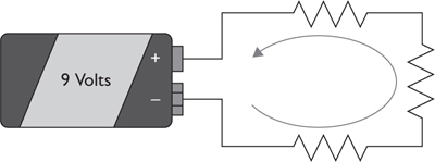
Figure 10-3 Current through a series circuit
In a parallel circuit (Figure 10-4), the voltage remains the same across the loads. Current divides and takes all available paths to return to the source, while the resistance of each path determines how much current flows through each path.

Figure 10-4 Current through a parallel circuit
Although the majority of the current in a parallel circuit will flow through the path of least resistance, remember that current will take any and all available pathways, even if it’s an unintentional path. The voltage will be constant in all parts of the circuit.
Capacitors
A capacitor is a circuit component that stores electrical energy. It is sort of like a battery, except it can’t produce new electrons. Instead, it stores energy created by a battery or other source. Capacitors consist of two metal plates that are separated by a nonconducting substance, called a dielectric. When the plates are connected to a charging device, such as a battery, electrons are transferred from one plate to the other. The greater the voltage—and the larger or closer the plates are—the greater the charge that can be stored.
A charged capacitor discharges when a conducting path is present between the plates. For a given capacitance value, expressed in farads, a capacitor will have a greater opposition to AC current flow at lower frequencies than at higher frequencies. This property is known as capacitive reactance.
If you’re reading electrical diagrams, the capacitor is what’s shown in Figure 10-5.

Figure 10-5 A capacitor symbol
In electronic circuits, capacitors serve four primary purposes.
• Capacitors store charge for high-speed use, especially with lasers.
• Capacitors eliminate ripples in DC voltage. Capacitors can even out uneven voltage by absorbing peaks and filling in valleys.
• Capacitors can block DC current from flowing between two circuit elements while allowing AC current to pass.
• Capacitors are used to form “tuned” circuits, which are used in radios and speaker crossovers, to name a few applications.
Figure 10-6 shows a capacitor in series with a load, shown as a resistor. The capacitor impacts the flow of current through this circuit.
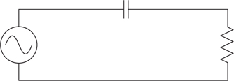
Figure 10-6 A capacitor (top) in a series circuit
As frequency increases in this circuit, so does current flow. Capacitors pass high frequencies and block lower frequencies. Because cables themselves act as capacitors, this concept can be applied to signal loss over distance. More cable creates more capacitance, resulting in a greater loss of high frequencies.
NOTE The shield and center conductor in a coaxial cable act as a capacitor. They are separated by a dielectric.
Inductors
An inductor, also known as a coil, has the opposite effect of a capacitor. It opposes any change in current. Inductors pass low frequencies and block higher frequencies. For a given inductance value, expressed in henries (plural of henry), the inductor will have a greater opposition to AC current flow at higher frequencies than at lower frequencies. Inductance is the property of a circuit that opposes any change in current.
Figure 10-7 shows an inductor, or coil, in a series circuit. The load is shown as a resistor. As the frequency of the circuit increases, the current flow decreases.

Figure 10-7 An inductor (top), or coil, in a series circuit
Coils and Magnetic Induction
Coils carrying current create magnetic fields. These magnetic fields can spread across other components in a circuit and induce current flow. This is how a transformer works; it creates a field that gets picked up by a secondary coil.
A transformer is a passive electromagnetic device usually consisting of at least two coils of wire (inductors) with no electrical connection between them. Often, these coils share an iron-based core. This common core helps concentrate the magnetic force created by current flow in one coil (primary), thereby inducing a voltage in the other coil (secondary). Coils are used in every transformer.
Sometimes the induced voltage is unintended, which creates noise. Figure 10-8 shows magnetic fields crossing from one conductor to another. We will discuss transformers in more depth later in this chapter.

Figure 10-8 Conductors create magnetic fields.
Coils, Capacitors, and Resistors in a Series Circuit
In a series circuit, AC current can flow only where the frequency coil and capacitor cross over. Figure 10-9 shows a series circuit in which the capacitor blocks lower-frequency current, while the coil blocks higher-frequency current.

Figure 10-9 A series circuit with a capacitor and a coil
In Figure 10-10, the circuit’s current is represented along the y-axis and its frequency along the x-axis. The darker curve represents the coil current flow; the lighter curve is the capacitor current flow. The shaded area beneath is the total circuit current flow.

Figure 10-10 Where coil current flow and capacitor current flow intersect, you have a crossover.
The intersection of the two curves creates an x, which is known as the crossover or x-over. This is where the effects of the capacitor and coil cross. Current can flow in this circuit only in this frequency region. The result is that only a portion of the frequency range can pass current. This is a band-pass filter.
Coils, Capacitors, and Resistors in a Parallel Circuit
In a parallel circuit, AC current flows except at the frequency crossover point. In the parallel circuit shown in Figure 10-11, the capacitor passes higher-frequency current, while the coil passes lower-frequency current.

Figure 10-11 A parallel circuit with a coil and capacitor
In Figure 10-12, the circuit’s current is represented along the y-axis and its frequency along the x-axis. The darker curve represents the coil current flow; the lighter curve is the capacitor current flow. The shaded area is the total circuit current flow. The dip at the crossover represents a reduction in current flow. This is a notch filter. You can find these types of circuits in audio equalizers.

Figure 10-12 A notch filter, where the current flows intersect, marks a reduction in total circuit current flow.
Specifying Electrical Power
When a building is built or a room remodeled, an electrical engineer plans for supplying electricity throughout the space. These general plans don’t usually include requirements for AV systems, in part because each AV system is different—from a single projector and screen to a fully integrated and custom videoconferencing suite.
AV designers need to do everything from specify receptacles and power locations to calculate expected current loads for each piece of AV equipment. You may also find you have some specialized electrical power and grounding requirements based upon the size and signal-to-noise requirements of an AV system.
In addition to specifying power locations and requirements, AV designers do the following:
• Specify or design interface and connection plates
• Specify junction-box sizes and locations
• Perform conduit-fill calculations
• Size conduit and cable trays
• Create conduit riser diagrams
• Review electrical plans and schedules to confirm they meet AV requirements
To do all this properly, an AV designer must know local codes and regulations so that the infrastructure is safe, conforms to standards and best practices, and can be understood by electrical engineers and contractors.
Established Terms
You may come across slang terms while working with power and grounding. The IEEE Standard 1100-2005, Recommended Practice for Powering and Grounding Electronic Equipment, identifies a list of terms to be avoided because they’re just not clear. Still, several of them are commonly used in the AV industry, such as the following:
• Clean ground
• Clean power
• Computer-grade ground
• Dedicated ground
• Dirty ground
• Dirty power
• Equipment grounding safety conductor
• Frame ground
• Shared circuits
• Shared ground
Don’t use these terms! Electricians or other project team members might misinterpret your meaning. For example, what exactly is clean power? Because this term does not have a clear definition, your idea of clean power may be different from your co-worker’s or the electrician’s. Because AV integration relies so heavily on an electrician’s work, avoid ambiguous terms to ensure your message gets across. And learn the electrician’s power and grounding vocabulary to ensure your safety as well. Use electrician terms, such as the following:
• Panelboard
• Individual branch circuit
• Supplemental ground
• Isolated ground
These terms have clear definitions; electricians will know exactly what you mean when you use them. When in doubt on terminology, check your country’s regional authority. Most countries have standardized methods and procedures, which they will publish as code for all electricians to follow. Two examples of such codes include the National Electrical Code (NEC), which is used in the United States and some other countries, and BS 7671: IET Wiring Regulations, which is used in the United Kingdom. Always check with the AHJ for the code in your area.
Codes and Regulations
AV professionals must use and reference standards and codes in their AV designs. Each local jurisdiction will normally have a code that consolidates all general and permanent legislation, organized into a code of ordinances. Building codes will be included in the municipal code, and a local jurisdiction may adopt a county’s or state’s building code.
Whether you’re working at the local, regional, or national level, building and electrical codes will probably be adopted from one of the major code publishers. There are two major code publishers in the United States: the International Code Council (ICC), which publishes the International Building Code (IBC), the International Green Construction Code (IgCC), and others; and the National Fire Protection Agency (NFPA), which publishes the NEC and others.
It’s important that you understand the relevant codes because you need to verify that your electrical infrastructure specifications and AV systems installation are compliant. You may work on a project that crosses jurisdictions, and their codes may conflict. In such cases, it is always best practice to follow the more restrictive or stringent code requirements. When in doubt, consult with the AHJ.
Electrical Distribution Systems
In all but the simplest systems, current draw, voltage, and the locations and types of receptacles required for AV equipment must be calculated, specified, and located on drawings. For a new facility or major renovation, this information will go to the electrical engineer and contractor for inclusion in their drawings and specifications. For AV integration in an existing facility, the required electrical circuits and receptacles may be coordinated through the owner, a building engineer, or an electrical contractor. In some cases, an AV firm may have a contracted electrician who can evaluate the situation and add the necessary circuits and receptacles.
In any case, you should perform simple tests on the electrical receptacles in a space to check for proper voltage and grounding prior to connecting AV equipment. In addition, you should locate overcurrent-protective devices, such as circuit breakers, for AV circuits. In larger installations, you may have to inspect the electrical system further to ensure that it meets your specifications.
Electrical contractors need to know how much power your AV system requires so they can plan accordingly. To communicate effectively, you need an intermediate understanding of power distribution.
So, where does the power for your AV system come from? At a power-generation station, the generator puts out extremely high-voltage AC, which travels to a transmission transformer for the long trip down the power lines. Because transmission at high voltage reduces the amount of current, there is less loss from resistance. This means long-distance transmission can serve a broad geographic area.
These primary transmission lines deliver power to electrical substations, which are located strategically around population areas or industrial centers. The substations have transformers that reduce the voltage before local distribution. The electricity is then distributed to a local transformer, where it is further reduced to the voltage required for your application—whether residential or commercial.
When the power from the substation’s transformer reaches your local transformer, it normally has to be reduced to the voltage required for your AV systems. This reduced power can be distributed to your AV systems in two ways: single-phase or three-phase, which we will discuss next. In a single-phase system, voltage and current flow change in response to each other. In a three-phase system, there are three alternating currents that vary in phase. It’s important to know which type of power you need so you can communicate with the electrician and ensure the right amount of power to get your equipment running efficiently and effectively.
Power Distribution Systems
AC power distribution systems are also referred to by the number of wires carrying the power. The most common single-phase system in North America is 120/240 V (Figure 10-13). The 120/240 V single-phase system uses three wires. Two-line wires carry voltage; a third is neutral. Voltage between a line conductor and neutral will be 120 V, while voltage between the two line wires will be 240 V.

Figure 10-13 Single-phase power distribution system
The single-phase power distribution system is used in almost all homes in North America and Europe, where the needed load is relatively small. It can also be used in small commercial buildings with lesser power demands. An additional equipment grounding conductor (EGC) is added for safety.
In commercial buildings, you’ll find that power almost always comes into the building as three-phase. The most common three-phase systems in North America are 120/208 V and 277/480 V.
The 120/208 V three-phase system uses four wires, as shown in Figure 10-14. Three-phase wires carry electricity, while the fourth is the grounded conductor (or neutral). Voltage between a phase wire and ground will be 120 V. Voltage between any of the three phase wires will be 208 V. An equipment grounding conductor is added for portable power distribution systems. Because of its flexible nature, this is the most popular system used in commercial, institutional, and light industrial buildings.

Figure 10-14 A 120/208 V three-phase system
The 277/480 V three-phase system (Figure 10-15) is similar to the 120/208 V system. You could even say the 120/208 V system evolves from this system for AV and other receptacles.

Figure 10-15 A 277/480 V three-phase system
The 277/480 V system is used in large commercial and industrial buildings. It also employs four wires and is important to be aware of because it is primarily used for room lighting, not for AV equipment. When AV systems incorporate lighting controls, you have to factor in lighting systems that use a 277 V power system.
In a perfect world, when working with three-phase systems, you want all the power for AV equipment to come from only one of the phases. Interconnected equipment powered by different electrical phases can interact with each other, causing noise.

TIP With any three-phase electrical distribution system, the electrical engineer will attempt to design a balanced load on the different phases. Keep in mind that a large, infrequently used AV system would not be placed on one phase of the building’s power system. If it is, the system will be unbalanced, either when running or when idle. This can cause damage to the electrical system.
International Power Distribution Systems
Although North America, Japan, and parts of South America use 60 Hz systems, most of the rest of the world uses 50 Hz electrical-distribution systems. These systems are similar but operate at about double the voltage. The most common 50 Hz electrical-distribution systems are 230 V single-phase and 230/400 V three-phase.
A 230 V single-phase system (Figure 10-16) is similar to a 120 V single-phase system used in North America. The main difference is that the higher voltage reduces the amount of current required. This system uses three wires. The first wire carries 230 V of AC power, the second wire is the system ground, and the third wire is the EGC. This system is typically used for residential and business purposes.

Figure 10-16 A 230 V single-phase system
A 230/400 V three-phase system (Figure 10-17) is similar to a 120/208 V three-phase system used in North America. This system uses five wires. The first three wires carry 230 V between the individual phases and neutral and carry 400 V between phases, the fourth wire is the neutral, and the fifth wire is the EGC. This system is commonly found in commercial and industrial applications that have greater power requirements, such as larger buildings, small manufacturing, and AV staging events.

Figure 10-17 A 230/400 V three-phase system
Understanding Power Onsite
Electrical service refers to the conductors and equipment necessary for delivering energy from the electricity supply system to the wiring system of the site that it’s meant to serve. Figure 10-18 shows the flow of electrical service onsite.
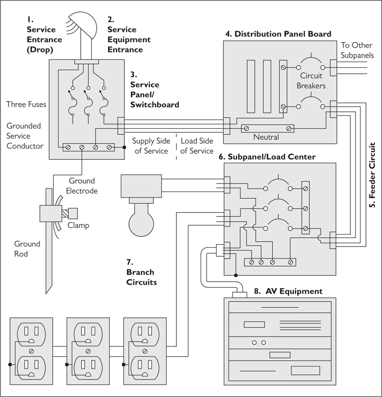
Figure 10-18 Onsite electrical service
1. Service drop refers to the overhead service conductors from the last pole, other aerial support, and underground feeds outside the building, connecting to the service-entrance conductors at the building or other structure.
2. The service entrance is the point at which power enters the building.
3. The service panel, or switchboard, receives the incoming power and adds a ground conductor.
4. The distribution panel board distributes the power to subpanels throughout a facility.
5. The feeders are circuits that carry power between the service panel and the distribution panel.
6. Subpanels have current-limiting devices, such as circuit breakers or fuses. An individual circuit might provide power to all the lights in the room, or several electrical convenience outlets, but the total power consumed on the circuit cannot exceed the current-limiting device’s rating or else the circuit breaker trips or a fuse blows.
7. From the panel, the branch circuits run power to wall outlets or directly to wired equipment. This powers the various amplifiers and signal-processing racks, communications equipment, and AV equipment.
The Master Technical Power Panel
A larger facility usually derives all its power from one central location: the master technical power panel. Ideally, one phase of power should be designated as the technical power supply and be fed directly by its own primary feeder and transformer, winding up at the primary power distribution center for the building.
The master technical power panel will distribute power (and the technical ground) to all other locations within a facility. Its location varies. Here are some examples:
• In a one-room studio, it may be the service-entrance panel for the entire building; there will be no feeders or subpanels, only branch circuits.
• In a small theater or studio facility, the master technical power panel is often located in or near the control room and provides all the branch circuits for local and remote locations.
• In a large complex, the master technical power panel may be in an equipment or utility room and will power feeders that, in turn, power subpanels and branch circuits. There could be several levels of subpanels in large complexes.
Specifying AV Circuits
AV designers may be responsible for calculating the number of circuits needed to support their AV systems. Projectors, screens, displays, conference room tables, lecterns, credenzas, and more may all require power.
For starters, review your project documentation for the location of all equipment, plus other locations that require power, such as a conference table. Match the equipment to receptacle locations. Receptacles can be single, duplex, or quad, and they can be located in ceilings, walls, and floorboxes.
In circuits that carry power to AV equipment, the complete path begins with a line—or “hot” conductor—connected to one side of the local AC power transformer (the power source). The path continues through the electronic equipment, returning via the neutral conductor and back to the other terminal on the AC power transformer, ultimately returning to the power source. See Figure 10-19.

Figure 10-19 Circuits that power AV equipment
TIP In North America, the line conductor is a black, insulated wire, and the neutral is the white, insulated wire.
Branch Circuit Loads
For safety reasons, a branch circuit (Figure 10-20) can handle only a certain amount of current. In a commercial environment, a typical branch circuit is rated for 20A. If more current is drawn through the circuit, it will trip the breaker, cutting all power to the branch circuit.

Figure 10-20 Branch circuits
Most electronics that you plug into an outlet—a coffee pot, computer, or copier—require less than 20A. However, designers must calculate the total amperage needed when the branch circuit is in typical use. In other words, can the circuit handle the coffee pot, computer, and copier running at the same time?
To do this, you need to know which outlets and directly wired equipment are connected to a given branch circuit. Each piece of equipment has a power-consumption rating. One may specify “120V 1.6A,” while another is rated “115V 4.2A.” When you add together the amperage of those devices in one system, you know the maximum current needed would be about 1.6A + 4.2A = 5.8A, which easily works for a single 20A circuit. If the needed current exceeded 20A, the circuit breaker would trip, shutting off the flow. You should plan for a decent buffer between the needed amperage and the circuit’s rating. In the U.S., this buffer is defined by the NEC as 80 percent of capacity.
TIP Per NEC code, don’t plan to use more than 80 percent of the available current in a branch circuit (in other words, 16A on a 20A circuit).
Calculating the Number of Circuits
Say you are designing a classroom for a university. The architect and electrical engineer have provided a floor plan (Figure 10-21). At this point in your design, you’ve already placed equipment in the room—two flat-panel monitors and two projectors for a visual system. You’ve got an AV rack in the back of the room and a document camera at the lectern in front.

Figure 10-21 AV in a university classroom design
All the AV gear requires power, so you need to ask the electrical engineer to place receptacles at these locations. Based on this drawing, you request four duplex receptacles, one by each projector and monitor, and two junction boxes, by the rack and at the lectern. Each piece of AV gear draws a certain amount of amperage. The rack requires 12A, the monitors and document cameras require 3A, and the projectors require 5A. See Figure 10-22.

Figure 10-22 Receptacle locations in an AV installation
You have looked up circuit information from your AHJ and determined that you will use 20A circuits, but you can use only 80 percent of that, or up to 16A of continuous load per circuit. When you add up the amperage for the devices you plan to put on an individual branch circuit, you will need to add a circuit every time you hit 16A.
Figure 10-23 shows one solution for this room. The receptacles have been divided into three groups. Circuit 1 has the rack at 12A, circuit 2 has two projectors at 10A, and circuit 3 has two monitors and a junction box at 9A.

Figure 10-23 Sample circuit arrangement in an AV installation
Once you’ve documented how many circuits your system will require, you will want to include some general notes somewhere on the drawing. The notes may read something like this:
• Circuits for AV use only. Do not share with any non-AV loads.
• All AV circuits must include auxiliary equipment grounding conductor.
• All AV circuits must originate from same phase and use the same panelboard.
At a minimum, the circuits specified for the AV system should be labeled for AV system use only. In other words, no non-AV loads should be shared with the circuits designated for the AV system or computers associated with the AV system.
Also keep in mind that the circuits for an AV system should include an auxiliary equipment grounding conductor (EGC). An electrical specification or installation might not use bare copper wire as the EGC; it may rely on the electrical metallic tubing (EMT) conduit. EMT consists of couplers and set screws. Specifying an auxiliary EGC eliminates relying solely on the EMT as the only equipment grounding conductor.
Power Strips and Cords
When you have several devices that require power from a single location, you could use power strips (a.k.a., relocatable power taps). Power strips come with their own set of safety standards, such as a UL or CE mark, meaning they’re listed by Underwriter Laboratories or Conformité Européenne for specific or limited usage. The UL website says, “Products that bear the UL Classification mark have been evaluated for specific properties, a limited range of hazards, or suitability for use under limited or special conditions.” The CE website says, “The CE marking is the manufacturer’s declaration that the product meets the requirements of the applicable EC directives.”
To keep this section brief, we’ll use UL as a discussion point for power strips. If you are designing within the United States, the National Electrical Code states, “Listed or labeled equipment shall be installed and used in accordance with any instructions included in the listing or labeling.” Compliance with the NEC also requires compliance with how the device is listed.
UL uses the term relocatable power taps (RPTs) for power strips. Here are some excerpts from various UL publications regarding RPTs:
• These requirements cover cord-connected, relocatable power taps rated 250V AC or less and 20A AC or less.
• A relocatable power tap is intended only for indoor use as a temporary extension of a grounding alternating-current branch circuit for general use.
• A cord-connected relocatable power tap is not intended to be connected to another cord-connected relocatable power tap.
• Relocatable power taps are intended to be directly connected to a permanently installed branch circuit receptacle.
• Relocatable power taps are not intended to be connected (daisy chained) to other relocatable power taps or to extension cords.
• Relocatable power taps are not intended for use at construction sites and similar locations.
• Relocatable power taps are not intended to be permanently secured to building structures, tables, work benches, or similar structures, and they are not intended to be used as a substitute for fixed wiring.
NOTE You should not daisy-chain power strips, as shown in the following illustration. Power strips should be plugged directly into a branch circuit receptacle, not at the end of an extension cord. Because rack-mounted power distribution units (PDUs) fall under a different UL classification, you can plug a power strip into a PDU, but you cannot plug a power strip into another power strip. A PDU is a rack-mountable or portable electrical enclosure, connected via cord or cable to a branch circuit for distributing power to multiple electronic devices. It may contain switches, overcurrent protection, control connections, and receptacles.

And then there are power cords—a key element of getting power to an electronic device. In AV, power cord management is important. Sometimes power cords are too long, and they must be wrapped and secured neatly. Let Figure 10-24 be your guide to best practices.

Figure 10-24 Best practices in power cord management
You should consider neatness and accessibility when placing a cord within a rack or equipment area. The first illustration on the left shows a power cord wrapped as a coil. This is an acceptable way to tie a power cord. Folded cords, as shown in the second illustration, are also acceptable. Historically, the practice of coiling a power cable has been a topic of some debate. There are those who contend that coiling a power cord creates a large inductive loop. But there are manufacturers in the industry that have performed extensive testing and found no evidence of this effect.
The illustration on the far right is unacceptable because it would be hard to access the individual cords for service. Removing the cord for one piece of equipment would mean unbundling several cords. It also has the potential for heat buildup in the power cables. In high-current draw situations, the cords feeding the devices can become warm to the touch. Several cords wrapped tightly together can potentially create smoke or cause a fire.
For serviceability purposes, power cords that are removable from equipment can be secured with nylon ties (zip ties), whereas power cords that are permanently attached to equipment should be secured with Velcro (a.k.a., hook and loop fastener).
TIP Longer power cords often take up more space in a rack and require extra attention. For equipment with detachable power cords, neater cable management can be achieved by replacing longer cords with shorter cords.
Grounding (Earthing)
In the context of electrical power, ground refers to an earth connection or something that extends an earth connection. If an electrical device is “grounded,” it means the device is connected either to earth or to some conductive body that extends to the earth. The earth is used as the 0 volt reference for AC power distribution. This grounding (earthing) provides a reference point of no potential—the earth in this case—for an electrical circuit.
NOTE In North America, the terms ground, grounded, and grounding are used. Outside of North America, the terms earth, earthed, and earthing are used. Regardless of which terms you favor, in the context of electrical power, they all refer to the same concepts.
Grounding is an important safeguard. Connecting one of a system’s current-carrying conductors to earth limits the amount of voltage that can be imposed on the line. Lightning, line surges, and unintentional contact with higher voltage lines can increase the potential of the circuit, leading to a possibly fatal situation. System grounding helps reduce fires in buildings, as well as voltage stress on electrical insulation. This provides longer insulation life for motors, transformers, and other system components.
System Grounding
To protect your AV system from unexpected sources of high voltage, you need to ensure that your equipment is integrated into a system grounding scheme. System grounding will limit the voltage imposed by lightning, line surges, or unintentional contact with higher-voltage lines. It will also stabilize that voltage to earth during normal operation. System grounding is when one of the current-carrying conductors—usually the neutral—is connected to ground.
To envision what we’re talking about, let’s revisit the basic circuit (Figure 10-25). In this system, the receptacle is connected directly to the power source—a transformer. In reality, however, the receptacle would be connected to a panelboard. A panelboard is a component of an electricity supply system that divides electricity from a power source into individual circuits.

Figure 10-25 A basic circuit, with ground
Figure 10-26 shows our power and grounding system with a panelboard. It also has an overcurrent protection device called a circuit breaker. The circuit breaker will protect users and electrical equipment from damage due to an overload or short circuit by interrupting current flow.

Figure 10-26 A circuit with a panelboard and a circuit breaker
The panelboard also include a neutral bus. A busbar is a strip of conductive material that provides a common connection point. In the case of the neutral busbar, all the neutral wires are terminated on the busbar. Figure 10-26 also shows that the neutral busbar not only is connected to the neutral return but also is connected to ground (earth). This ground connection protects people and equipment from stray electrical currents and electrical faults.
System-Grounding Conductors
You can recognize a system-grounding scheme by its use of a neutral—or grounded—conductor. Current seeks to return to the source, and the neutral conductor is the path that current normally takes.
For safety reasons, the current-carrying neutral is also connected to a grounding electrode through the panelboard at the service entrance of a building (where electrical power comes in). The neutral wire that services the building will also be grounded at the transformer outside. In other words, in system grounding, the normal return path that current takes back to the source is on a neutral conductor attached to the ground: a grounded, neutral conductor.
Equipment Grounding
Not only should the electrical system be grounded, but the housings of electronic equipment should also be grounded. Electronic equipment with metal cases or exposed screws may become energized if they accidentally come in contact with a line conductor (an electrical fault). Equipment grounding will prevent the exposure to voltage that these cases might carry in such scenarios by opening a fuse or breaker.
The following equipment should always be grounded:
• Electrical equipment enclosures
• Panelboards, switchboards
• Junction boxes, backboxes
• Receptacles, audiovisual plates, and so on
• Raceways
• Conduit, cable trays, and so on
• Any other metallic or conductive housing that has the potential to become energized in a fault situation
• Metal housings enclosing a receptacle or power outlet, as well as panelboard enclosures
Figure 10-27 shows an example of equipment grounding. The electronic device could be a projector or other AV system.

Figure 10-27 Grounding for a piece of AV equipment (the electronic device)
The dotted line shows a continuous pathway to ground beginning with the metal enclosure of the electronic device, through the third prong of the electrical plug, through the electrical receptacle (socket), back to the panelboard, through the main bonding jumper, and to the neutral bus, which is connected to earth.
Equipment-Grounding Conductors
Equipment grounding is when you use a grounding conductor separate from the neutral conductor. Generally, this wire is green or green-yellow.
There are many ways to ground equipment, including bare copper or insulated wires. Equipment grounding is accomplished through an equipment grounding conductor that runs with or encloses the circuit conductors. A bare copper wire may serve as the equipment-grounding conductor, but other types may be allowable, including the following:
• Any shape of copper, aluminum, or copper-clad aluminum conductors that may be solid, stranded, insulated, covered, or bare.
• A busbar of any shape.
• Rigid metal conduit.
• Intermediate metal conduit.
• Electrical metallic tubing (EMT).
• “Listed” flexible metal conduit that meets certain code conditions. Listed means listed by a Nationally Recognized Testing Laboratory (NRTL) such as Underwriters Laboratory (UL).
• Cable trays as permitted.
• Surface metal raceways listed for grounding.
NOTE Some regions may not allow EMT or conduit to serve as an equipment grounding conductor, so check your local codes and regulations.
The grounding path must not be only continuous but also reliable and of low impedance. In the case of an accidental connection between a line conductor and a grounded metallic device, this pathway must be in place to allow the current to return to the source via the equipment grounding conductor. This path must also be of low enough impedance to allow the high current required to activate the circuit’s overcurrent protection device.
Ground Faults
The purpose of an EGC is to protect people. Say an integrator has installed an AV device, but the power supply becomes defective. The insulation may have melted away or some internal component came loose or failed. The result is an accidental connection, called a ground fault, between the line conductor and the metal enclosure of the device. This ground fault brings the metal enclosure of your AV device up to mains voltage.
The human body has about 1,000 ohms of resistance, depending upon where you measure the conductivity of your skin. If a human came into contact with a ground fault or energized equipment, as much as 120mA could flow through the human body—enough to cause muscle contraction, heart failure, nerve damage, or death.
In an ideal grounding system, current will flow along the line and neutral conductors. In our hypothetical situation, because of some damage or defect in the equipment, the line conductor of the electrical circuit has come into contact with the metal enclosure of the electronic device, such as a projector. The current flows from the ground fault to the EGC.
Now, when current flows from the transformer, to the panelboard, to the receptacle, and to the electronic device, the device’s enclosure will carry line voltage. In other words, the electronic device’s metallic enclosure will be energized to 120 or 230 V of electricity. Fortunately, the metal case is bonded to the EGC via the third prong of the device’s power cord, which is plugged into a three-prong AC receptacle. Therefore, current is carried away from the device.
From there, the three-prong receptacle has an equipment-grounding screw used to attach the EGC. The EGC is run with the line and neutral conductors back to the panelboard. At the panelboard, the EGC is connected to the equipment-grounding bus, which is bonded to the neutral bus in the panelboard.
Once at the neutral bus, the current starts its return to the source. If the current draw is high enough through the low-impedance fault path, the overcurrent device (circuit breaker) will trip. This breaks the circuit, and the voltage is removed. See Figure 10-28.

Figure 10-28 A device defect will trip the circuit breaker in a properly grounded system.
NOTE The National Electrical Code requires that there be an “effective ground-fault current path,” defined as “an intentionally constructed, permanent, low-impedance, electrically conductive path designed and intended to carry current under ground-fault conditions from the point of a ground fault on a wiring system to the electrical supply source and that facilitates the operation of the overcurrent protection device….” This permanent joining of metallic parts to form an electrically conductive path under ground-fault conditions is known as bonding.
The Dangers of Three-to-Two-Prong Adapters
Some AV professionals troubleshoot ground faults using a three-to-two-prong AC adapter. But have you ever considered what a three-to-two-prong adapter does? It removes the ground fault current path, which could bring the enclosure to line level.
Remember that electricity will take any and all available pathways to return to the source. When you use a three-to-two-prong adapter, you interrupt this pathway. If a person were to touch this now energized enclosure, current would flow through the person to ground.
If you have a hum problem, instead of removing the third pin or using a three-to-two-prong adapter, you should follow proper troubleshooting procedures to discover the cause of the problem.
Three-to-two prong adapters should be used only when they are secured to a grounding pin, such as a grounded faceplate screw, as pictured.

Isolated Ground
An isolated-ground system is intended to minimize interference problems, such as hum and buzz, caused by problematic ground loops. It also provides a more stable reference for the audiovisual circuits and can possibly reduce the noise level getting into the audiovisual system.
In an isolated-ground system (Figure 10-29), the equipment ground for the AV system power is isolated from the regular equipment ground. AV equipment racks and other AV enclosures also need to be isolated and insulated from contact with grounded objects, such as conduit, building steel, and conductive concrete floors.

Figure 10-29 An isolated grounding scheme, indicated by the dotted wire
Isolated ground conductors are only isolated from the normal equipment ground up to the point where the system and equipment ground conductors come together in the main panelboard. The system, equipment, and isolated ground systems all need to be bonded together at the main panelboard. This ensures that any fault current has a low-impedance pathway back to the source.
Some AV systems require a technical power system. A technical power system is a power system designed especially for AV systems and associated computers and utilizes an isolated ground. Such systems are useful in critical-listening environments that require a low noise floor, such as broadcast studios, postproduction facilities, performing arts centers, recording studios, and other critical listening environments.
Residual noise from interference, problematic ground loops, and more will be evident in environments with low noise floors. Assuming good design practices and properly adjusted gain structure, the normal acoustic noise floor in noncritical listening spaces will mask any system noise.
Isolated Ground Receptacles
Isolated ground systems have their own unique receptacles. Normally, as in Figure 10-30, the equipment ground pin, the flanges, the cover screw in the center of the receptacle, and the equipment grounding screw all have continuity among them. In other words, they’re all connected electrically.

Figure 10-30 Normal receptacle
Figure 10-31 shows an isolated ground outlet. An isolated receptacle is a receptacle in which the grounding terminal is purposely insulated from the receptacle mounting. The color of such receptacles may vary, but the important identifier is the triangle symbol at the lower right of the receptacle. In an isolated ground receptacle, the equipment ground pin and the equipment grounding screw are insulated from the flanges and the cover screw.

Figure 10-31 Isolated ground receptacle
Usually, in an isolated-grounding scheme, an insulated green wire with a yellow stripe is used as the EGC (check your local code). That isolation continues only until the bonding point at the service entrance where the neutral, equipment grounding conductor, and isolated-grounding conductor are bonded together. In Figure 10-31, there is a second green wire to the far left. This is the electrical system’s normal EGC. This wire is for fault protection within the outlet’s box and cover plate.
Interference Prevention and Noise Defense
Now that you’ve learned about circuit theory and power and grounding, you’ll study ways to prevent interference in your AV systems. This section will help you understand basic field theory behind the causes of interference and offer strategies for combating noise.
Interference, or noise, is any electrical signal in a circuit that’s not the desired electrical signal. The most common evidence of interference is a hum or buzz.
Hum is defined as an undesirable 50 or 60 Hz noise emanating from an audio system. It can manifest in a video system as a rolling “hum bar” on the display. Buzz is a hum with additional harmonic energy.
How does interference find its way into an audio or video signal? First, there has to be a source of interference and a device that’s sensitive to the interference. You may hear the two referred to as source and receiver, source and victim, or source and receptor.
Second, there must also be a means or pathway by which the interference goes from source to receiver. This is what’s known as field theory, or the transfer of energy from one circuit to another via an electrical or magnetic field. There is no physical contact between circuits during this energy transfer. It usually occurs either by magnetic-field coupling or by electric-field coupling.
Magnetic-Field Coupling
As current flows through a conductor, a magnetic field develops around that conductor. This magnetic field is often depicted as invisible lines of force (recall Figure 10-8), also referred to as magnetic lines of flux. As the current level remains constant, the lines of flux remain stationary. This explains what happens with DC, because the current is flowing in only one direction, so the field doesn’t change over time.
In the case of AC, the magnetic field expands, contracts, and changes direction in response to changes in the intensity and direction of the current. With increased current flow in the conductor, the density of these magnetic lines of flux increases in direct proportion to the current flow; the lines of flux weaken as they get further from the conductor.
Current (the flow of electrons) can be made to move through a conductor when there is relative motion between conductor and magnetic field. This means that current can be made to flow either by moving a conductor through a magnetic field (thereby cutting across the magnetic lines of flux) or by making the magnetic field (the lines of flux) expand and contract around a stationary conductor.
For example, a conductor carries AC current at 60 cycles per second (60 Hz). As the current changes in intensity and direction, the surrounding magnetic field expands, contracts, and changes direction in relation to the current flow in the conductor. Now consider a second conductor placed within the changing magnetic field of the first conductor. As the magnetic field from the first conductor expands, contracts, and changes direction, the lines of flux cut across the second conductor, thereby pulling and pushing at the electrons in the second conductor.
This pulling and pushing force is voltage. Although this is a desirable effect in a transformer, it is not desirable in most other situations. In other words, the expanding, contracting, and direction-changing signal on the AC conductor—at 60 cycles per second—is transferred to the second conductor. This is called magnetic-field coupling.
Electric-Field Coupling
The attraction of unlike charges just described is called an electric field. Electric fields weaken as atoms move farther apart.
Positively or negatively charged bodies (containing either positively or negatively charged atoms) exert influence on the space surrounding them. For example, a positively charged conductor (lacking electrons) creates an electric field in the surrounding region, attracting electrons. This attraction—the electric field—creates a negative charge in a nearby conductor through what is called electric-field coupling. This difference in charge creates a voltage potential between the two conductors. The movement of electrons that creates this voltage potential is current flow. As long as there is no physical connection between the two conductors, the voltage potential will remain.
When two conductors are separated by an insulator (dielectric), along with a difference in potential between them (voltage), there’s an electric field between the two conductors. The strength of the electric field increases in relation to the difference in voltage that exists between the two conductors.
With DC, the field doesn’t change over time—it’s static. Current is flowing in only one direction; therefore, the electric field extends out, and the lines of force are stationary. With AC, the polarity of the field changes over time, because the electric field expands and contracts. Therefore, the polarity of the electric field changes with the changes in voltage.
The capacity (ability to store a charge) of the electric field depends on the distance between the conductors, the surface area of the conductors, and the dielectric strength of the insulating material between the conductors. Dielectric strength refers to the maximum safe voltage of the insulating material between the conductors before the dielectric breaks down and an arc occurs, equalizing the charge between the two bodies or conductors. For example, air is the dielectric (and a good insulator) between charged storm clouds and the earth. A lightning strike is a breakdown of the dielectric—the air in this case—equalizing the charge between cloud and earth.
Although electronic components specifically designed to have high capacitance are known as capacitors, an electric field will exist between any two conductors with a difference in potential (voltage) between them. And as insulators are not perfect, some current will flow through the insulator (dielectric) between conductors.
NOTE Dielectric strength is the maximum safe voltage of the insulating material between two conductors before the dielectric breaks down and an arc occurs, equalizing the charge between the two bodies or conductors.
Shielding
A shield is a metallic partition between two areas. It’s used to control the propagation of electric and magnetic fields from one area to the other. Shields are used to contain electric and magnetic fields at the source or to protect a receiver from electric and magnetic fields. A shield can be the metallic chassis that houses an electronic device or the enclosure (aluminum foil or copper braid) that surrounds a wire or cable.
Shielding works bidirectionally. It prevents signals from getting out or getting in, stopping what are known as egress and ingress. The effectiveness of a shield is determined by the type of field, the material used for shielding, and the distance from the source of the interference.
AV pros can implement shielding in a variety of ways. They can provide coverage around a single insulated conductor or around individual insulated conductors in a multiconductor cable. You can also specify shields that surround multiple insulated conductors. Shields can even provide a return path for current that originates at sources of interference.
There are three basic types of cable shielding: foil, braid, and a combination of the two.
• Aluminum foil shielding This employs a thin sheet of aluminum wrapped around an insulated conductor or conductors.
• Copper-braided shielding This employs many tiny, interweaved wires around an insulated conductor or conductors.
• Combination shields These employ both foil and braid types of shielding.
As alluded to earlier, the main criteria for specifying a shield are coverage, flexibility, and frequency range. Coverage is expressed in a percentage, and it indicates how much of the inner cable will be covered. Flexibility is a subjective measurement and correlates with a cable’s flex life. And because shielding cannot protect a conductor from all sources of electromagnetic (EM) and radio frequency (RF) interference, its effectiveness is narrowed to a certain frequency range.
Shielding from Magnetic Fields
Magnetic shielding employs any magnetically permeable material to absorb and conduct magnetic lines of flux to redirect them away from an unintended victim, such as a circuit. Magnetically permeable materials include iron, nickel alloys, and steel, which vary in their ability to conduct magnetic fields. A design that puts AV cabling in steel conduit yields excellent magnetic shielding.
Non-magnetically-permeable materials include aluminum, brass, and copper, which do not have the ability to absorb or redirect a magnetic field. This means that AV cabling with aluminum-foil shielding or braided-copper shields will not guard against interference from magnetic fields at power line frequencies of 50 or 60 Hz.
NOTE Permeability is a material’s ability to concentrate magnetic lines of flux. A magnetically permeable material will concentrate the magnetic lines of flux within itself, rather than let the magnetic lines of flux pass through it.
Shielding from Electric Fields
The purpose of electric-field shielding is to lead current to the equipment-grounding conductor and back to the source. Electric-field shielding employs electrically conductive materials to absorb and conduct electrical lines of the force and redirect them away from an unintended victim.
Foil or braided shielding does an excellent job of absorbing energy from a nearby electric field, but that energy will need somewhere to go. As discussed earlier, electricity seeks to return to the source. A pathway back to the source is provided when the shield is connected to the equipment chassis and the chassis is connected to the third prong of the power cord—the EGC. This pathway back to the source must be a low-impedance connection; otherwise, the current may take a different pathway and create interference somewhere else.
In an ideal scenario, all AV equipment would be connected to a single AC receptacle so that all shields for the interconnecting cables would be ground-referenced to that single receptacle. Often, however, this will not be the case. You may have multiple devices plugged into different receptacles, originating from different circuits, and possibly (though unfortunately) leading to different panelboards. Although all AC circuits may be referenced to the earth connection at the main service entrance, the EGCs may take different pathways. Those different pathways—even when well designed and implemented—may have slightly different impedances, which can create different potentials. When you have different potentials, current flows on the shields of the interconnecting cables.
Ground Loops
A ground loop is any electrically conductive continuous loop. In AV, ground loops are common but not always problematic. For example, consider two AV devices mounted together in an equipment rack and plugged into the same power strip. When the two devices are connected by a shielded cable, it creates an electrically conductive loop through the cable shield, device chassis, and third prongs (EGCs) of the power cords. Although the loop is electrically conductive, the loop area is small and of low impedance. Moreover, both devices’ EGCs reference a common point in the power strip. Therefore, because the loop is of low impedance with a common reference point, there is little—if any—potential difference, and no current flows through the loop.
That said, a ground loop can manifest itself as a hum or buzz in an audio system. AV designers do not need to—nor can they—avoid all ground loops in an AV design. Instead, the design goal should be to identify areas where ground loops could be a problem and then plan accordingly.
The clearest example comes into play when designing an AV solution that spans two rooms. If the rooms use two different panelboards with different amounts of resistance between circuits, you should be able to identify potential ground-loop problems. Difference in potentials allows current to flow on the EGCs and shields of interconnecting cables. Some possible solutions might be to specify an isolation transformer or design a Cat5 or fiber-based solution.
Balanced Circuits
Signal-processing circuitry and cables are continuously exposed to noise and interference. In fact, all electrical circuits and the cabling used to connect them generate energy fields, which can interact with AV circuitry and cabling. Such interference and noise degrades the quality of an audio signal, for example. Noise introduced to a digital signal can even corrupt the data.
One way to reduce the noise in a circuit or cable is to use a balanced electrical design. The terms balanced and unbalanced refer to the impedance balance on two conductors and the circuitry connecting those two conductors.
A balanced circuit is a two-conductor circuit (not including a shield) in which both conductors and all the circuits connected to them have the same impedance with respect to ground. In other words, because the impedances are the same with respect to one another, they are balanced.
A balanced input uses a differential amplifier that responds only to the signal difference between conductors and rejects signals that appear identically—or in common—on both conductors. To help ensure that any unwanted signal or noise is induced onto both conductors as equally as possible, the two conductors are twisted around one another so that both conductors are equally exposed to the offending noise source. If the offending noise is coupled or shared equally on both conductors, it can be rejected by the differential, balanced input. We will discuss differential- and common-mode signals in more detail in the next section.
The design of balanced circuits offers a defense mechanism against noise. In Figure 10-32, the bumps on the sine waves on the output represent noise. These are called common-mode signals because they appear identically on both conductors. When they are combined via the differential amplifier, the input side responds only to the original differential-mode signals, which are out of phase on the two conductors. This defense mechanism removes the noise—or most of it—leaving only the intended signal. As a rule, you should use balanced components whenever you can. The cabling used with balanced circuitry requires two signal conductors. In audio, the two signal conductors are surrounded by a shield.

Figure 10-32 A balanced circuit diagram
Differential- and Common-Mode Signals
Typically, in a balanced circuit, the audio signal will be in differential mode and the noise induced in a cable will be in common mode. In differential mode, different signals are carried on two conductors. In common mode, the same signal is carried on two conductors.
Common-Mode Rejection
The rejection of interference that is induced commonly on two conductors is known as common-mode rejection (CMR). The ability of a specific AV device to reject this common-mode noise is described by its common-mode rejection ratio (CMRR). The CMRR is expressed in decibels, with higher numbers indicating better rejection, usually 70 to 120 dB, depending on need.
This can also be expressed mathematically. The formula for common-mode rejection is as follows:
(S1 + N1) – (–S2 + N2) = ST + NT
where:
• S1 is the signal on the first conductor.
• N1 is the noise on the first conductor.
• – indicates the difference (differential).
• S2 is the signal on the second conductor.
• N2 is the noise on the second conductor.
• ST is the total signal.
• NT is the total noise.
The CMRR equation is 20log (differential gain/common-mode gain), and it assumes an absolute value (positive value) for common-mode gain.
Although good CMRR numbers can be achieved in a laboratory, the real world is quite different. This is because the CMRR values of various electric components in a circuit are not exact values. Typical component CMRRs may vary as much as 5 percent from their stated values.
NOTE CMRR specifications should be stated in accordance with IEC standard 60268-3, which uses a 10-ohm impedance imbalance for testing.
Twisted-Pair Cables and Common-Mode Rejection
To help ensure that any unwanted signal (noise) is magnetically induced onto both conductors as equally as possible, the two conductors on a balanced cable can be twisted around one another. This purposefully and equally exposes both conductors to the offending magnetic field.
Twisting also helps to reject signals that interfere along a distance of the cable. Because of the twists, the interference will induce in one polarity for one segment of the cable, and the other polarity in the second section of the cable as a common-mode signal. This helps to reduce the level of noise generated along the length of the cable.
Transformers
One of the best defenses against common-mode noise is to specify transformers. Electronically balanced circuitry may be less expensive, but it is typically not as good at rejecting common-mode noise. An untapped transformer is inherently balanced, which leads to its excellent common-mode rejection.
A transformer (Figure 10-33) is a passive electromagnetic device, usually consisting of at least two coils of wire (inductors) with no electrical connection between them. These coils often share an iron-based core that concentrates the magnetic lines of force in one coil, thereby inducing voltage into the other coil.

Figure 10-33 A transformer
Common-mode noise will arrive on both ends of the primary side (left) of the transformer. Because it’s common-mode noise, there will not be any potential difference between the ends of the primary side of the winding. Therefore, noise current will not flow through the primary side of the transformer and transfer to the secondary side.
In the real world, consider the 48 VDC phantom power supply used to power condenser microphones. Phantom power provides +48 VDC on pins 2 and 3 of an XLR connector and uses the shield as the circuit return. If, for whatever reason, phantom power is active and applied to a dynamic microphone, both ends of the coil in the dynamic microphone are presented with +48 VDC. The positive voltage is in common mode on pins 2 and 3, so no current will flow through the coil in the dynamic microphone.
Unbalanced Interface
If you do not use a balanced interface, you will need to use an unbalanced interface. In an unbalanced circuit design, the equipment outputs an unbalanced signal to a cable connected to an unbalanced input.
As with a balanced circuit, the cable may pick up noise from surrounding sources. However, with an unbalanced circuit design, there are no noise-defense mechanisms except for the shield. So if noise gets onto the signal conductor, there is no way to remove it. Moreover, if noise flows through the shield of an unbalanced circuit, it becomes part of the problem.
Cables used for unbalanced circuitry have two signal conductors. One conductor carries the signal, while the second conductor—usually the cable shield—acts as the return path. The return conductor is a low-impedance connection to the signal ground and possibly also to earth ground. The impedance of the signal circuitry is quite different than that of the return circuitry; hence, they are unbalanced.
NOTE With either a balanced or unbalanced circuit, the longer the cable run, the more it’s subject to noise. Balanced circuits are less prone to suffer from noise pickup than unbalanced circuits. Unbalanced lines are limited in the distance they can cover.
The Pin 1 Problem
Another common reason for a system hum or buzz is the failure to account for the “pin 1 problem.” Pin 1 is the shield connection of any device’s input or output connector, regardless of the configuration or whether it’s part of a balanced or unbalanced interface. On an XLR connector (pictured), for example, pin 1 is the pin to which the shield is connected. It will absorb and conduct electrical lines of the force from any nearby field and redirect them back to the source via the third prong of the power cord.

Many audio manufacturers will connect the shields of a balanced circuit to audio-signal grounds inside the equipment, which, again, is pin 1 in a three-pin XLR connector. This means that any current induced into the shield will modulate the ground where the shield is terminated. This practice of directing noisy shield currents to audio-signal ground is common and causes hum and buzz.
As the shield contact, a connector’s pin 1 must have a direct connection to the device’s metallic enclosure. The shield of the equipment will become an extension of the cable shield, which will keep interference away from the circuitry. This connection should occur outside the metallic enclosure, rather than inside, and will prevent the pin 1 connection from touching any circuit boards.
The best way to connect audio equipment is to use an entirely balanced, interconnected setup, where both ends of the shield are connected to chassis ground at the point of entry (see Figure 10-34). In this case, the shield of the equipment will act as an extension of the cable shield, and interference stays away from the circuitry. The bottom line is that the shield should be connected directly to the device’s metallic enclosure, not to the internal electronic circuitry ground. If possible, specify an external enclosure connection, because short, internal connections may act as receiving antennas for RF interference.

Figure 10-34 Attaching the cable shields to the equipment chassis keeps interference away from circuitry.
Specifying AV Conduit
Conduit is specified and used to protect AV cabling physically and from potential interference. To specify conduit properly, several considerations must be taken into account, such as the following:
• Compliance with local codes and regulations
• Physical protection
• Junction boxes
• Protection from potential interference
• Signal separation
• Physical distance from conduit used for electrical mains
• Avoiding damage during cable installation
Compliance with local codes and regulations includes allowable conduit fill percentages, allowable conduit bends, and junction box sizes. Restrictions on fill percentages and total allowable bends are intended to provide for heat dissipation and to prevent damaged conductors because of friction when pulling cables. Tension during the cable pulling process comes from cable weight and the friction generated between the outer cable jacket and the inner wall of the conduit.
Conduit Types
Conduit is a common means of routing cable from one location to another. Conduit permits protection from damage that might occur to exposed wires. Some conduit will offer additional protection from EMI. However, not all conduits are usable for all purposes, and it’s important for you to select the right type during your design to protect your AV systems when they are being installed.
Metal conduit comes in various configurations.
• Electrical metallic tubing (EMT, or thinwall) is probably the most popular type of conduit. It is bendable by hand up to 1.25 in (32 mm) in diameter. If it is between 1.25 to 1.5 in (32 to 38.1 mm) in diameter, it may require a ratchet type bender, and if it is larger than 1.5 in (38.1 mm), it would require a mechanical power bender. It offers protection against stray magnetic and electric fields.
• Flexible metal conduit (flex) is typically connected to a movable piece of equipment and is used for short runs.
• Intermediate metal conduit (IMC) has threaded connections and is field bendable. Bends are accomplished by the use of threaded angle fittings. It is heavier and offers better shielding properties and physical protection than EMT.
• Rigid metal conduit (RMC) is also field bendable and has the same thread base as IMC, so the couplers for each type are interchangeable. Steel RMC is the best choice conduit for an electronically noisy environment because it is the heaviest conduit and offers the best physical and EMI protection.
Intermediate and rigid are interchangeable, and both can be used indoors, outdoors, underground, concealed, or exposed.
Plastic conduit offers no protection against electromagnetic interference (EMI), so it should not be used for AV cabling or any nearby AC wiring. Although plastic may be less expensive, it can also be crushed more easily than metal conduit. Plastic conduit also comes in different configurations.
• Electrical nonmetallic tubing (ENT) is an easily bendable PVC tube. It can be bent by hand and pushed through walls and floors.
• Inner duct is a fabric conduit. It is used inside other conduits, creating multiple paths in the same conduit. The interior of the inner duct tubing reduces friction when cable is pulled through it.
• Rigid nonmetallic tubing is stiff with a thick but lightweight wall. It is similar to plumbing tubing.
Conduit Stubs
Many jurisdictions allow properly rated cable to be run and supported freely—without conduit—in spaces such as above a drop-tiled ceiling. In this case, conduit is used to provide a pathway in a vertical and then horizontal direction beginning at a termination point, such as a wall-mounted junction box. In these cases, the conduit will run vertically from the wall-mounted box in the wall cavity, penetrating the wall cap and into the ceiling cavity, and the conduit is then bent in a horizontal direction.
With conduit stubs, the NEC requires that protection be provided at the end of the stub so that the cabling is not damaged during installation. Plastic insulation bushings will be installed at the end of the conduit stubs.
While the AV consultant or designer will specify conduit materials, sizes, junction boxes, and locations and produce a conduit riser diagram, other general specifications for the conduit infrastructure will need to be included. For audiovisual and communications cable, the specifications should be written something similar to the following:
Conduits installed for the audiovisual cabling will
• Be steel electrical metallic tubing, steel intermediate metal conduit, or steel rigid metal conduit.
• Be minimum trade size 3/4.
• Be no longer than 100 ft (30 m) or contain more than two 90-degree bends without a pull box. (Pull boxes should not be used in place of a 90-degree bend.)
• Have a bend radius of least six times the internal conduit diameter for conduits of 2 in or less.
• Have a bend radius of least ten times the internal conduit diameter for conduits larger than 2 in.
• Be reamed and free of burrs, dirt, or foreign matter (debris).
• Be fitted with insulation bushings when not terminated into a junction box.
• Have a pull string with a minimum test rating of 200 lb installed and secured.
Allowable Fill Percentages
Conduit is used to protect the cable inside and to create a pathway for the cable when it’s being installed. The physical space within conduit is limited, so you must make recommendations about which cables to pull through a given conduit.
To prevent friction, conduit should not be overfilled. NEC code requires the following:
• One cable can occupy 53 percent of the conduit’s inside area.
• Two cables can occupy 31 percent of the conduit’s inside area.
• Three or more cables can occupy 40 percent of the conduit’s inside area.
It may seem counterintuitive that only two cables should have a smaller allowable fill percentage than three or more, but this is because two conductors of the same size collectively form an oval shape. One conductor or three-plus conductors tend to form a more circular shape and rest more naturally inside the conduit.
NOTE The fill percentages here come from the NEC, so you may see similar fill percentages such as 50 percent, 30 percent, and 40 percent in other countries.
Calculating Conduit Fill
Let’s say you want to run three cables in a piece of conduit. How do you know if you’ll exceed that 40 percent permissible area? You can calculate conduit fill using one of the following formulas:
Conduit Capacity (One Cable)
![]()
where:
• D = Inner diameter of the conduit
• d = Outer diameter of the conductor
Conduit Capacity (Two Cables)
![]()
where:
• D = Inner diameter of the conduit
• d = Outer diameter of the conductors
Conduit Capacity (Three-Plus Cables)
![]()
where:
• D = The inner diameter of the conduit
• d = The outer diameter of the conductors
Let’s try a calculation for a single conductor or cable. What size EMT conduit is required when pulling a single RGBHV cable with an outer diameter of 0.792 in (20.12 mm), using the NEC-based, 53 percent fill as a guide?
Step 1 Substitute 0.792 for the outer cable diameter, d:
d2 / 0.53
0.792 / 0.53
Step 2 Calculate the exponent and divide by 0.53:
0.7922 / 0.53
0.627264 / 0.53
1.184 inches (30 mm)
Step 3 Calculate the square root to solve for the inner conduit diameter:
D > √1.184
D > 1.09 in (27.6 mm)
Step 4 Compare the result of 1.09 in (27.6 mm) with available conduit trade sizes:
• Trade size 1 (metric designator 27) = 1.049 in (26.6 mm)
• Trade size 1.25 (metric designator 35) = 1.38 in (35.1 mm)
• Trade size 1.5 (metric designator 41) = 1.61 in (40.9 mm)
Because 1.09 in (27.7 mm) is larger than trade size 1 but smaller than trade size 1 1/4, the latter is required.
Jam Ratio
When calculating for three conductors or cables, you will need to do some extra math. Jamming can occur when one cable slips in between the other two as they’re being pulled so that they lay side by side in the conduit. This can occur even though you’re within the 40 percent fill allowance.
Although jamming can occur in a straight run of conduit, it is more likely to take place in a bend, where the conduit may be more oval after bending.
The jam ratio formula is as follows:
![]()
where:
• ID = Inner diameter of the conduit
• OD = Outer diameter of each conductor
A jam ratio of 3.0 would indicate that the outer diameter of the three cables equals the inner diameter of the proposed conduit exactly. A jam ratio of anything between 2.8 to 3.2 should be avoided.

Figure 10-35 Cable jamming in conduit
For example, take three cables, each with an outer diameter of 0.46 inches. First, calculate the proposed conduit size:
D > √(0.462 × 3 / 0.4)
D > √(0.2116 × 3 / 0.4)
D > √(0.6348 / 0.4)
D > √(1.587)
D > 1.259761882
You would need a conduit with an inner diameter larger than 1.26. A conduit with a trade size of 1.25 inches has an inner diameter of 1.38 in and would be suitable.
Because this is a three-cable scenario, you now need to check for the jam ratio. Because all three cables have the same outer diameter, the average OD is simply the OD of one of the cables: 0.46 in.
Jam ratio = 1.38 (the ID of the proposed conduit) / 0.46 (average OD of the three cables to be pulled)
1.38 / 0.46 = 3.0
In this example, if the three cables lined up in the conduit, the distance across the three cables matches the inner diameter of the conduit exactly. The next larger conduit, a trade size 1.5, should be specified. As a reminder, this is normally an issue only in a three-cable situation.
NOTE Depending on the source, you will see different numbers regarding jam ratios that should be avoided. The 2.8 to 3.2 referenced here comes from the NEC.
Conduit Bends
The NEC also limits the number of bends that installers may create in a single conduit run. The NEC says, “There shall not be more than the equivalent of four quarter bends (360 degrees total) between pull points, for example, conduit bodies and boxes.” But that quote doesn’t apply to AV cables.
In most cases, the AV team will be pulling much smaller gauge conductors through conduit than the 12-gauge conductors an electrician might be pulling. For example, the tension limit on a 24-gauge conductor is 4 pounds, compared to the 77-pound tension limit on a 12-gauge conductor. Every time an installer pulls through a bend, it increases friction. When friction increases, you’re more likely to have damaged cable. Therefore, the 360-degree total limitation by code is not adequate for AV and communications cables. For AV installations, designers should specify a junction box after every 180 degrees worth of bend.
Chapter Review
You just learned a lot about a subject that factors relatively little in the CTS-D Exam Content Outline. You’ve learned about circuits, electrical power and distribution, grounding, preventing interference, specifying conduit, and more. The reason for all the detail is that electrical infrastructure is critical to the performance of AV systems and can be one of the most misunderstood areas of communication among project team members. It’s not uncommon for an AV professional to use one term when trying to describe electrical infrastructure and an electrical engineer to understand something different. Think of this chapter not only as test prep but also as an important reference for professional collaboration.
Review Questions
The following questions are based on the content covered in this chapter and are intended to help reinforce the knowledge you have assimilated. These questions are not extracted from the CTS-D exam nor are they necessarily CTS-D practice exam questions. For an official CTS-D practice exam, download the Total Tester as described in Appendix D.
1. For branch circuit loads, you should not plan to use more than __________ of the available current.
A. 50 percent
B. 60 percent
C. 75 percent
D. 80 percent
2. A power system that is designed exclusively for AV systems and associated computers and utilizes an isolated equipment ground is called a(n):
A. Technical power system
B. Grounded power system
C. Balanced power system
D. Unbalanced power system
3. The main considerations when selecting a cable shield are:
A. Materials, permeability, and conductors
B. Coverage, flexibility, and frequency range
C. Impedance, flexibility, and materials
D. Cable types, gauge, and interference
4. When installing conduit, it is important to remember that the conduit will require:
A. Room to expand 45 percent because of latent heating
B. Internal insulation, usually an injected polyurethane jell
C. Adequate mounting support to withstand cable pulling
D. A slip sleeve to ensure adequate air space for cable
5. The first step when determining conduit capacity for cable should be to determine the:
A. Cable resistance and multiply by a factor of 5
B. Allowable fill percentage based upon local codes and regulations
C. Wire dimensions exclusive of insulation multiplied by 3.1459
D. Bend radius for all cables utilized in the installation
6. An AV conduit riser diagram will show information such as:
A. Electrical light wiring
B. Electrical breaker boxes
C. Junction and pull boxes
D. Plumbing routes
Answers
1. D. For branch circuit loads, you should plan to use no more than 80 percent of the available current.
2. A. A technical power system is a power system that is designed exclusively for AV systems and associated computers.
3. B. The main considerations when selecting a cable shield are coverage, flexibility, and frequency range.
4. C. When installing conduit, it is important to remember that the conduit will require adequate mounting support to withstand cable pulling.
5. B. The first step when determining conduit capacity for cable should be to determine the allowable fill percentage based upon local codes and regulations.
6. C. An AV conduit riser diagram will show information such as junction and pull boxes.