
CHAPTER 13
Digital Video Design
In this chapter, you will learn about
• Frame rates and resolution
• 720p, 1080i, 1080p, 4K, and other video formats
• Signal properties and uses of Serial Digital Interface, High-Definition Multimedia Interface, DisplayPort, Thunderbolt, Universal Serial Bus 3.0, and Mobile-High Definition Link
• The purpose and method of DisplayID/Extended Display Information Data communication and designing video systems that account for Extended Display Information Data issues
• Managing High-bandwidth Digital Content Protection keys in a digital video system
These days (and for the foreseeable future), video systems are digital. Because of this, AV designers need to be familiar with common digital video signal types and their applications. In many ways, these digital video signals are closer to “plug and play” than the analog signals of the past. Still, challenges exist.
When designing for interdevice communication in digital video systems, you need to consider the following:
• The properties and capabilities of your video source
• The properties and capabilities of your destination device
• How you’ll get the signal from source to destination
• How you’ll ensure electrical compatibility—cabling, adapter, or interface
• An Extended Display Information Data (EDID) strategy for simple and complex designs
• Digital rights management, including incorporating High-bandwidth Digital Content Protection (HDCP) keys or securing content licenses as needed
This chapter assumes knowledge of the needs analysis, video source identification and selection, and display design. These topics were covered in Part II, “Environment.”
Digital Video Basics
Digital video devices, such as computers for driving a videowall, have processors that produce different resolutions. It is up to the AV designer to select a resolution output that looks good on the video system’s displays. If an image is larger or smaller than a display’s native resolution, for example, it won’t look as good. If the image is a different height or width than the display, a task-specific scaler in the display may stretch or create borders around the image.
Video processors and displays have a two-way relationship. Most systems allow users to change the image resolution within the abilities of the video processor and display to optimize the image and meet the client’s needs. Whenever possible, it’s best to design around the native resolution of the display.
The native resolution is the number of rows of horizontal and vertical pixels that create the picture. For example, if a (albeit older) monitor has 1,024 pixels horizontally and 768 pixels vertically, it has a native resolution of 1024 × 768. The native resolution describes the actual resolution of the imaging device and not the resolution of the delivery signal. A higher-resolution display means more pixels, more detail, better image quality, and (most importantly) more digital information required to create the desired image.
Frame rate is the number of frames per second (fps) sent out from a video source. For instance, a 1080p high-definition video signal may have a frame rate of 60 fps. The more frames per second you display, the smoother the video will appear.
Frame rate is not the same thing as refresh rate. Refresh rate is the number of times per second a display will draw the image sent to it, typically measured in hertz. Displays use scaling circuitry to match the frame rate of a source. A display’s refresh rate should be greater than or equal to the frame rate of the signals sent to it.
High-Definition and Ultra High-Definition Video
You know that 720p, 1080i, and 1080p are High-Definition TV (HDTV) video standards. You will likely encounter all three as you design or install various video systems, even as even higher-definition standards come to market.
• 720p represents 720 horizontal lines, drawn onscreen using progressive scanning, which means the lines of each video frame are rendered in sequence. The aspect ratio for 720p video is 16:9, and its resolution is 1280 × 720. It can display up to 60 fps.
• 1080i offers a spatial resolution of 1920 × 1080 and uses interlaced scanning at 30 fps. In this case, each frame of 1080i video has two sequential fields of 1920 horizontal and 1080 vertical pixels. The first field contains all the odd-numbered lines of pixels, and the second field contains all the even-numbered lines. Worldwide, most HD television channels broadcast in 1080i.
• 1080p, sometimes referred to as Full HD, has a spatial resolution of 1920 × 1080 and uses progressive scanning up to 60 fps. It has double the resolution of both 720p and 1080i. Everything you design should be 1080p compatible to help simplify image setup and display quality. Many sources, such as Blu-ray Disc players and video game systems, output at 1080p.
Ultra high-definition video (Ultra HD or UHD) is an umbrella term used to describe video formats with a minimum resolution of 3840 × 2160 pixels in a 16:9 aspect ratio. Ultra HD formats are standard digital video formats defined and approved by the International Telecommunication Union (ITU). Two common Ultra HD formats are 4K UHDTV (2160p, or 3840 × 2160 pixels) and 8K UHDTV (4320p, or 7680 × 4320 pixels).
It’s important to understand that clients who want “4K” resolution video may not understand that “4K UHDTV” and “4K” are not necessarily the same thing. The term 4K is generally used to refer to video signals with a horizontal resolution on the order of 4,000 pixels. But to be accurate, 4K is a resolution of 4,096 pixels horizontally by 2,160 pixels vertically, or 8.8 million total pixels. This is a cinematic standard for 4K film projection (Digital Cinema Initiatives 4K or DCI 4K). What many clients may not realize is that DCI 4K carries a 17:9 aspect ratio, whereas most displays today—including those supporting 720p, 1080i, and 1080p—are built for a 16:9 aspect ratio. For years, there has been no need to accommodate various aspect ratios, but 4K has brought with it the challenge of managing two different standard resolutions.
In 2014, the ITU defined a UHD resolution that would fit a 4K-like image into the currently standard display ratio. Such an image has 7 percent fewer pixels in the horizontal aspect. On the left and right edges, 3.5 percent of the pixels are eliminated without compression or stretching so the image fits a 16:9 ratio.
Designing for 4K is a challenge, in part because creating what is truly a 4K video experience takes lots of bandwidth. Depending on how it’s encoded, a 4K signal may generate between 3.5 and 20 Gbps worth of data. Today, much of what passes for 4K video requires chroma subsampling, which reduces color resolution by half or more (for more on sampling, review Chapter 12) to pass it through today’s video infrastructure at reasonable bit rates. Either that or it must be transmitted at less than the visually smooth 60 fps that 4K systems can deliver. For example, HDMI version 1.4, which is still widely available today, can handle up to 10.2 Gbps. To transmit 4K video at 60 fps in around 9 Gbps, color information must be compressed to 4:2:0.
Depending on the application, 4:2:0 sampling may be unnoticeable to the client. However, visualization and simulation applications may require 4:4:4 sampling to maintain color fidelity. When it comes to designing a 4K system, the needs assessment is critical. Designers should ask the following:
• What is the goal for using 4K? What does the end user need to be able to see?
• What infrastructure is required to support this amount of data?
• Which type of display or projector does the end user want to use?
• Which type of receivers and processors are suitable for this system?
Consider, for example, a video device that accepts 4K. The specifications might state that it can support a UHD signal at 60 fps with 4:2:0 chroma subsampling and 30 fps with 4:4:4 chroma subsampling. Depending on the enduser’s needs, those specs could factor heavily into the design.
In general, if someone tells you they want real 4K video, think to yourself “4096 × 2160 or 3840 × 2160 at 60 fps, with 4:4:4 chroma sampling and 10 bits per color or a 30-bit color depth.” That will require about 22 Gbps of throughput. Then work backward to arrive at the flavor of 4K that fits their infrastructure (or the infrastructure they’re willing to buy—fiber-optic cabling anyone?). It may have to run at 30 fps or use 4:2:0 subsampling or 8-bit color (8 bits per color, or a 24-bit color depth). At the end of the day, you may need to demonstrate various implementations of 4K to ensure the experience matches what they desire from a 4K application.
The Cliff Effect
When designing a video system, it’s critical that AV professionals consider the length of the cables that will carry digital signals. If a digital signal is carried too far on a cable, the eye pattern will collapse, and the signal will become unreadable. This is called the cliff effect, as illustrated in Figure 13-1.

Figure 13-1 The cliff effect describes how, at a certain distance, a digital video signal is unreadable.
The edge of the cliff will vary based on the quality of the cable and the rate of the signal. Signals with a higher rate cannot run as far as signals with lower rates. For example, a 1080p signal might run only 66 ft (20 m), while a 720p or 1080i signal might run as far as 132 ft (40 m).
Before selecting a particular cable, check with the manufacturer to make sure it will run as far as you need it to run. Generally, if the signal needs to travel more than 30 ft, you may need to use a data-grade cable and signal extender. Examples of data-grade cables are Category 5e, 6, and 7 shielded and unshielded twisted-pair or fiber-optic cable. Allowable cable types and lengths are usually specified in a device’s documentation.
When deciding on standard or high-speed cables, you need to consider all the data being sent. Some video, which might seemingly use less bandwidth than a 1080p signal, may need a high-speed cable if the video entails other data, such as for deep color or to support a high refresh rate. To be safe, you may want to specify higher-quality HDMI cables, for example, than you might immediately need for a digital video system. The cable you use to transport 1080i today may not work for 1080p, 4K, or another signal tomorrow.
You can test the stability of a signal by examining the bit error rate (BER), which is the total number of altered bits in a signal after traveling down a cable, caused by noise, interference, distortion, or synchronization errors. It’s calculated by performing a BER test, which uses predetermined stress patterns consisting of a sequence of logical 1s and 0s generated by a test pattern generator.
Video Signal Types
Now that we’ve covered frame rates and resolutions, we’ll go over signal types. When considering how digital video signals will be carried from source to sink (monitor, projector, or other type of display device), the connection format will be one of your first considerations. This includes both the signal format and the physical means of transporting that signal.
Common formats for digital display connections include the following:
• Serial Digital Interface (SDI)
• Digital Visual Interface (DVI)
• High-Definition Multimedia Interface (HDMI)
• DisplayPort
• Thunderbolt
• Universal Serial Bus (USB) 3.1 Type-C
• Mobile High-Definition Link
We’ll delve further into these formats in the following sections.

NOTE DVI, HDMI, and DisplayPort are all licensed technologies and belong to different organizations. HDMI is most often used for home entertainment equipment, while DisplayPort is commonly used for computer displays. DVI was frequently used in computers but has been largely replaced by HDMI. You could potentially see any of the three on just about any piece of digital display equipment.
Serial Digital Interface
SDI is a set of video standards defined by the Society of Motion Picture and Television Engineers (SMPTE). It is an uncompressed, unencrypted, digital video signal characterized by serial, one-way communication over coaxial cable. Typical of digital signal carriers these days, it continues to go through several versions designed to accommodate higher bandwidth requirements.
SDI is commonly used for post-production, live-event, house-of-worship, and broadcast facilities. You may also find this connection used in videoconferencing applications. SDI processors typically allow for audio-channel swapping and signal control over a coaxial cable and BNC connector. Because most versions of SDI offer low latency (delay), the technology is considered excellent where lip sync is an issue.
Here are some common versions of SDI you may want to consider for your digital video design:
• SD-SDI (480i, 576i), which carries standard-definition video and audio at up to 360 Mbps using a single BNC connector
• HD-SDI (720p, 1080i), which carries high-definition video and audio at up to 1.5 Gbps using two BNC connectors
• Dual Link HD-SDI (1080p), which allows bit rates of nearly 3 Gbps over two wires
• 3G-SDI (1080p), which carries 1080p and 16 channels of embedded audio at nearly 3 Gbps on a single wire
• 6G-SDI (4K/30 fps), for UHD and 4K video at 6 Gbps
• 12G-SDI (4K/60 fps), for UHD and 4K, high-frame-rate video at 12 Gbps
The dates of SDI versions are important to consider because some are very new. For example, 3G-SDI was released in 2006; 6G-SDI and 12G-SDI came out in 2014 to support emerging 4K video applications. There is also a new 24G-SDI for handling future 8K video at up to 24 Gbps. When building a design around SDI technology, you’ll have to ask yourself whether the devices you’re selecting for a given project are capable of supporting newer SDI versions. And keep in mind, SDI does not have built-in support for digital rights management technology, which you will learn about later in this chapter. That could be a drawback for clients who want to employ copyrighted program material.
NOTE HD-SDI is better suited for connection directly to a recording device because it has a locking connector and will transport time code. HDMI has neither of these features and is better suited for connection to display devices.
Transition-Minimized Differential Signaling
Before delving further into digital video formats, let’s pause to explore what might be considered a behind-the-scenes technology that supports some popular formats. Transition-minimized differential signaling (TMDS) is a technology for transmitting high-speed, serial video data at high, native true-color resolutions. It was originally developed in 1998 by the Digital Display Working Group (DDWG) as a standardized digital video interface between a PC and a monitor. It employs differential signaling to help reduce electromagnetic interference for faster, lossless video transmission. Unlike SDI, TMDS-based formats use twisted pair, rather than coaxial cables, to help with noise reduction during transmission. The signal is balanced because of common-mode noise reduction. The opposing voltages contained in the signal create the “eye pattern” visible with an oscilloscope.
TMDS is used in both Digital Visual Interface and High-Definition Multimedia Interface technologies and helps eliminate complex analog-to-digital and digital-to-analog conversions. With all the bandwidth required for digital video transmission, the fewer the transitions, the better the signal quality and the faster it will reach its destination.
As noted earlier, Digital Visual Interface (DVI) has largely been replaced by HDMI, DisplayPort, and other formats. HDMI cables and connectors carry four differential pairs that make up the TMDS data and clock channels. These channels are used to carry video, audio, and auxiliary data. Figure 13-2 depicts the output of an HDMI source communicating with the input of an HDMI sink. The TMDS channels in the middle (0, 1, 2) are the same RGB channels you’re used to seeing. The clock channel just below TMDS channels is the sync. The fifth connection on the bottom of the diagram carries Display Data Channel (DDC) information, which allows the source and display to share resolutions and other identifying information.

Figure 13-2 HDMI transmission utilizing TMDS
DVI and HDMI
Now let’s drill down into two TMDS-based video formats. As DVI is largely inapplicable to professional AV applications, we’ll focus mainly on HDMI. But quickly, DVI is a connection method from a source (typically a computer) to a display device. Historically, it came in analog (DVI-A), digital (DVI-D), and integrated analog/digital (DVI-I) using the same connector. Generally speaking, cable lengths for DVI connections are limited. You can move 1920 × 1200 video only about 5 meters and 1280 × 1024 video up to 15 meters.
HDMI is a point-to-point connection between video devices and has become a standard for high-quality, all-digital video and audio. HDMI signals include audio, control, and digital asset rights management information. It is a “plug-and-play” standard that is fully compatible with DVI.
So, what’s the difference between HDMI and DVI besides that you’re far more likely to specify the former than the latter? HDMI is DVI, with the addition of audio (up to eight channels uncompressed), a smaller connector, and support for the YUV color space. HDMI also contains functions for controlling multiple devices using a single controller. Although electrically compatible, DVI does not support digital audio or control.
HDMI meets EIA/CEA-861-B standards for uncompressed, high-speed digital interfaces and is a dominant digital video format for consumer and professional applications because it includes two communications channels in addition to TMDS. As mentioned earlier, DDC is used for configuration and status exchange between a single source and a single sink. It is the electrical channel that EDID and HDCP use for communication between a video card and a display. The DDC channel is used by an HDMI source to determine the capabilities and characteristics of the sink by reading the EDID data structure and delivering only the audio and video formats that are supported.
In addition, HDMI sinks are expected to detect what are known as InfoFrames to process audio and video data appropriately. InfoFrames are structured packets of data that carry information regarding aspects of audio and video transmission, as defined by the EIA/CEA-861B standard. Using this structure, a frame-by-frame summary is sent to the display, permitting selection of appropriate display modes automatically. InfoFrames typically include auxiliary video information, generic vendor-specific source product description, MPEG, and audio information.
An optional HDMI channel carries Consumer Electronics Control (CEC) data, which provides high-level control functions between all the various AV products in a user’s environment. CEC is a single-wire, bi-directional serial bus that uses AV link protocols to perform remote-control functions for system-level automation—when all devices in an AV system support it.
Figure 13-3 offers a look inside an HDMI cable.

Figure 13-3 The HDMI interface
More About HDMI
As you see in Figure 13-4, there are 19 pins in an HMDI connector. All 19 have been in use since HDMI version 1.4. Here is a breakdown:

Figure 13-4 Since HDMI 1.4, all 19 pins in the HDMI interface have had a function.
• Pins 1 through 9 carry the three TMDS data channels (0, 1, and 2), each with a separate shield. These three serial data channels carry component video.
• Pins 10 through 12 carry the clock and its shield. This serial data channel is typically the video pixel rate and is used by the HDMI receiver as a frequency or timing reference for data recovery on the three data channels, keeping them synchronized. Each serial data channel is a balanced pair.
• Pin 13 is for CEC information, which is sometimes disabled and used by some AV manufacturers for camera control.
• Pin 14 has carried the HDMI Ethernet channel (HEC) and Audio Return Channel (ARC) since version HDMI 1.4. HEC enables bi-directional IP-based applications over HDMI and accommodates for future IP networking solutions by allowing multiple devices to share an Internet connection. ARC was introduced to replace the extra cables needed to share audio between devices and allows a display to send audio data “upstream” to a receiver or surround-sound controller, eliminating the need for any separate audio connection.
• Pins 15 and 16 are for DDC and communicate EDID and newer DisplayID information, which we will discuss in the “Introduction to EDID” section. The DDC channel also transmits HDCP data for digital rights management.
• Pin 17 is the shield connection for the CEC and DDC channels.
• Pin 18 carries 5 volts of power and enables the display to provide EDID data when the display circuitry is not powered.
• Pin 19 is for “hot-plug detect,” which monitors whether a display device has been turned on or off and is plugged in or unplugged. It allows the video system to identify the presence of a display automatically.
NOTE When ARC and HEC combine in one port, they are often referred to as HDMI Ethernet Audio Control (HEAC).
The most current version of HDMI—HDMI 2.0—was released in 2013. It increased per-channel throughput to 6 Gbps and raised the total bandwidth from 10.2 Gbps to 18 Gbps, just enough for 4K at 60 fps and 8-bit color. The increase in bandwidth is made possible by a new, more efficient signaling method. The interface uses the previous signaling method for traffic below 10.2 Gbps and then kicks in the new signaling above that threshold, which means it’s backward compatible with HDMI 1.4 devices.
HDMI 2.0 supports 4:2:0 sampling for up to 16-bit color, 4:2:2 with 12-bit color and 4:4:4 with 8-bit color. With 4:2:0 sampling, HDMI 2.0 can send a 4K/60 8-bit signal at the same data rate as a 4K/30 8-bit signal that uses 4:4:4 sampling. HDMI 1.4a does not support 4:2:0 sampling.
NOTE HDMI 2.0a, released in 2015, adds a feature called high dynamic range (HDR) imaging, which can generate a greater range of luminance levels. Combined with 4K, HDR can deliver better contrast, light, and color in video applications, though HDR doesn’t necessarily require 4K.
DisplayPort
DisplayPort is an increasingly common digital interface, developed by Video Electronics Standards Association (VESA) to replace older standards such as Digital Video Interface and Video Graphics Array and was last updated in 2014. By packetizing data in small-form “micro” packets, DisplayPort enables internal and external display connections to transmit clock signals within the data stream. This supports higher resolutions using fewer pins.
DisplayPort uses low-voltage differential signaling (LVDS), which means it is not compatible with DVI and HDMI. It also carries a 3.3 V electrical signal, rather than the 5 V signal used by HDMI and DVI. That said, DisplayPort supports a dual-mode design that can send single-link HDMI and DVI signals through an adapter, which also converts the voltage from 3.3 to 5 V.
DisplayPort 1.2 supports up to 21.6 Gbps (slightly more than HDMI 2.0 at 18 Gbps). This makes it suitable for 4K/60, 10-bit-per-color video with 4:4:4 sampling over a single cable. The newer DisplayPort 1.3 supports up to 32.4 Gbps (25.92 Gbps of uncompressed video, after accounting for overhead), which could even support 5K/60 video (5120 × 2880).
DisplayPort 1.3 also supports the same HDCP 2.2 copy protection as the latest HDMI standard. Also noteworthy is that DisplayPort 1.3 is engineered to share a port with and transmit data over USB Type-C connections.
USB 3.1 and USB Type-C
The USB 3.1 specification (also called SuperSpeed+ USB) was released and approved in 2014. Like many of the newer protocols, the personal computer and mobile device markets are the primary driving force behind adoption.
USB 3.1 represents a dual-bus architecture that is backward compatible with USB 2.0. Cables have eight primary conductors consisting of three twisted signal pairs for USB data paths and power. There are also two twisted signal pairs for the Enhanced SuperSpeed data path (transmit path and receive path) and two for USB 2.0 backward compatibility.
The specification doubles the speed of USB 3.0 to 10 Gbps, though you may not achieve the full-speed capability without hardware specifically built for USB 3.1.
Table 13-1 shows four generations of USB for comparison.

Table 13-1 Versions of USB
USB 3.1 can utilize the new USB Type-C (USB-C) connector, which is smaller and thinner than previous generations of connectors. Manufacturers chose the same shape on both sides of the cable to support market desire for cross-platform connectors. It also has no up/down orientation, so it can be plugged in right side up and upside down interchangeably. Most significantly, the USB-C connector supports DisplayPort, HDMI, power, all USB generations, and VGA, making it a potentially significant interface for all types of AV design. Keep an eye on this product as your clients begin using devices that incorporate its capabilities.
Thunderbolt
Thunderbolt is a technology developed by Intel that transfers audio, video, power, and data over one cable—in two directions. It also permits a user to daisy-chain multiple displays and external hard drives in one link without relying on hubs. Thunderbolt 3 now also brings Thunderbolt technology to USB-C at speeds up to 40 Gbps in both directions.
Manufacturers claim Thunderbolt provides four times the data and twice the video bandwidth of any other cable, while also supplying power. This may be particularly important to consider for clients who want to use 4K video.
There are three Thunderbolt cable options (active cables include a chip to boost performance; passive cables do not).
• Passive 20 Gbps copper cables, which support 20 Gbps Thunderbolt, USB 3.1, and DisplayPort 1.2 at any length up to 2 meters
• Active 40 Gbps copper cables, which support 40 Gbps Thunderbolt and USB 3.1 at any length up to 2 meters
• Active 40 Gbps optical cables, which are under development but targeting lengths up to 60 meters
According to Intel, Thunderbolt 3 supports four lanes of PCI Express Gen 3 serial data, eight lanes of DisplayPort 1.2, and two 4K displays (4096 × 2160/60 at 10 bits per color). It is compatible with USB devices and cables, DVI, HDMI, and VGA displays via adapters, plus previous generations of Thunderbolt.

TIP Thunderbolt-to-Ethernet connections are possible via an adapter.
As you can see in Figure 13-5, Thunderbolt occupies the same port as Mini DisplayPort, a smaller version of the DisplayPort interface often found on laptops and, recently, tablet devices. Mini DisplayPort to HDMI adapters will work with Thunderbolt-capable computers, but clients will not be able to utilize all that Thunderbolt offers without proper Thunderbolt cabling.
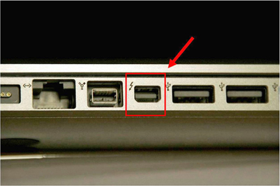
Figure 13-5 A Thunderbolt port
Mobile High-Definition Link
Mobile High-Definition Link (MHL) is a standard developed by a group of manufacturers making up the MHL Consortium. Their goal was to allow consumers to connect mobile devices and PCs to displays, monitors, and even projectors. Like other groups that have developed multifunctional, single-cable interfaces, the makers of MHL say their standard carries audio, video, data, and power charging.
The latest version, superMHL, came out in 2015 and is more like a next-generation display interface than a smartphone-connectivity solution. For one thing, superMHL features a 32-pin, full-size, symmetrical connector. It is also capable of a maximum data rate of 36 Gbps, giving it enough throughput for 7680 × 4320/120 video at 4:2:0 color sampling. See Table 13-2 for a comparison.

Table 13-2 Versions of Mobile High-Definition Link
Both MHL 3 and superMHL support the latest HDCP 2.2 version of digital rights management and can send video to multiple displays using one cable. Another noteworthy fact about superMHL is that it uses Display Stream Compression (DSC), a standard developed by VESA that employs “visually lossless image compression” to improve throughout and save power. While clients may not have an immediate need for 8K resolution, superMHL’s support for HDR, high frame rates, and a wide color gamut defined by ITU Recommendation BT.2020 (also supported by HDMI 2.0 and other technologies) may make it an attractive signal format for some AV designs.
Introduction to EDID
As an AV professional, the AV systems you’re designing are probably expensive, sleek, and modern. But what do you do when a user wants to connect an outdated digital device to your beautiful system? Managing Extended Display Identification Data will help.

Watch a video about EDID at www.infocomm.org/EDIDVideo. Appendix C provides links to all the helpful videos.
EDID is extremely important in today’s AV world. It was originally developed for use with computer-video devices but has since made its way into the commercial AV industry.
Displays and sources need to negotiate their highest common resolutions so they can display the best image quality. EDID is a way for sources and sinks (video destinations) to communicate this information among each other, eliminating the need for people to configure a system manually. In short, EDID is how a sink describes its capabilities to a source, and vice versa.
EDID is a standard data structure defined by the Video Electronics Standard Association. In a professional AV system, an EDID handshake can be between a source and the next device in line, whether it’s a display, videowall, switcher, distribution amplifier, matrix, or scaler. Without a successful handshake between source and display devices, the entire video solution could be unreliable. Therefore, creating an EDID strategy can be vital to your success as an AV designer.
During the handshake process, EDID-compliant devices swap 128-byte packets of EDID information from a table. Each of these data packets carries the following information:
• Product information, including the display manufacturer and product, serial number, and production date.
• EDID version number used for the data structure.
• Display parameters, such as whether a display accepts analog or digital inputs, its maximum horizontal and vertical size, power management capabilities, and more.
• Color characteristics, including the RGB color space conversion technique to be used.
• Timing information for audio and video sync, resolution, and more.
• Extensions, for describing extra capabilities. The most prevalent extension—CEA-861—defines the advanced capabilities of consumer devices incorporating HDMI.
Let’s say the user connects a laptop to a display. The graphics card will immediately start looking for an EDID table. The EDID table contains all the possible resolutions, frame rates, and so on, that a device can support. If a device uses DVI EDID, it consists of 128 bytes. If it extends the EDID for HDMI connections, it may transmit as many as 256 bytes. Figure 13-6 shows EDID information for a specific monitor.

Figure 13-6 A monitor’s EDID information
In a nutshell, the EDID handshake process goes like this (see Figure 13-7):

Figure 13-7 How an EDID handshake goes, if electronics could talk
1. On startup, an EDID-enabled device will use hot-plug detection (HPD) to see whether another device is on. A source device will send a 5V signal to sink devices. This signal will discover if the sink is powered up.
2. The sink sends back a signal, alerting the source that it received the original signal.
3. The source sends a command to the sink for its EDID information.
4. The EDID information is transmitted from sink to source over the display data channel (DDC).
5. The source responds to the sink with its own EDID.
6. The source sends EDID in the sink’s preferred resolution, refresh rate, and color space. The source’s selection can be manually overridden.
7. If the sink’s EDID contains extension blocks, the source will then request the blocks from the sink. Extension blocks can be compatible timings relevant to digital television, as well as supported audio formats, speaker allocation, and, if present, lip-sync delay.
Creating an EDID Strategy
Let’s say you’re installing a new video system for a university. Your customer has asked for a system and described it kind of like this:
“Our professors each have their own laptops, and they like to use PowerPoint slides or online videos in their lectures. We often have three or four different professors in each room per day. Because the professors do not have a lot of preparation time before class, we need a system where they can plug in their laptops and the information shows up on the screen immediately. We just want it to work without a hassle.”
Having an EDID strategy means that the projector will always be able to read the information from the professor’s laptops. This makes the system easy to use, which will make your customer happy. If the same signal is sent to multiple displays, EDID will allow you to control the source signal so you get a consistent, controlled signal. The goal of an EDID strategy is to allow a display to present the signal at its native resolution without scaling. It also allows an installer to set up and configure a system based on the designer’s goals.
If the system has displays of different resolutions or aspect ratios, without a proper EDID strategy, the resolution and aspect of the output will be unreliable and may vary when switching between sources.
All display devices in a video system need to have the same aspect ratio. This will prevent many EDID problems. Computers and other devices tend to have either a 16:9 or 16:10 aspect ratio, so your projectors and other display devices should reflect this. Installed display devices don’t change as rapidly as personal computers and tablets do, so the unfortunate reality is that your display devices may become outdated quickly. If you have an EDID strategy, though, then the system should still work for a long time.
One way to future-proof a system is to use the most common resolution between devices as a benchmark. That way you can ensure all displays will look the same.
Even if your source and sink have an EDID strategy, sometimes non-EDID equipment such as switchers, expanders, and cables interrupt the EDID path and cause problems. Here are some strategies to make sure the system you’re installing is EDID compliant.
An EDID emulator acts as a sink. It can be set to a specific aspect ratio and native resolution so that the source outputs a consistent aspect ratio and resolution. So, for example, a laptop will read the EDID information in the emulator instead of the EDID information from one of the multiple displays attached to the switcher. The laptop will output the fixed resolution set in the emulator.
You can use an EDID emulator to make sure your system is EDID compliant. Sometimes, switchers will already have these built into them. Place the emulator as close to the source as possible or in the switcher. This will give you the most accurate information about your system.
EDID Truth Tables
Whether planning or executing a design, you will benefit from containing your EDID information in one place. Creating a “truth table” will help you organize all of your EDID information. Currently there is no standard for documenting EDID information, so here is one example of an EDID truth table to help you organize and interpret this information on the job.
An EDID truth table should contain the following information for the inputs on a switcher:
• Input number on the switcher
• Type of connected source device
• Color space support, such as RGB or component
• Audio format
• Additional notes about the source or its settings
It also should contain the following information for the outputs on a switcher:
• Output number on the switcher
• Type of connected sink device
• Device’s native or support resolution
• Color space support, such as RGB or component
• Audio format
• Any additional notes about the sink device or its settings
Figure 13-8 shows how an EDID truth table might look. Note how the inputs and outputs are grouped together on this sample table.

Figure 13-8 An EDID truth table
Resolving EDID Issues
There a few ways to help determine whether an EDID connection is being interrupted or halted and repair the relationship. It doesn’t hurt to have an EDID field toolkit for client visits if a video system is acting up and EDID might be the culprit. Such a toolkit for troubleshooting and resolving EDID issues might include software (many are free) for determining the EDID contents of devices; a video test generator to output test patterns and show native resolutions; EDID managers or emulators; HDMI or DVI line testers for quick checks of TMDS, DDC, hot-plug detection, and power in the cable; and a network-cable tester for cases of transporting signals over twisted pair.
The following are some of the common visible symptoms that there may be an EDID issue with a video system:
• There’s no image on the screen (which, clearly, could indicate other issues).
• The image does not fill the screen.
• The image is fuzzy.
• The image is stretched.
• In multidisplay systems, the image quality is great on some displays but not all.
Sometimes you can look over the installation to figure out what the problem is. It could be that the source is connected to the sink over a long cable run, particularly for HDMI or DVI connections. Or maybe the source is connected to the sink over a long distance using a twisted-pair extender. Or there may be unreliable source switching. Whatever the case, if the client is blaming your design for what may be an EDID problem, try the following:
• Test the cable integrity using a signal generator.
• Confirm that the connectors (or cables) are what you specified, not low-quality, low-cost alternatives.
• Shorten cable runs to maintain integrity over a distance with solid connections and keep cable lengths within manufacturer guidelines.
• Check for possible electromagnetic interference (EMI)/radio frequency interference (RFI) and ground loops in the system; consider using shielded twisted pair if necessary.
• Use an EDID management software tool to ensure you’re using the preferred resolution.
• Avoid internal switchers; use a switcher or switcher/scaler with built-in EDID.
• Determine the native resolutions of all displays in the system and select the highest common resolution among them.
Digital Rights Management
Your customers may want to share or distribute content that they did not create, such as clips from a media library, a Blu-ray Disc video, or music from a satellite service. Unlicensed distribution of these materials can violate copyright laws.
Both you and your customers must be aware of potential licensing issues related to the content they want to use. You may need to negotiate a bulk license with a content service provider such as a cable or satellite television provider or a satellite music service. If you fail to obtain the proper licenses to stream content, you are not just risking the legal repercussions of copyright infringement. You are risking the system’s ability to function at all.
Publishers and copyright owners use digital rights management (DRM) technologies to control access to and usage of digital data or hardware. DRM protocols within devices determine whether content can be allowed to enter a piece of equipment. Copy protection such as the Content Scrambling System (CSS) used in DVD players is a subset of DRM.
High-Bandwidth Digital Content Protection
When you turn on a Blu-ray Disc player, for example, it takes a moment for the device to start. This is because the AV system is verifying that everything in the system is HDCP compliant.
High-Bandwidth Digital Content Protection (HDCP) is a form of encryption developed by Intel to control digital audio and video content. If the content source requires HDCP, then all devices that want to receive that content must support HDCP.
HDCP is merely a way of authorizing playback. It can authorize the transmission of encrypted or nonencrypted content. Note that while HDCP is a way to protect content from being copied, it is not a DRM technology. Think of the process as a series of handshakes. The Blu-ray Disc player communicates to the disc asking for license information. The disc then responds that it is HDCP compliant. The two shake hands. Then the Blu-ray Disc player runs the same handshake with the display.
The past few years have seen several revisions to HDCP in part to meet demand for more session keys worldwide. Versions 1.0 to 1.4 supported DVI, HDMI, and DisplayPort. Version 2.0 added support for Unified Display Interface, TCP/IP, USB, and wireless transmission of compressed and uncompressed HD content. It is interoperable with earlier versions.
The current version of HDCP, version 2.2, added support for Intel’s Wireless Display technology, Miracast, HDBaseT, MHL, and more. It entails a more advanced encryption handshake than prior versions. But there are a few other key considerations when dealing with HDCP 2.2 in an AV design.
For starters, HDCP 2.2 is not backward compatible. It is implemented at a hardware level, so there are no firmware solutions for upgrading devices. When it comes to 4K, native 4K sources will include HDCP 2.2; therefore, all devices between the source and sink must also be HDCP 2.2–compliant, including receivers, switches, extenders, and so on.
How HDCP Works
HDCP’s authentication process determines whether both devices have been licensed to send, receive, or pass HDCP content. No content will be shared until this entire process is completed. If there is a failure at any point in the process, the whole process has to start over. The process goes like this:
1. Both source and sink calculate a shared, secret session key used for encrypting and decrypting data.
2. The source sends its key to the sink, along with a pseudorandom value generated by its cipher (or encryption algorithm).
3. The sink sends its key to the source, along with a single bit that indicates whether it’s a repeater device.
4. They both generate a shared secret value that’s in each device.
5. The source and sink feed the shared secret value and the pseudorandom number into their internal HDCP code cipher engine.
6. The HDCP cipher generates a secret, shared session key along with another value, which the sink sends to the source to indicate it has successfully completed its part of the authentication process.
7. The source compares the value with its own calculated value, and if the two are identical, authentication is successful.
8. The source can then start sending a stream of content, encrypted using the session key, which only the receiver can decipher.
9. If the sink is a repeater, it transmits a list of all keys connected “downstream” from it and how many levels of devices are connected to the source. This enables the source to determine whether the maximum number of allowed hops in the system has been exceeded and if the devices themselves are legitimate.
10. From then on, the sink reinitiates a handshake with source every 128 video frames or once every two seconds to verify devices are synchronized and content is accurately decrypted.
Now, even though content is streaming, the authentication process is not over. The HDCP devices must re-authenticate periodically as the content is transferred. If, during re-authentication, it is discovered that the system was hacked, the source will stop sending content.
Watch a video about HDCP at www.infocomm.org/HDCPVideo. Appendix C provides links to all the helpful videos in this guide.
Switchers and Repeaters
All the HDCP processes explained so far have assumed that your AV system has a one-to-one relationship, with a single source for a single sink. In these systems, the keys and how they’re exchanged are handled continuously between the two devices.
However, as soon as you add multiple sources and displays—and maybe a switcher to manage them—HDCP key management becomes more complicated. Some switchers maintain ongoing key exchange and encryption sessions, so the communication will not need to be restarted. These switchers can act as a source or sink to pass the protected and encrypted HDCP data to its destination. You can determine whether a switcher can manage HDCP keys by reading its specifications.
TIP HDCP 2.2 is incompatible with legacy components, such as switchers. Under this new content protection scheme, clients wanting to utilize 4K video will need HDCP 2.2–compliant devices.
Incorporating HDCP repeaters into the AV system’s design can help you manage HDCP authentication with multiple devices. When using a repeater, the HDCP authentication process occurs after the locality check and device authentication have taken place between all the devices in the system. The session key exchange has not begun yet.
1. The repeater compiles a list of IDs from all the downstream devices.
2. The repeater sends the list of IDs and number of devices to the source and sets a 200 ms timer.
3. The source reads the list and compares it to a list of revoked licenses in the media. Each new HDCP device or media has an updated list of revoked license numbers provided by Digital Content Protection LLC. If any of the downstream devices are on the revoked list, the authentication process fails.
4. The source then counts how many devices are downstream. If the number of devices is less than the maximum, the authentication process moves forward.
NOTE The way devices such as repeaters are designed and manufactured today, each input is considered a new sink, and each output is a new source. You must have enough session keys for every device in the AV system or risk.
HDCP Troubleshooting
Once your system has been designed and installed, you need a method for verifying that the HDCP keys are being managed correctly. You know that your keys are being managed correctly if the image appears on the sink and is stable over a period of time. If the HDCP keys are not managed correctly, an image constraint token (ICT) or a digital-only token (DOT) will be displayed on your sink.
An ICT is a digital flag built into some digital video sources. It prevents unauthorized copies of content from appearing on a sink device. This encryption scheme ensures that high-definition video can be viewed only on HDCP-enabled sinks. A DOT is a digital flag that is embedded into digital sources, such as Blu-ray Discs. Its purpose is to limit the availability or quality of HD content on the component output of a media player.
There are devices on the market to help you troubleshoot HDCP problems. Some have feature sets that may include the following:
• Hot-plug/5V presence detection
• DisplayID/EDID verification
• HDCP status indication
• Indication of the number of keys accepted by the source (in other words, the maximum number of devices supported)
• Cable verification
Managing HDCP can be a challenge, but remember that if your client wants to bypass digital rights management, they shouldn’t. Most countries have adopted some form of copyright law that criminalizes attempts to circumvent control access to copyrighted works. Be sure to make your clients aware of these laws when discussing their needs on a project.
Chapter Review
Digital video is often oversimplified—either the video appears at its destination or it doesn’t. Having completed this chapter, you know some of the intervening issues that come with designing digital video systems and how to manage them.
Here are some of the questions you’ll work through with clients when determining their digital video needs: “What transport solutions can I employ based on the needs and budget of the client? Will I face distance limitations? Bandwidth limitations? If the client wants 4K, what implementation of 4K will satisfy their needs? Are the system’s devices HDCP 2.2 compliant? Do they need to be? What should our EDID strategy be in the case of multiple displays and display formats and resolutions?” With this information and more, your digital video design will deliver what the client expects—reliably.
Review Questions
The following questions are based on the content covered in this chapter and are intended to help reinforce the knowledge you have assimilated. These questions are not extracted from the CTS-D exam nor are they necessarily CTS-D practice exam questions. For an official CTS-D practice exam, download the Total Tester as described in Appendix D.
1. Ultra high-definition video (UHD) describes video formats with a minimum pixel resolution of:
A. 1920 × 1080
B. 3840 × 2160
C. 4096 × 2160
D. 7680 × 4160
2. To transmit 4K video at 60 fps using HDMI 1.4, color information should be sampled at a rate of:
A. 4:4:4
B. 4:2:2
C. 4:2:0
D. 4:0:0
3. A video system design to transmit 4K at 60 fps, with 4:4:4 chroma sampling and 10 bits per color, requires about __________ of throughput.
A. 10 Gbps
B. 16 Gbps
C. 22 Gbps
D. 32 Gbps
4. Both __________ use transition-minimized differential signaling to transmit high-speed serial data.
A. DVI and HDMI
B. HDMI and DisplayPort
C. DVI and DisplayPort
D. superMHL and DisplayPort
5. In a video system with multiple displays, problems with image quality in some, but not all, displays could indicate a problem with what?
A. The video formats used
B. The lengths of the video cables
C. Incompatible High-Bandwidth Digital Content Protection keys
D. Extended Display Identification Data
6. An EDID truth table should contain which of the following to describe the inputs of a switcher? (Choose all that apply.)
A. The version of EDID used
B. Input numbers
C. Preferred resolution
D. Color space support, such as RGB or a component
7. Clients who want to deploy 4K video over an integrated video system will likely need __________ devices to make it work properly.
A. HDCP 2.2–compliant
B. DisplayPort 1.2–compatible
C. 8 Gbps–capable
D. 4:2:0-sampled
8. An image constraint token onscreen indicates a problem with __________.
A. HDMI
B. UHDTV
C. EDID
D. HDCP
Answers
1. B. Ultra high-definition video (UHD) describes video formats with a minimum pixel resolution of 3840 × 2160.
2. C. To transmit 4K video at 60 fps using HDMI 1.4, color information should be sampled at a rate of 4:2:0.
3. C. A video system design to transmit 4K at 60 fps, with 4:4:4 chroma sampling and 10 bits per color, requires about 22 Gbps of throughput.
4. A. DVI and HDMI use transition-minimized differential signaling to transmit high-speed serial data.
5. D. In a video system with multiple displays, problems with image quality in some, but not all, displays could indicate an Extended Display Information Data (EDID) problem.
6. B, C, D. An EDID truth table should include information about input numbers, preferred resolutions, and color spaces.
7. A. Clients who want to deploy 4K video over an integrated video system will likely need HDCP 2.2–compliant devices to make it work properly.
8. D. An image constraint token onscreen indicates a problem with HDCP.